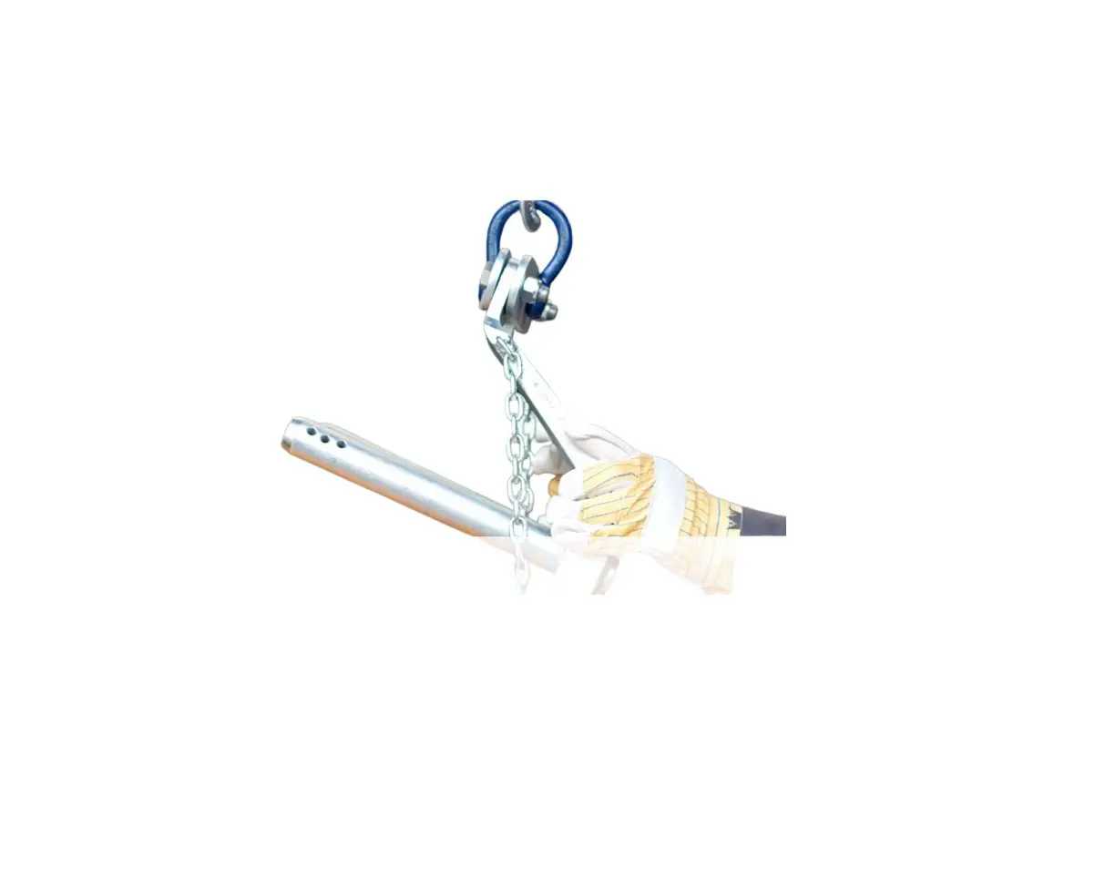
trs Flange Lifting Hook
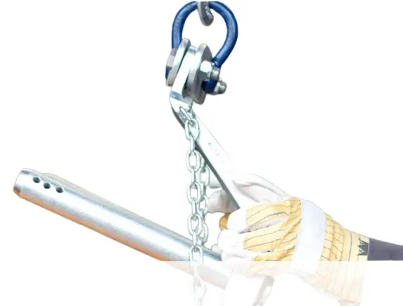
INTRODUCTION
The Flange Lifting Hook is a simple piece of lifting equipment, however operatives should be trained and experienced in lifting operations and the safe guidance of hoisted objects, preferably having LOLER qualifications.
There are a few points to be aware of prior to using the Flange Lifting Hook.
![]() The Flange Lifting Hook can only be used on horizontal heat exchangers!
The Flange Lifting Hook can only be used on horizontal heat exchangers!
The Flange Lifting Hook is available in a range of sizes. Check the selection table (below) prior to use. The correct choice of the proper size is determined by:
- the bolt diameter
- the flange thickness and
- the weight of the object to be lifted (pressure ring, flat cover, floating head, blind plate)
SELECTING THE APPROPRIATE FLANGE LIFTING HOOK
- Determine the bolt-hole diameter of the object to be hoisted. Select the best fitting diameter of the lifting pin to be used from the table. This lifting pin diameter has to be as large as possible, but smaller than the bolt-hole diameter.
- Determine the flange thickness of the object to be hoisted (“length of the bolt-hole”) and add 10mm to be able to install the attached locking pins into the lifting pins. This is the required working length of the lifting pins. It is not safe to use a shorter working length!
- The range between the minimum and maximum working length per lifting pin is 30mm. The working length is to be chosen within this range. Look up the determined working length in selection table.
- The total pin length is the maximum working length of the pin + 20mm. The total pin length is stated in the type specification as well as in the product code of the Flange Lifting Hook to be used.
- Determine the weight of the object to be hoisted. This is the minimum required lifting capacity.
 Check the weight of the object does not exceed the lifting capacity of the Flange Lifting Hook!
 - The correct Flange Lifting Hook has now been determined and the choice has been checked.
- Each Flange Lifting Hook is supplied with a valid lifting certificate. Check that:
the numbers on the Flange Lifting Hook are the same as stated on the lifting certificate
the same number is stamped on both legs and the shackle
the lifting certificate is valid and that the dates are current according to LOLER requirements A Flange Lifting Hook with an invalid or expired certificate should not be used!
In this case, arrange for the unit to be inspected by a LOLER qualified engineer before use. - If details of the certificate are correct, then the Flange Lifting Hook should be checked for visual defects:
• check that the locking pin properly fixed
• check that the bolts and nuts in the bridge properly fixed
• check that the lifting pins are not bent or twisted
• check that the welds are not cracked
• check that each leg is fitted with a chain and with the original self-latching locking pin attached
• check that the locking pins are not bent or twisted If any defects are discovered, or if in doubt the Flange Lifting Hook should not be used!
In this case, arrange for the unit to be inspected by a LOLER qualified engineer before use. - The selected Flange Lifting Hook may only be used according to the procedures, and only if it fulfils the above mentioned requirements.
DEMOUNTING INSTRUCTIONS
- Mount the Flange Lifting Hook on to the correct crane hook and make sure that the crane hook is in a vertical line above the object to be hoisted. The Flange Lifting Hook must NEVER be used in a slant pulling direction!
- Slide the lifting pins of the Flange Lifting Hook until they heal into the upper bolt-holes of the object to be hoisted. Make sure that the legs of the Flange Lifting Hook are as vertical as possible.
- Always mount the locking pins into the lifting pins as close as possible against the object to be hoisted (maximum tolerance 10mm).
- Hoist the Flange Lifting Hook slightly until the hoisted load is hanging in the crane hook only and does not rest on the bolts anymore. Remove the remaining bolts from the bolt-holes.
- Hoist the object in accordance to the crane procedures and check that the object is tilted slightly backwards while hanging in the crane hook. The load must hang freely and vertically under the crane hook. NEVER use the Flange Lifting Hook to pry components of the heat exchanger!
- Allow the crane driver to carefully lower the object until it has safely landed on timber supports.
- Have the crane carefully lowering the object backwards on the ground and guide the object during this
procedure. Make sure that the locking pins are on the top side of the object for easy removal. - Remove the crane hook from the Flange Lifting Hook.
- Remove the locking pins out of the lifting pins of the Flange Lifting Hook.
- Remove the Flange Lifting Hook from the bolt-holes of the object.
MOUNTING INSTRUCTIONS
- Mount the lifting pins of the Flange Lifting Hook from the bottom side until they heal through two of the bolt-holes of the object to be hoisted. Fix the Flange Lifting Hook with the locking pins (maximum tolerance 10mm). Make sure that the legs of the Flange Lifting Hook are mounted as parallel as possible.
- Hook the crane hook to the Flange Lifting Hook.
- Have the crane driver hoist the object gently in a vertical position and guide it during this operation.
- Have the crane driver hoist the object towards the relevant heat exchanger according to procedure.
- Guide the object to the place to be mounted and make sure that no packing face and/or gasket is damaged due to this action.
- Position the object on its mounting place and install sufficient bolts to secure the object in place.
- Allow the crane driver to slowly lower the object until the total weight is resting on the bolts.
- Remove the locking pins from the lifting pins, then remove the lifting pins of the Flange Lifting Hook from the bolt-holes.
- Remove the Flange Lifting Hook from the crane hook.
* If the required lifting capacity at the determined pin diameter and pin length is not listed in the selection table (below), then please contact the supplier. It may be possible to obtain a custom-built solution (such as two identical Flange Lifting Hooks in combination with a spreader beam.
FLANGE LIFTING HOOK
SELECTION TABLE | ||||||||||||||
Safe Working Load (SWL) | Pin Length (mm) | Pin Diameter (mm) | ||||||||||||
| Required* | Total | 19 | 22 | 25 | 28 | 30 | 32 | 35 | 38 | 45 | 50 | 55 | 60 | |
| <80 | 100 | |||||||||||||
| Capacity (SWL) | 1000kg | 1500kg | 2000kg | 3000kg | 3000kg | 3000kg | 3000kg | 3000kg | 3000kg | 3000kg | 3000kg | 3000kg | ||
Model Number | 100019100 | 150022100 | 200025100 | 300028100 | 300030100 | 300032100 | 300035100 | 300038100 | 300045100 | 300050100 | 300055100 | 300060100 | ||
| Product Code | 181210 | 181220 | 181230 | 181240 | 181250 | 181260 | 181270 | 181280 | 181290 | 181300 | 181310 | 181320 | ||
| 81 – 110 | 130 | |||||||||||||
Capacity (SWL) | 750kg | 1150kg | 1700kg | 2400kg | 2900kg | 3000kg | 3000kg | 3000kg | 3000kg | 3000kg | 3000kg | 3000kg | ||
| Model Number | 075019130 | 115022130 | 170025130 | 240028130 | 290030130 | 300032130 | 300035130 | 300038130 | 300045130 | 300050130 | 300055130 | 300060130 | ||
Product Code | 181209 | 181219 | 181229 | 181239 | 181249 | 181259 | 181269 | 181279 | 181289 | 181299 | 181309 | 181319 | ||
| 111 – 140 | 160 | |||||||||||||
Capacity (SWL) | 600kg | 900kg | 1300kg | 1850kg | 2300kg | 2800kg | 3000kg | 3000kg | 3000kg | 3000kg | 3000kg | 3000kg | ||
Model Number | 060019160 | 090022160 | 130025160 | 185028160 | 230030160 | 280032160 | 300035160 | 300038160 | 300045160 | 300050160 | 300055160 | 300060160 | ||
| Product Code | 181208 | 181218 | 181228 | 181238 | 181248 | 181258 | 181268 | 181278 | 18/1288 | 18/1298 | 18/1308 | 18/1318 | ||
| 141 – 170 | 190 | |||||||||||||
Capacity (SWL) | 500kg | 750kg | 1100kg | 1550kg | 1900kg | 2300kg | 3000kg | 3000kg | 3000kg | 3000kg | 3000kg | 3000kg | ||
| Model Number | 050019190 | 075022190 | 110025190 | 155028190 | 190030190 | 230032190 | 300035190 | 300038190 | 300045190 | 300050190 | 300055190 | 300060190 | ||
Product Code | 181207 | 181217 | 181227 | 181237 | 181247 | 181257 | 181267 | 181277 | 181287 | 181297 | 181307 | 181317 | ||
| 171 – 200 | 220 | |||||||||||||
Capacity (SWL) | 400kg | 600kg | 900kg | 1300kg | 1600kg | 1950kg | 2500kg | 3000kg | 3000kg | 3000kg | 3000kg | 3000kg | ||
| Model Number | 040019220 | 060022220 | 090025220 | 130028220 | 160030220 | 195032220 | 250035220 | 300038220 | 300045220 | 300050220 | 300055220 | 300060220 | ||
Product Code | 181206 | 181216 | 181226 | 181236 | 181246 | 181256 | 181266 | 181276 | 181286 | 181296 | 181306 | 181316 | ||
| 201 – 230 | 250 | |||||||||||||
Capacity (SWL) | 350kg | 550kg | 800kg | 1150kg | 1400kg | 1700kg | 2200kg | 2800kg | 3000kg | 3000kg | 3000kg | 3000kg | ||
| Model Number | 035019250 | 055022250 | 080025250 | 115028250 | 140030250 | 170032250 | 220035250 | 280038250 | 300045250 | 300050250 | 300055250 | 300060250 | ||
Product Code | 181205 | 181215 | 181225 | 181235 | 181245 | 181255 | 181265 | 181275 | 181285 | 181295 | 181305 | 181315 | ||
| 231 – 260 | 280 | |||||||||||||
Capacity (SWL) | 300kg | 500kg | 700kg | 1000kg | 1250kg | 1500kg | 1950kg | 2500kg | 3000kg | 3000kg | 3000kg | 3000kg | ||
| Model Number | 030019280 | 050022280 | 070025280 | 100028280 | 125030280 | 150032280 | 195035280 | 250038280 | 300045280 | 300050280 | 300055280 | 300060280 | ||
Product Code | 181204 | 181214 | 181224 | 181234 | 181244 | 181254 | 181264 | 181274 | 181284 | 181294 | 181304 | 181314 | ||
| 261 – 290 | 310 | |||||||||||||
Capacity (SWL) | 250kg | 450kg | 650kg | 900kg | 1100kg | 1350kg | 1750kg | 2200kg | 3000kg | 3000kg | 3000kg | 3000kg | ||
Model Number | 025019310 | 045022310 | 065025310 | 090028310 | 110030310 | 135032310 | 175035310 | 220038310 | 300045310 | 300050310 | 300055310 | 300060310 | ||
| Product Code | 181203 | 181213 | 181223 | 181233 | 181243 | 181253 | 181263 | 181273 | 181283 | 181293 | 181303 | 181313 | ||
*Required pin length = length of bolt-hole / thickness of flange +10mm
Some heat exchangers do have rather small bolt-hole diameters and therefore the S.W.L. of the corresponding Flange Lifting Hook might be insufficient. In order to double the S.W.L. one should order two equal size Flange Lifting Hooks plus relevant spreader beam (ordered separately).
Selection example:
Weight of channel cover = 1018kg
Thickness of flange = 113mm + 10mm = required pin length of 123mm
Bolt-hole diameter = 21mm
Suggested Flange Lifting Hook (according to selection table)
S.W.L. type 060019160 (181208) = 600kg = 1200kg
Required minimum S.W.L. = 1018kg
S.W.L. of two of each Flange Lifting Hook, Model 060019160 (181208) = 2 x 600kg = 1200kg
- total pin length = 160mm
- pin diameter = 19mm
- type 060019160 (181208)
- 600kg
- double Flange Lifting Hook necessary!
- suitable!
CUSTOMERS SUPPORT
Available from:
Total Rental Solutions Ltd
Unit H3
Morton Park Way
Darlington
DL1 4PH
Tel: 01325 609040
Email: [email protected]
www.trs-hire.com
Total Rental Solutions Ltd
Unit H3
Morton Park Way
Darlington
DL1 4PH
Tel: 01325 609040
[email protected]
www.trs-hire.com