D-Link DSS-200G-10MP Base-T Ports PoE Switch
Package Contents
Open the shipping carton of the switch and carefully unpack its contents. Please consult the packing list to make sure all items are present and undamaged. If any item is missing or damaged, please contact your local reseller for replacement.
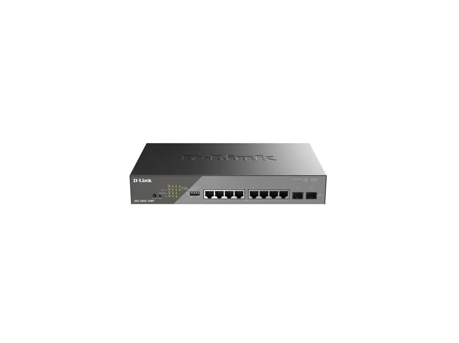
- One DSS-200G-10MP switch
- One AC power cord
- One Quick Installation Guide
Note: the model you have purchased may appear slightly different from those shown in the illustrations.
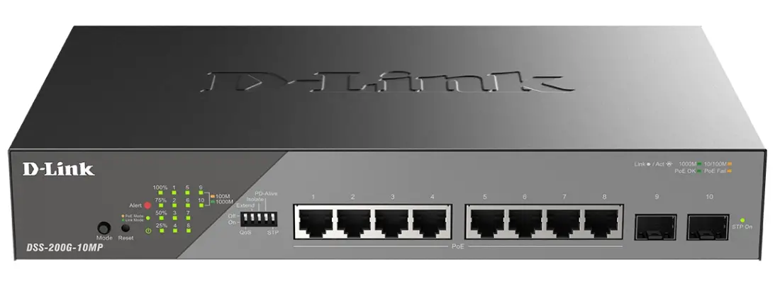
Device Interfaces
| Port | Description |
| 10/100/1000Base-T PoE ports | 8 10/100/1000Base-T PoE ports (10/100/1000 Mbps connection speed). |
| 1000Base-X SFP ports | 2 1000Base-X SFP ports (100/1000 Mbps connection speed). |
| RJ-45 Alarm port | RJ-45 Alarm port for connecting external alarm devices. |
LEDs
| LED | Status | Description |
| Power | Solid green | The switch is powered on. |
| Light off | The switch is powered off. | |
| Alert | Solid red | The alarm is triggered. Switch will send out traps and logs when error event. |
| PoE Mode/Link Mode | Solid amber | LEDs for ports 1-8 are in PoE Mode (PoE OK/PoE Fail). |
| Solid green | LEDs for ports 1-8 are in Link Mode (Link/Activity/Speed). | |
| Link/Activity/Speed (per port 1-8) | Solid green | There is a secure 1000 Mbps connection at the port. |
| Blinking green | There is reception or transmission occuring at the port. | |
| Solid amber | There is a secure 10/100 Mbps connection at the port. | |
| Blinking amber | There is reception or transmission occuring at the port. | |
| Light off | No link. | |
| Link/Activity/Speed (per port 9-10) | Solid green | There is a secure 1000 Mbps connection at the port. |
| Blinking green | There is reception or transmission occuring at the port. | |
| Solid amber | There is a secure 100 Mbps connection at the port. | |
| Blinking amber | There is reception or transmission occuring at the port. | |
| Light off | No link. | |
| PoE OK/PoE Fail (per PoE port) | Solid green | PD device insert and power feeding. |
| Solid amber | PD device insert but failure occurs. | |
| Light off | No PD device insert. | |
| PoE Power Budget | 100% LED: Solid red | PoE power has reached 100% |
| 75% LED: Solid amber | PoE power ≤ 75%. | |
| 50% LED: Solid green | PoE power ≤ 50%. | |
| 25% LED: Solid green | PoE power ≤ 25%. |
Installation Guidelines
This section will discuss the hardware installation guidelines that the user must follow in order to properly and safely install this switch into the appropriate environment.
- Visually inspect the power cord to see that it is secured fully to the AC power connector.
- Make sure that there is proper heat dissipation and adequate ventilation around the switch.
- Do not place heavy objects on the switch.
Desktop or Shelf Installation
When installing the switch on a desktop or shelf, the rubber feet must be attached on the bottom at each corner of the device’s base. Allow enough ventilation space between the device and the objects around it.
Figure 1 — Attaching rubber feet to the switch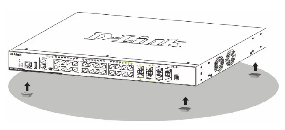
Rack Installation
The switch can be mounted in an EIA standard size 19-inch rack, which can be placed in a wiring closet with other equipment. To install, attach the mounting brackets to the switch’s side panels (one on each side) and secure them with the screws.
Figure 2 — Attaching rack-mount brackets to the switch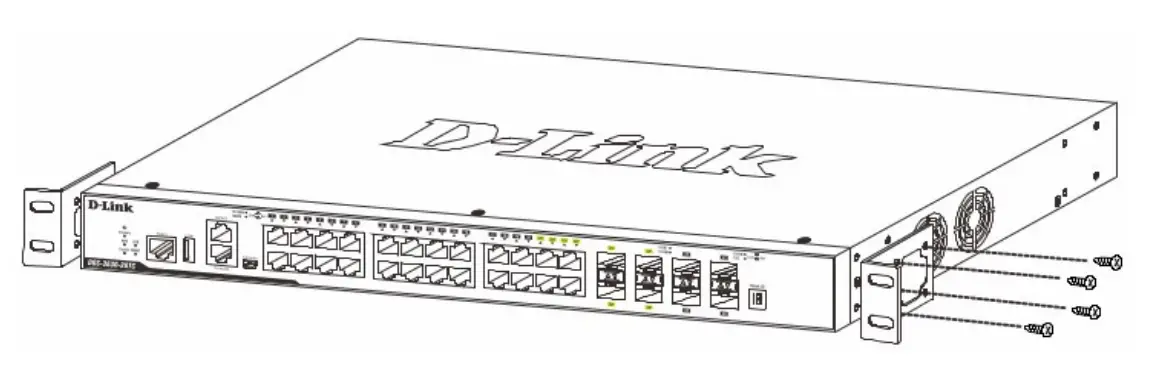
Then, use the screws provided with the equipment rack to mount the switch in the rack.
Figure 3 — Installing the switch in a rack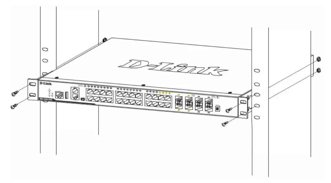
Installing Transceivers into the Transceiver Ports
The DSS-200G-10MP switch is equipped with the ports for connecting the SFP transceivers.
Figure 4 — Inserting transceivers into the transceiver ports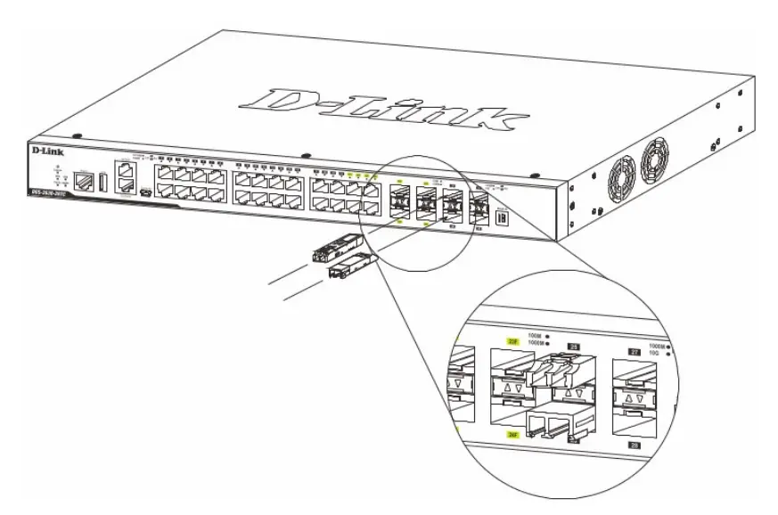
Grounding the Switch
This section describes how to connect the switch to the ground. You must complete this procedure before powering on the switch.
Required tools and equipment:
- Ground screws: One M4 x 6 mm (metric) pan-head screw.
- Grounding cable (not included in the accessory kit): The grounding cable should be sized according to local and national installation requirements. Depending on the power supply and system, a 12 to 6 AWG copper conductor is required for installation. Commercially available 6 AWG wire is recommended. The length of the cable depends on the proximity of the Switch to proper grounding facilities.
- A screwdriver (not included in the accessory kit).
You can connect the switch to a protective ground by following the steps below:
- Verify if the switch power is off.
- Attach the terminal lug ring of the grounding cable to the ground screw opening of the switch with the grounding screw.
- Attach the terminal lug ring at the other end of the grounding cable to an appropriate grounding stud or bolt on the rack where the switch is installed.
- Verify if the connections at the ground connector on the switch and the rack are securely attached.
Plugging in the AC Power Cord
Plug one end of the AC power cord into the power socket of the switch and the other end into the electrical outlet (preferably one that is grounded and surge protected).
Power Failure
In the event of a power failure, just as a precaution, unplug the power cord from the switch. After the power returns, plug the power cord back into the power socket of the switch.
Technical support
Software updates and documentation available on the website D Link. D-Link provides free customer support for warranty period. Customers can contact the technical support team D-Link by phone or via the Internet. D-Link technical support works around the clock every day except public holidays. The call is free throughout Russia.
D-Link technical support:
8-800-700-5465
Online technical support:
http://www.dlink.ru
e-mail: [email protected]
Manufacturer:
D-Link Corporation, 11494, Taiwan, Taipei, Neihu District, Xinghu 3 Road, No. 289
Authorized representative, importer:
D-Link Trade LLC
390043, Ryazan, Shabulina Ave., 16
Tel.: +7 (4912) 575-305
Office address in Russia:
Moscow, Grafsky lane, 14
Tel.: +7 (495) 744-00-99
e-mail: [email protected]