ProTech EPA07 Engine Exhaust
INSTALLATION INSTRUCTION
2-Channel Accelerator Pedal Signal 2 Missing
| SPN 2623/FMI 8 | |
| Description | Channel 2 Sensor Signal Failed (High Or Low) |
| Monitored Parameter | GAS2 |
| Typical Enabling Conditions | Always ON |
| Monitor Sequence | None |
| Execution Frequency | Continuous When Enabling Conditions Met |
| Typical Duration | Two Seconds |
| Dash Lamps | CEL |
| Engine Reaction | None |
| Verification | Key Cycle – Ignition ON |
WARNING
ENGINE EXHAUST
To avoid injury from inhaling engine exhaust, always operate the engine in a well-ventilated area. Engine exhaust is toxic.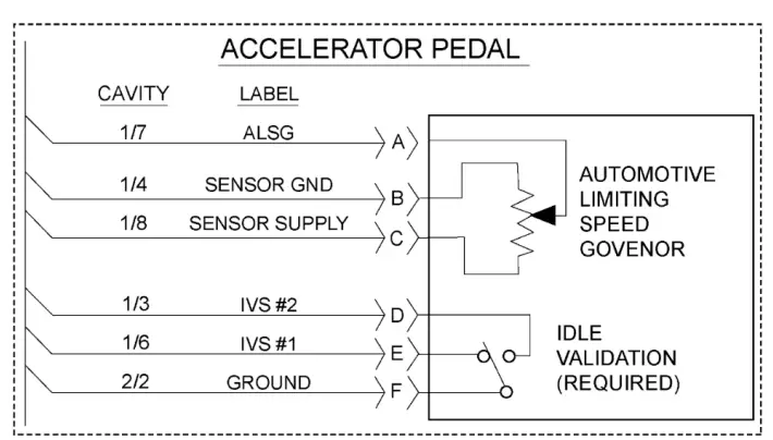
- Fig 0.1, Analog Pedal Type
EPA07 10 GHG14 DDEC VI 10 Electronics and Troubleshooting Manual (DDC-SVC-MAN-0084)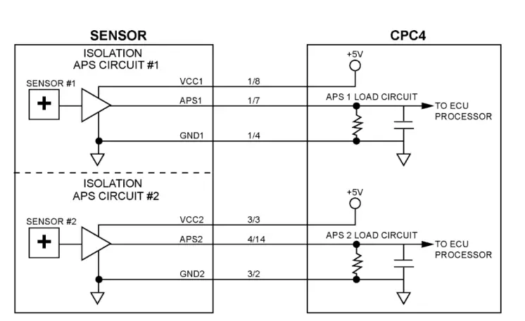
- Fig 0.2, Dual-Channel Analog Pedal
| Williams Dual-Channel Pedal Connector and Pinout | ||||
| Function | CPC Pinout | Connector Pinout | Comments | Connector Body |
| APS1 | 1/7 | A | Sensor 1 | |
| GND1 | 1/4 | B | APS 1 GND | |
| VCC1 (+5V) | 1/8 | C | APS1 Power Supply | |
| VCC2 (+5V) | 3/3 | D | APS2 Power Supply | |
| GND2 | 3/2 | E | APS2 GND | |
| APS2 | 4/14 | F | Sensor 2 | |
Check as follows:
- Disconnect the Accelerator Pedal (AP).
- Inspect the AP and harness side connectors for signs of damaged, bent, spread, corroded or unseated (pushed out) pins and signs of moisture in the connector or wire damage near the connector. Is any damage found? 2. a Yes; repair as necessary. Verify repair. 2.b No; Go to step 3.
- Turn the ignition ON (key ON, engine OFF).
- Measure the voltage between pin B of the AP harness connector and ground. Is voltage present?
a Yes; repair the short to power between pin B of the AP harness connector and pin 4 of the CPC connector #1. Verify repair. 4.b No; Go to step 5. - Is the vehicle equipped with a Williams Dual-Channel Analog Pedal? 5.a Yes; Go to step 6. 5.b No; Go to step 15.
- Disconnect the CPC connector #3.
- Measure the resistance between pin D of the AP harness connector and pin 3 of the CPC connector #3. Is the resistance less than five ohms? a Yes; reconnect the CPC connector #3. Go to step 8. 7.b No; repair the open circuit between pin D of the AP harness connector and pin 3 of the CPC connector7.b No; repair the open circuit between pin D of the AP harness connector and pin 3 of the CPC connector #3. Verify repair.
- Measure the voltage between pin D of the AP harness connector and ground. Is the voltage between 4.5 and 5.5 volts? a Yes; repair the open circuit between pin E of the AP harness connector and pin 2 of the CPC connector #3 . Verify repair. 8.b No; Go to step 9.
- Measure the voltage between pin D of the AP harness connector and ground. Is voltage greater than 5.5 volts? a Yes; repair the short to battery power between pin D of the AP harness connector and pin 3 of the CPC connector #3. Verify repair. 9.b No; Go to step 10.
- Measure the voltage between pin E of the AP harness connector and ground. Is voltage present? a Yes; repair the short to power between pin E of the AP harness connector and pin 2 of the CPC connector #3. Verify repair. 10.b No; Go to step 11.
- Disconnect the CPC connector #4.
- Measure the resistance between pin F of the AP harness connector and pin 14 of the CPC connector #4. Is the resistance less than five ohms? a Yes; reconnect the CPC connector #4. Go to step 13. 12.b No; repair the open circuit between pin F of the AP harness connector and pin 14 of the CPC connector #4. Verify repair.
- Measure the resistance between pin F of the AP harness connector and ground. Is the resistance greater than 10K ohms? a Yes; Go to step 14. b No; repair the short to ground circuit between pin F of the AP harness connector and pin 14 of the CPC connector #4. Verify repair.
- Measure the voltage between pin F of the AP harness connector and ground. Is voltage present? a Yes; repair the short to power between pin F of the AP harness connector and pin 14 of the CPC connector #4. Verify repair. b No; replace the AP. Refer to Original Equipment Manufacturer (OEM) literature.
- Disconnect the CPC connector #2.
- Measure the resistance between pin F of the AP harness connector and pin 2 of the CPC connector #2. Is the resistance less than five ohms? a Yes; reconnect the CPC connector #2. Go to step 17.
- b No; repair the open circuit between pin F and pin 2 of the CPC #2 connector. Verify repair.
- Measure the voltage between pin F of the AP harness connector and ground. Is voltage present?
a Yes; repair the short to power between pin F of the AP harness connector and pin 2 of the CPC connector #2. Verify repair. b No; replace the AP. Refer to Original Equipment Manufacturer (OEM) literature. Verify repair.


