DINAN D660-0088-BLK Exhaust System Instruction Manual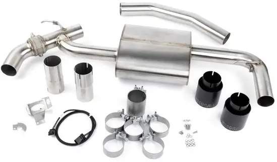
Thank you for being selective enough to choose a Dinan Performance Exhaust System. The Dinan Engineering Team has spent many hours developing this product to assure that you will receive increased performance, durability and an aesthetic design that you as a customer will be able to enjoy for many years. Ease of installation and maintenance is important to us and has been highly considered throughout the design process.
Prior to performing the installation, familiarize yourself with these instructions as it should help you with the process. If you feel that you do not have the required skills or tools, please arrange for a qualified repair facility to perform the installation.
If you have any difficulties during the installation, or if these instructions are not clear to you, please call Dinan’s Technical Support Staff at (800) 341-5480.
Again, thank you for choosing Dinan. Enjoy.
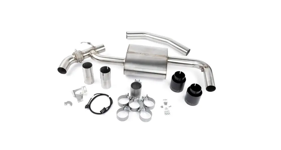
Parts List
Quantity | Part# | Description |
| 1 | D663-0360 | Muffler Assembly; F60 |
| 1 | D662-0670 | Inlet Tube; X1/X2 FWD |
| 2 | D662-0652 | Outlet Extension |
| 1 | D663-0367 | Hardware Kit |
| 1 | D662-0433 | Exhaust Valve Mount |
| 1 | D662-0665 | D76 Limiter |
| 3 | D671-0189 | M6 Locknut |
| 3 | D671-0193 | M6x20 Socket Head Bolts |
| 2 | D671-0377 | M6x12 Socket Head Bolts |
| 1 | D671-0378 | M6x16 Socket Head Bolts |
| 9 | M6 Flat | Washer |
| 3 | M6 Wave | Washer |
| 4 | D662-9228 | Single Bolt Clamp, 69.9mm |
| 1 | D662-9241 | Double Bolt Clamp, 69.9mm |
| 1 | D662-9237 | 3.00″ Clamp |
| 6 | D502121 | 5″ Tie Straps |
| 1 | D662-0431 | Extension Harness |
| 2 | D663-0600 | 4″ Exhaust Tip, Polished |
| OR | ||
| 2 | D663-0601 | 4” Exhaust Tip, BLK |
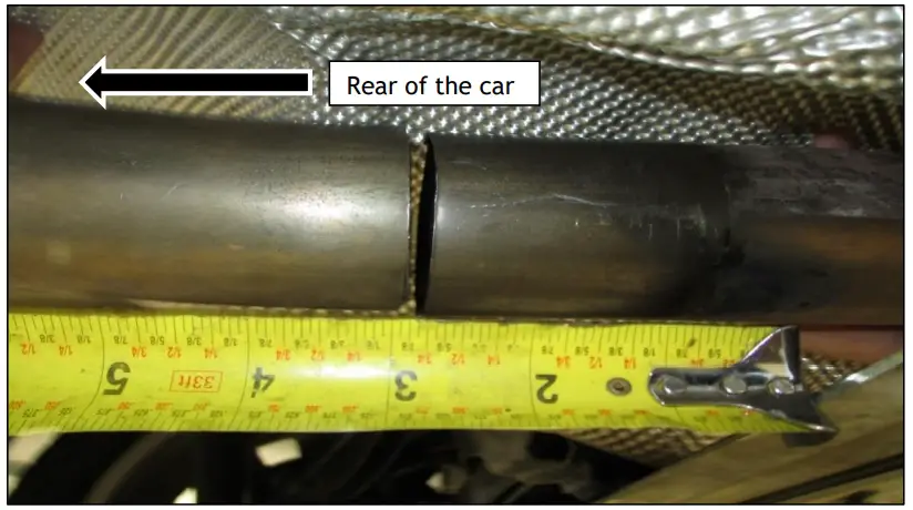
Removal: Stock System
- Cut the exhaust pipe 2 ¾”, measured from the rear edge of the brace.
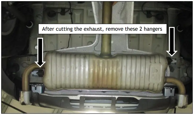
- Ensure the exhaust system is supported and unbolt the hanger assembly from the car.
- Remove the cut stock system from the car.
- Remove rubber grommets from stock system. The stock hangers will be re-used.

Figure 1: Cut Point
Figure 2: Hanger Location
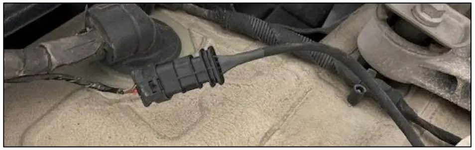
Installation of Exhaust Valve Wiring
- Unplug the stock exhaust valve motor.
- Attach the Dinan Extension Harness to the stock exhaust valve plug.

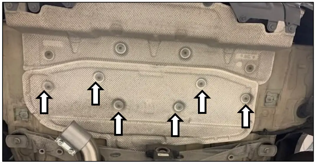
Figure 3: Attaching the Dinan Harness - Loosen the heat shield bolts and run the wiring underneath the heat shield and across to the other side of the car.

Figure 4: Removing Exhaust Heat Shield - Once the wiring is run across, secure the heat shield back in place with the wiring behind it. Be sure not to pinch the wire with any of the heat shield screws.
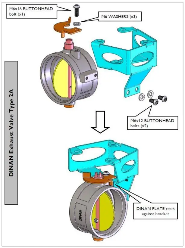
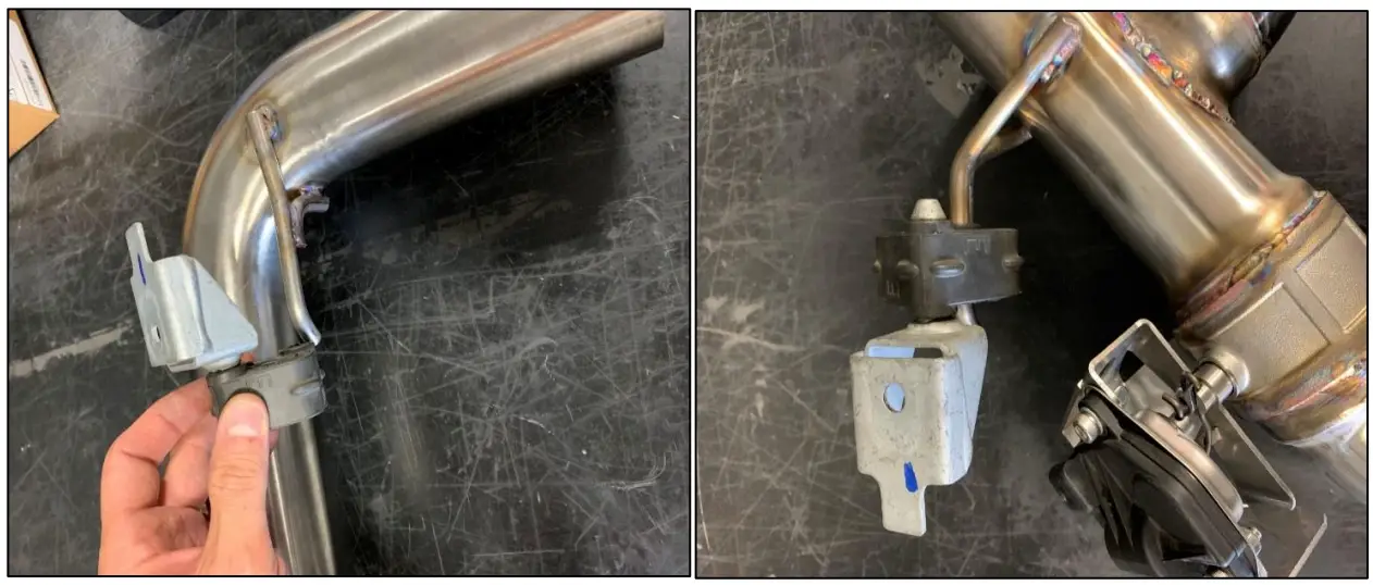
Assembly: Valve Brackets/Motor
- Assemble the exhaust valve mount (blue) and D76 limiter (orange) to the valve as shown in Figure 5.
- Ensure all bolts are tight.

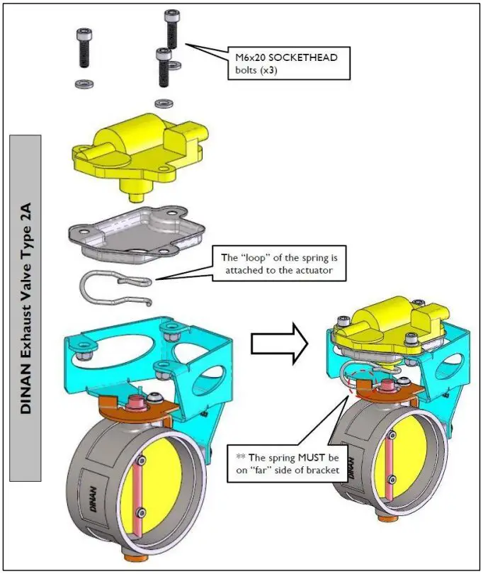
Figure 5: Assembly- Valve Bracket - Using supplied hardware, install motor and spring as shown in Figure 6.

Figure 6: Assembly: Valve Motor
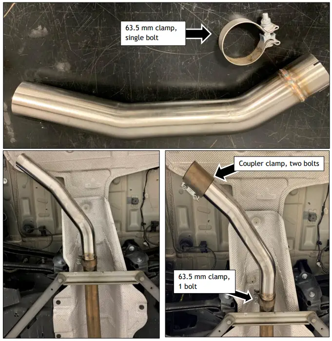
Installation of Dinan System
- Slide the 63.5mm clamp onto the inlet tube on the ends with the slots.
- Slide the inlet tube onto the exhaust at the cut point.
- Make sure the clamp is facing the driver’s side with the bolts facing down.
- Slide the coupler clamp onto the inlet tube as shown in Figure 7.

Figure 7: Assembly: Inlet Tube Installation
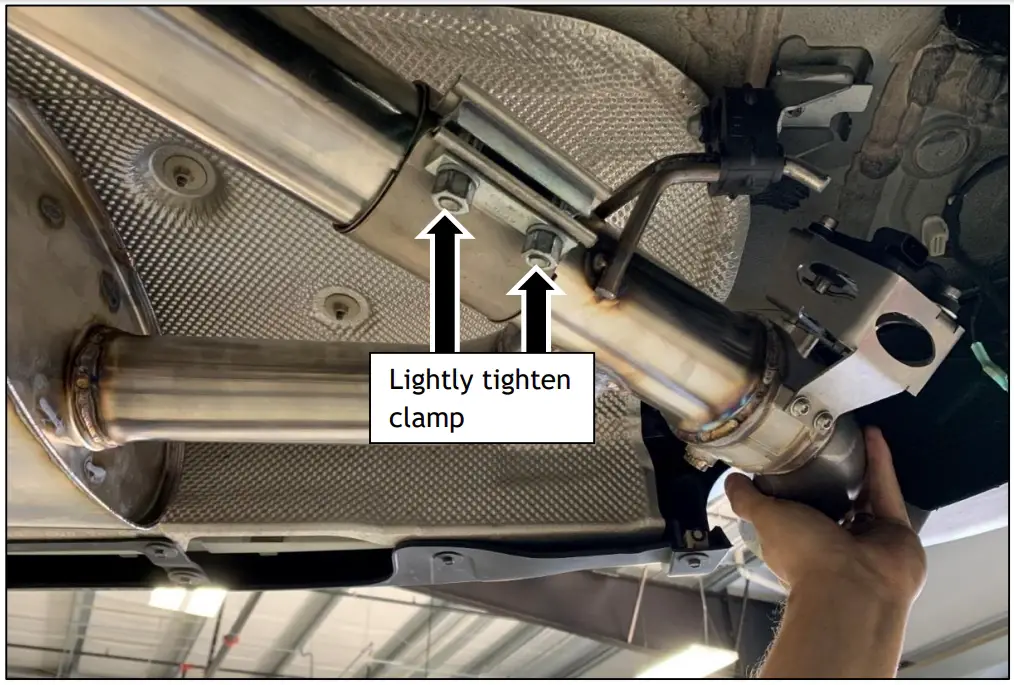
Axle Back
- Install stock hangers onto Dinan muffler system, Figure 8.
- Lift muffler assembly up in to place.
- Install the 2 nuts for the hanger mounts and tighten, Figure 9.

Figure 8: Hanger Installation
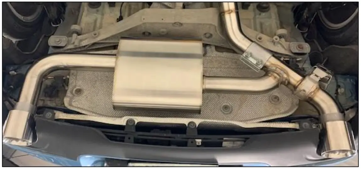
Figure 9: Exhaust Hanger Installation - Slide the wide coupler clamp over the muffler pipe, splitting the difference between the cut.
- From the rear of the vehicle:
- a. Push the exhaust system from the rear of the vehicle up and towards the front of the car and lightly tighten the coupler clamp.
- b. Final adjustment and tightening of clamps will be conducted after installation of tips.

Figure 10: Setting Muffler
Exhaust Tips
- Install the tip extensions to the end of the exhaust. Push the tip extension onto the exhaust and loosely tighten.
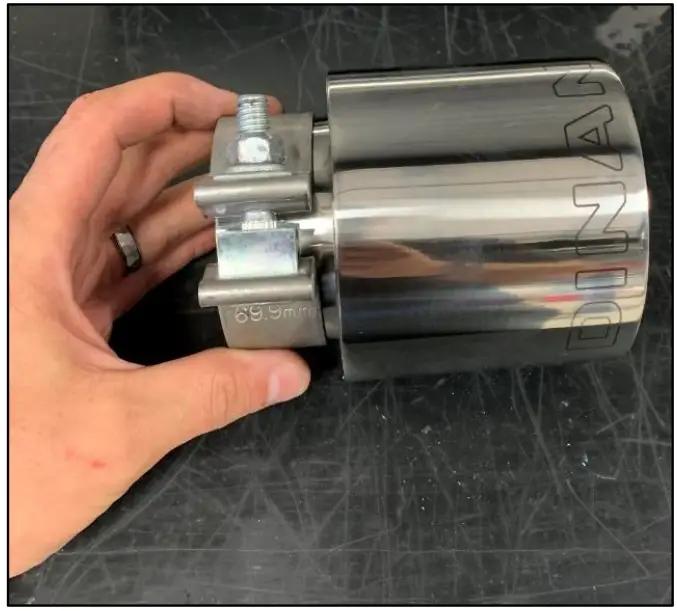
**This extension is model specific and may not be needed for your vehicle model. If tips can be positioned below without extension, do not use extension** - Slide the 69.9mm clamp onto the tip flange.
- a. Bolt shall be aligned with the DINAN logo (top side).
- b. The bolts should face towards the outside of the car. Figure 11 shows the passenger’s side tip. The driver’s side tip should have the bolt end facing the opposite direction.

Figure 11: Tip Clamp Location
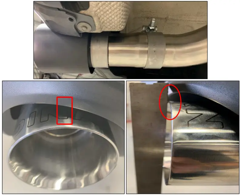
- The tips should be clocked where the middle of the first N is centered.
- a. Line up the tips where the bumper is aligned to the tip edge.
- b. Once the tips are aligned, tighten the tip clamps until tips are secure and do not move.

Figure 12: Tip Extensions and Tip Position on Vehicle
Exhaust Adjustment
Small adjustments may be needed on the Inlet Tube in order to center the tips appropriately. The following is recommended.
- Push the tips up and towards the front of the car.
- Snug fit all clamps and check tip alignment.
- Once the tips are even on both sides and spaced between the bumper to your liking, tighten the coupler clamps.
- Ensure motor is plugged into harness plug.
Clamp Torque Settings
All clamps shall be torqued to 45 ft-lbs.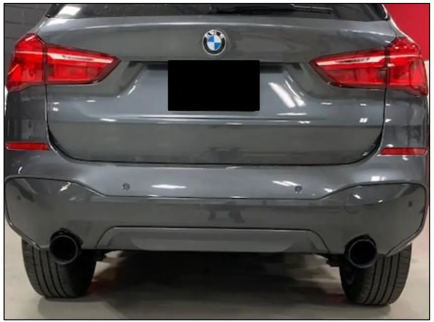
Figure 13: Tip Fitment