
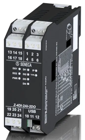
SENECA ZE-4DI-2AI-2DO multiport and multiprotocol
SENECA s.r.l. Via Austria, 26 – 35127 – PADOVA – ITALY
Tel. +39.049.8705355 – 8705359 Fax. +39.049.8706287
Web site: www.seneca.it
Technical assistance: [email protected] (IT), [email protected] (Other) Commercial reference: [email protected] (IT), [email protected] (Other)
This document is property of SENECA srl. Duplication and reproduction of its are forbidden (though partial), if not au thorized. Contents of present documentation refers to products and technologies described in it. Though we strive for reach perfection continually, all technical data contained in this document may be modified or added due to technical and commercial needs; it’s impossible eliminate mismatches and discordances completely. Contents of present documentation is anyhow subjected to periodical revision. If you have any questions don’t hesitate to contact our structure or to write us to e-mail addresses as above mentioned.
CAUTION!
UNDER ANY CIRCUMSTANCES, SENECA S.R.L. OR ITS SUPPLIERS SHALL NOT BE RESPONSIBLE FOR LOSS OF RECORDING DATA/INCOMES OR FOR CONSEQUENTIAL OR INCIDENTAL DAMAGE DUE TO NEGLECT OR RECKLESS MISHANDLING OF ZE SERIES, EVEN THOUGH SENECA IS WELL AWARE OF THESE POSSIBLE DAMAGES. SENECA, ITS SUBSIDIARIES, AFFILIATES, COMPANIES OF THE GROUP, ITS SUPPLIERS AND RETAILERS SHALL NOT GUARANTEE THAT THE FUNCTIONS WILL SATISFY COMPLETELY CUSTOMER’S EXPECTATIONS OR THAT ZE SERIES , THE FIRMWARE AND THE SOFTWARE SHALL HAVE NO ERRORS OR WORK CONTINUOUSLY.
Models comparison
| MODEL | NR 4 DIGITAL INPUTS WITH COUNTERS | NR 2 ANALOG INPUTS | NR 2 DIGITAL OUTPUT RELAYS | NR 1 ETHERNET
100 Mb | NR 2 RS485 | USB PORT |
| ZE-2AI | NO | YES | NO | YES | YES | YES |
| ZE-4DI-2AI-2DO | YES | YES | YES | YES | YES | YES |
| Z-4DI-2AI-2DO | YES | YES | YES | NO | YES | YES |
| MODEL | MODBUS RTU SLAVE
PROTOCOL | MODBUS TCP-IP SERVER
PROTOCOL | EMBEDDED WEBSERVER |
| ZE-2AI | YES | YES | YES |
| ZE-4DI-2AI-2DO | YES | YES | YES |
| Z-4DI-2AI-2DO | YES | NO | NO |
Analog Inputs
- All models include 2 analogue inputs (max. resolution 16 bit) configurable in current or voltage.
- The sampling time for each channel is configurable from 10 ms to 300 ms.
- The resolution of the ADC depends on the set acquisition speed:
- If the channel acquisition speed is < 150 ms the ADC is set with a resolution of 12 bits
- If the channel acquisition speed is >= 150 ms the ADC is set with a resolution of 16 bit
Scaling an Analog Measure
- The measure value in mV or uA is stored on registers AIN1 and AIN2, a scale measure it’s also available. The scaled measure it’s stored on AIN1 ENG and
- AIN2 ENG registers.
- For scaling a measure 4 registers are used: AIN Start Scale, AIN Stop scale, AIN ENG. Start scale and AIN ENG. Stop scale.
- For example we want to scale a 4-20mA input into a 0-10000 value:
- Start Scale must be 4 mA
- Stop Scale must be 20 mA
- Start Scale eng. must be 0
- Stop Scale eng. must be 10000
- The pure ADC value it’s stored into the AIN ADC register
Analogue measurement update time
The acquisition speed per channel is configurable from 10ms to 300ms: the higher the acquisition speed, the lower the measurement stability.
The acquisition time is considered per channel, so there will be a minimum channel update time of 20ms.
Digital Inputs
(only ZE-4DI-2AI-2DO and Z-4DI-2AI-2DO)
4 Digital inputs are available, the inputs can be configured in PNP (the input will close to +12V) or NPN (the input will close to GND) mode.
Digital Inputs filter
A filter can be used for noisy inputs, the filter value limit the maximum input frequency. For example using a filter of 5ms: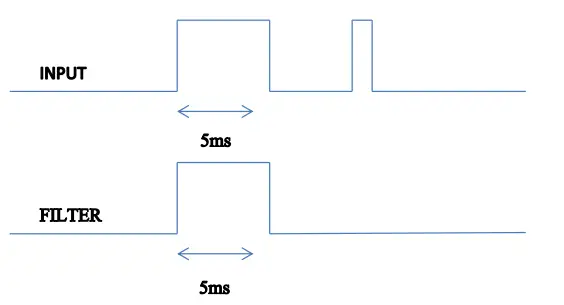 The maximum frequency can be obtained by the formula:
 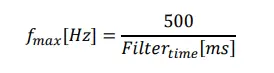 Note that the maximum frequency it’s limited to 5 KHz.
Totalizers
(only ZE-4DI-2AI-2DO and Z-4DI-2AI-2DO)
ZE-4DI-2AI-2DO and Z-4DI-2AI-2DO include 4 32 bits totalizers. The maximum frequency is 5 KHz, the input filter (see chapter 9) can be used for limit the input frequency. The Totalizer values are stored into a not volatile memory so the power can switched off without changing the Totalizer values.
Totalizers overflow
The totalizer overflow it’s at 4294967295 (hexadecimal value 0xFFFFFFFF), so another pulse will put the value to 0.
Counters
(only ZE-4DI-2AI-2DO and Z-4DI-2AI-2DO)
ZE-4DI-2AI-2DO and Z-4DI-2AI-2DO include 4 32 bits counters. The maximum frequency is 5 KHz, the input filter (see chapter 9) can be used for limit the input frequency. The Counter values are stored into a not volatile memory so the power can switched off without changing the Counter values.
Counters overflow
The totalizer overflow it’s at 4294967295 (hexadecimal value 0xFFFFFFFF), so another pulse will put the value to 0.
Digital Outputs
(only ZE-4DI-2AI-2DO and Z-4DI-2AI-2DO)
Two Digital Outputs can be set by Modbus register and by Webserver (only ZE-4DI-2AI-2DO).
The digital outputs are made by two relays (max 2A output).
Digital Outputs fail mode
The Digital Outputs support the standard Seneca out fail mod e: if there isn’t a Modbus RTU/TCP-IP communication for a configured time, the Outputs are set to a safe values. The idea behind this police is that the absence of communication means that something is wrong and therefore the outputs must be set to the fail state.
RS485 and USB Serial Communication
(only Z-4DI-2AI-2DO)
- All the models features two serial communications RS485 ports, also the USB port can be used for communication purpose.
- The RS485 ports and USB port can work all at the same time and are independent.
- The protocol supported for both ports is the Modbus RTU slave, for more information about this protocol please refer to Modbus specification website:
http://www.modbus.org/specs.php - The default configuration for RS485#1 and RS485/RS232#2 ports is:
- Modbus station address: 1
- baud rate: 38400 baud
- parity: none
- data bit: 8
- stop bit: 1
- The configuration for USB port is fixed and not configurable:
- Modbus station address: 1
- baud rate: 115200 baud
- parity: none
- data bit: 8
- stop bit: 1
Ethernet communication
(only ZE-2AI and ZE-4DI-2AI-2DO)
The ZE models include a fast Ethernet port (100Mbit), the TCP-IP integrated protocol supports:
- Static IP address or DHCP
- Gateway support
- Modbus TCP-IP server protocol (support up to 4 Modbus TCP-IP client at the same time)
- Webserver (with user / password protection)
The default configuration for the Ethernet port is:
- Static Ip address 192.168.90.101
- Modbus station address: 1
- Modbus TCP-IP client 1 port 502
- Modbus TCP-IP client 2 port 503
- Modbus TCP-IP client 3 port 504
- Modbus TCP-IP client 4 port 505
WARNING!
BEFORE CONNECT A ZE MODULE BE SURE THAT THE IP ADDRESS 192.168.90.101 IT’S NOT USED BY ANOTHER ETHERNET DEVICE.
Static IP address and DHCP
The default IP address is the static 192.168.90.101, it’s also possible to obtain an IP and a Gateway address from a DHCP server. Typically a DHCP server it’s always active into a Router (a range of address are reserved for the internal DHCP server). Using a DHCP can create problem for a connection with ZE module because the IP can change without notice (after a timeout).
Modbus RTU and Modbus TCP-IP registers map
The supported communication protocol is:
- ModBUS RTU Slave (both from RS485 port and USB port if applicable)
- Modbus TCP-IP Server (ZE-2AI and ZE-4DI-2AI-2DO models only)
- For more information on these protocols, please refer to the website http://www.modbus.org/specs.php.
Tables abbreviations
The following ModBUS functions are supported:
- Read Holding Register (function 3)
- Write Single Register (function 6)
- Write Multiple registers (function 16)
ATTENTION!
All 32-bit values are contained in 2 consecutive registers
ATTENTION!
Any 64-bit values are contained in 4 consecutive registers
ATTENTION!
Any registers with RW* (contained in flash memory) can be written a maximum of approx. 10000 times It must be the responsibility of the PLC programmer / ModBUS Master not to exceed this limit
MODBUS REGISTER TABLE
The following abbreviations are used in the register tables:
| MS | Most Significant |
| LS | Least Significant |
| MSBIT | Most Significant Bit |
| LSBIT | Least Significant Bit |
| MMSW | “Most” Most Significant Word (16bit ) |
| MSW | Most Significant Word (16bit ) |
| LSW | Least Significant Word (16bit) |
| LLSW | “Least” Least Significant Word (16bit) |
| RO | Read Only |
| RW* | Read-Write: REGISTERS CONTAINED IN FLASH MEMORY: WRITABLE AT MOST ABOUT 10000 TIMES |
| RW** | Read-Write: REGISTERS WRITABLE ONLY AFTER THE COMMAND HAS BEEN WRITTEN “ENABLE WRITE CUSTOM ENERGIES=49616” |
| UNSIGNED 16 BIT | Unsigned integer register that can take values from 0 to 65535 |
| SIGNED 16 BIT | Integer register with sign that can take values from -32768 to +32767 |
| UNSIGNED 32 BIT | Unsigned integer register that can take values from 0 to 4294967296 |
| SIGNED 32 BIT | Integer register with sign that can take values from -2147483648 to 2147483647 |
| UNSIGNED 64 BIT | Unsigned integer register that can take values from 0 to 18,446,744,073,709,551,615 |
| SIGNED 64 BIT | Signed integer register that can take values from -2^63 to 2^63-1 |
| FLOAT 32 BIT | 32-bit, single-precision floating-point register (IEEE 754) https://en.wikipedia.org/wiki/IEEE_754 |
| BIT | Boolean register, which can take the values 0 (false) or 1 (true) |
NUMBERING OF ‘0 BASED’ OR ‘1 BASED’ MODBUS ADDRESSES
Holding registers according to the ModBUS standard are addressable from 0 to 65535, there are 2 different address numbering conventions: ‘0 BASED’ and ‘1 BASED’.For the sake of clarity, Seneca shows its register tables in both conventions.
ATTENTION!
CAREFULLY READ THE DOCUMENTATION OF THE MODBUS MASTER DEVICE IN ORDER TO UNDERSTAND WHICH OF THE TWO CONVENTIONS THE MANUFACTURER HAS DECIDED TO USE.
NUMBERING OF MODBUS ADDRESSES WITH ‘0 BASED’ CONVENTION
The numbering is of the type:
| INDIRIZZO MODBUS HOLDING REGISTER (OFFSET) | SIGNIFICANCE |
| 0 | FIRST REGISTER |
| 1 | SECOND REGISTER |
| 2 | THIRD REGISTER |
| 3 | FOURTH REGISTER |
| 4 | FIFTH REGISTER |
Thus, the first register is located at address 0.
In the following tables, this convention is indicated by “OFFSET ADDRESS”.
MODBUS ADDRESS NUMBERING WITH ‘1 BASED’ CONVENTION (STANDARD)
The numbering is that established by the Modbus consortium and is of the type:
| MODBUS ADDRESS HOLDING REGISTER 4x | MEANING |
| 40001 | FIRST REGISTER |
| 40002 | SECOND REGISTER |
| 40003 | THIRD REGISTER |
| 40004 | FOURTH REGISTER |
| 40005 | FIFTH REGISTER |
In the following tables, this convention is referred to as ‘ADDRESS 4x’ because a 4 is added to the address so that the first ModBUS register is 40001.
A further convention where the number 4 is omitted in front of the register address is also possible:
| MODBUS HOLDING ADDRESS WITHOUT 4x | MEANING |
| 1 | FIRST REGISTER |
| 2 | SECOND REGISTER |
| 3 | THIRD REGISTER |
| 4 | FOURTH REGISTER |
| 5 | FIFTH REGISTER |
BIT CONVENTION WITHIN A MODBUS HOLDING REGISTER
A ModBUS Holding Register consists of 16 bits with the following convention:
| BIT 15 | BIT 14 | BIT 13 | BIT 12 | BIT 11 | BIT 10 | BIT 9 | BIT 8 | BIT 7 | BIT 6 | BIT 5 | BIT 4 | BIT 3 | BIT 2 | BIT 1 | BIT 0 |
For example, if the register value in decimal is 12300 the value 12300 in hexadecimal applies: 0x300C hexadecimal 0x300C in binary value applies: 11 0000 0000 1100 So, using the above convention we get:
| BIT 15 | BIT 14 | BIT 13 | BIT 12 | BIT 11 | BIT 10 | BIT 9 | BIT 8 | BIT 7 | BIT 6 | BIT 5 | BIT 4 | BIT 3 | BIT 2 | BIT 1 | BIT 0 |
| 0 | 0 | 1 | 1 | 0 | 0 | 0 | 0 | 0 | 0 | 0 | 0 | 1 | 1 | 0 | 0 |
CONVENTION OF MSB and LSB BYTES WITHIN A MODBUS HOLDING REGISTER
A ModBUS Holding Register consists of 16 bits with the following convention:
| BIT 15 | BIT 14 | BIT 13 | BIT 12 | BIT 11 | BIT 10 | BIT 9 | BIT 8 | BIT 7 | BIT 6 | BIT 5 | BIT 4 | BIT 3 | BIT 2 | BIT 1 | BIT 0 |
LSB Byte (Least Significant Byte) is defined as the 8 bits ranging from Bit 0 to Bit 7 inclusive, MSB Byte (Most Significant Byte) is defined as the 8 bits ranging from Bit 8 to Bit 15 inclusive:
| BIT 15 | BIT 14 | BIT 13 | BIT 12 | BIT 11 | BIT 10 | BIT 9 | BIT 8 | BIT 7 | BIT 6 | BIT 5 | BIT 4 | BIT 3 | BIT 2 | BIT 1 | BIT 0 |
| BYTE MSB | BYTE LSB | ||||||||||||||
REPRESENTATION OF A 32-BIT VALUE IN TWO CONSECUTIVE MODBUS HOLDING REGISTERS
- The representation of a 32-bit value in the Holding Registers in ModBUS is done using 2 consecutive Holding Registers (one Holding Register is 16 bits).
- To obtain the 32-bit value, two consecutive registers must therefore be read:
- For example if register 40064 holds the most significant 16 bits (MSW) while register 40065 holds the least significant 16 bits (LSW) the 32-bit value is obtained by composing the 2 registers:
BIT 15 BIT 14 BIT 13 BIT 12 BIT 11 BIT 10 BIT 9 BIT 8 BIT 7 BIT 6 BIT 5 BIT 4 BIT 3 BIT 2 BIT 1 BIT 0 40064 MOST SIGNIFICANT WORD BIT 15 BIT 14 BIT 13 BIT 12 BIT 11 BIT 10 BIT 9 BIT 8 BIT 7 BIT 6 BIT 5 BIT 4 BIT 3 BIT 2 BIT 1 BIT 0 40065 LEAST SIGNIFICANT WORD
32 = + ( ∗ 65536)
In the read registers, it is possible to exchange the most significant word for the least significant one, so it is possible to get 40064 as LSW and 40065 as MSW.
TIPI DI DATO FLOATING POINT A 32 BIT (IEEE 754)
The IEEE 754 standard (https://en.wikipedia.org/wiki/IEEE_754) defines the format for the representation of floating-point numbers. As already mentioned, since it is a 32-bit data type, its representation occupies two 16-bit holding registers. To obtain a binary/hexadecimal conversion of a Floating point value, you can refer to an online converter at this address: http://www.h-schmidt.net/FloatConverter/IEEE754.html
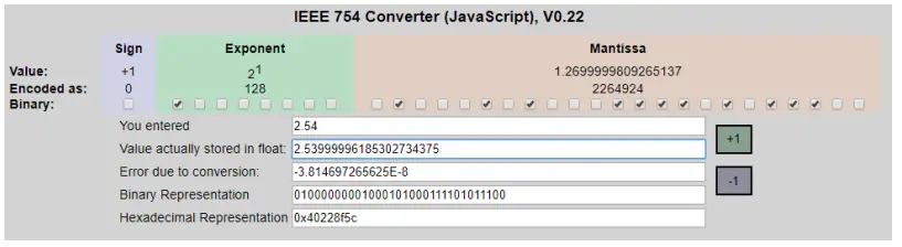
Using the last representation, the value 2.54 is represented in 32 bits as: 0x40228F5C
Since we have 16-bit registers available, the value must be divided into MSW and LSW: 0x4022 (16418 decimal) are the 16 most significant bits (MSW) while 0x8F5C (36700 decimal) are the 16 least significant bits (LSW).
Modbus TCP-IP and Modbus RTU register addresses ZE -4DI- 2AI-2DO and Z-4DI-2AI- 2DO
| ADDRESS (4x) | OFFSET | REGISTER | ORDER | CHANNEL | DESCRIPTION | R/W | TYPE |
| 40001 | 0 | Machine ID | – | – | Identification Code | R | Unsigned 16bits |
| 40002 | 1 | FW Code | – | – | FW Code revision | R | Unsigned 16bits |
| 40003 | 2 | Status | – | – | bit 0=OUTPUT FAIL bit 1=AIN1 underflow bit 2=AIN1 overflow bit 3=AIN2 underflow bit 4=AIN2 overflow bit 15..8= Not used | R | Unsigned 16bits |
| 40004 | 3 | Analog Input | – | 1 | Analog input 1 Electrical value: mV or uA | R | Unsigned 16bits |
| 40005 | 4 | Analog Input Scaled Value | – | 1 | Analog input 1 Scaled value | R | Unsigned 16bits |
| 40006 | 5 | Analog Input | – | 2 | Analog input 2 Electrical value: mV or uA | R | Unsigned 16bits |
| 40007 | 6 | Analog Input Scaled Value | – | 2 | Analog input 2 Scaled value | R | Unsigned 16bits |
| 40008 | 7 | OUTPUTS | – | 1 and 2 | Bit 0=OUTPUT1 Bit 1=OUTPUT2 | R/W | Unsigned 16bits |
| 40009 | 8 | OUTPUT1 | – | 1 | 0=OUTPUT NOT EXCITED 1=OUTPUT EXCITED | R/W | Unsigned 16bits |
| 40010 | 9 | OUTPUT2 | – | 2 | 0=OUTPUT NOT EXCITED 1=OUTPUT EXCITED | R/W | Unsigned 16bits |
| 40011 | 10 | INPUTS | – | 1 and 2 | Bit 0=INPUT1 Bit 1=INPUT2 Bit 2=INPUT3 Bit 3=INPUT4 | R | Unsigned 16bits |
| 40012 | 11 | INPUT 1 | – | 1 | 0=INPUT LOW 1=INPUT HIGH | R | Unsigned 16bits |
| 40013 | 12 | INPUT 2 | – | 2 | 0=INPUT LOW 1=INPUT HIGH | R | Unsigned 16bits |
| 40014 | 13 | INPUT3 | – | 3 | 0=INPUT LOW 1=INPUT HIGH | R | Unsigned 16bits |
| ADDRESS (4x) | OFFSET | REGISTER | ORDER | CHANNEL | DESCRIPTION | R/W | TYPE |
| 40014 | 13 | INPUT4 | – | 4 | 0=INPUT LOW 1=INPUT HIGH | R | Unsigned 16bits |
| 40016 | 15 | TOTALIZER 1 | MSW | 1 | Totalizer 1 | R/W | Unsigned 32 bits |
| 40017 | 16 | LSW | |||||
| 40018 | 17 | TOTALIZER 2 | MSW | 2 | Totalizer 2 | R/W | Unsigned 32 bits |
| 40019 | 18 | LSW | |||||
| 40020 | 19 | TOTALIZER 3 | MSW | 3 | Totalizer 3 | R/W | Unsigned 32 bits |
| 40021 | 20 | LSW | |||||
| 40022 | 21 | TOTALIZER 4 | MSW | 4 | Totalizer 4 | R/W | Unsigned 32 bits |
| 40023 | 22 | LSW | |||||
| 40024 | 23 | COUNTER 1 | MSW | 1 | Counter 1 | R/W | Unsigned 32 bits |
| 40025 | 24 | LSW | |||||
| 40026 | 25 | COUNTER 2 | MSW | 2 | Counter 2 | R/W | Unsigned 32 bits |
| 40027 | 26 | LSW | |||||
| 40028 | 27 | COUNTER 3 | MSW | 3 | Counter 3 | R/W | Unsigned 32 bits |
| 40029 | 28 | LSW | |||||
| 40030 | 29 | COUNTER 4 | MSW | 4 | Counter 4 | R/W | Unsigned 32 bits |
| 40031 | 30 | LSW | |||||
| 40032 | 31 | IP ADDR. 0 | – | – | Actual IP address, 1st number | R | Unsigned 16 bits |
| 40033 | 32 | IP ADDR. 1 | – | – | Actual IP address, 2nd number | R | Unsigned 16 bits |
| 40034 | 33 | IP ADDR. 2 | – | – | Actual IP address, 3rd number | R | Unsigned 16 bits |
| 40035 | 34 | IP ADDR. 3 | – | – | Actual IP address, 4th number | R | Unsigned 16 bits |
| 40036 | 35 | IP MASK 0 | – | – | Actual IP mask, 1st number | R | Unsigned 16 bits |
| 40037 | 36 | IP MASK 1 | – | – | Actual IP mask, 2nd number | R | Unsigned 16 bits |
| 40038 | 37 | IP MASK 2 | – | – | Actual IP mask, 3rd number | R | Unsigned 16 bits |
| 40039 | 38 | IP MASK 3 | – | – | Actual IP mask, 4th number | R | Unsigned 16 bits |
| 40040 | 39 | IP GATEWAY 0 | – | – | Actual IP gateway, 1st number | R | Unsigned 16 bits |
| 40041 | 40 | IP GATEWAY 1 | – | – | Actual IP gateway, 2nd number | R | Unsigned 16 bits |
| 40042 | 41 | IP GATEWAY 2 | – | – | Actual IP gateway , 3rd number | R | Unsigned 16 bits |
| 40043 | 42 | IP GATEWAY 3 | – | – | Actual IP gateway , 4th number | R | Unsigned 16 bits |
| 40044 | 43 | MAC ADDR.0 | – | – | MAC address, | R | Unsigned 16 bits |
| -40001 | 1st number (hexadecimal interpretation) |
| ADDRESS (4x) | OFFSET | REGISTER | ORDER | CHANNEL | DESCRIPTION | R/W | TYPE |
| 40045 | 44 | MAC ADDR.1 | – | – | MAC address, 2nd number (hexadecimal interpretation) | R | Unsigned 16 bits |
| 40046 | 45 | MAC ADDR.2 | MAC address, 3rd number (hexadecimal interpretation) | R | Unsigned 16 bits | ||
| 40047 | 46 | AIN1 ADC | – | – | Analog input 1 ADC value | R | Unsigned 16 bits |
| 40048 | 47 | AIN2 ADC | Analog input 2 ADC value | R | Unsigned 16 bits | ||
| 40101 | 100 | AIN INPUT SPEED | – | – | Analog input speed from 10 to 300 [ms] for channel | R/W | Unsigned 16 bits |
| 40102 | 101 | NOT USED | – | – | – | R/W | Unsigned 16 bits |
| 40103 | 102 | AIN1 TYPE | – | 1 | Analog input 1 mode 0=mA 1=mV | R/W | Unsigned 16 bits |
| 40104 | 103 | AIN1 START SCALE | – | 1 | Start scale (electrical) for analog input 1: expressed in mV or uA | R/W | Unsigned 16 bits |
| 40105 | 104 | AIN1 STOP SCALE | – | 1 | Stop scale (electrical) for analog input 1: expressed in mV or uA | R/W | Unsigned 16 bits |
| 40106 | 105 | AIN1 ENG. START SCALE | – | 1 | Start scale (engineering) for analog input 1: expressed in mV or uA | R/W | Unsigned 16 bits |
| 40107 | 106 | AIN1 ENG. STOP SCALE | – | 1 | Stop scale (engineering) for analog input 1: expressed in mV or uA | R/W | Unsigned 16 bits |
| 40108 | 107 | NOT USED | – | – | – | R/W | Unsigned 16 bits |
| 40103 | 102 | AIN2 TYPE | – | 2 | Analog input 2 mode 0=mA 1=mV | R/W | Unsigned 16 bits |
| 40104 | 103 | AIN2 START SCALE | – | 2 | Start scale (electrical) for analog input 2: expressed in mV or uA | R/W | Unsigned 16 bits |
| 40105 | 104 | AIN2 STOP SCALE | – | 2 | Stop scale (electrical) for | R/W | Unsigned 16 bits |
| ADDRESS (4x) | OFFSET | REGISTER | ORDER | CHANNEL | DESCRIPTION | R/W | TYPE |
| analog input 2: expressed in mV or uA | |||||||
| 40106 | 105 | AIN2 ENG. START SCALE | – | 2 | Start scale (engineering) for analog input 2: expressed in mV or uA | R/W | Unsigned 16 bits |
| 40107 | 106 | AIN2 ENG. STOP SCALE | – | 2 | Stop scale (engineering) for analog input 2: expressed in mV or uA | R/W | Unsigned 16 bits |
| 40114 | 113 | DIN1 FILTER | – | 1 | Digital input 1 filter in ms | R/W | Unsigned 16 bits |
| 40115 | 114 | DIN2 FILTER | – | 2 | Digital input 2 filter in ms | R/W | Unsigned 16 bits |
| 40116 | 115 | DIN3 FILTER | – | 3 | Digital input 3 filter in ms | R/W | Unsigned 16 bits |
| 40117 | 116 | DIN4 FILTER | – | 4 | Digital input 4 filter in ms | R/W | Unsigned 16 bits |
| 40118 | 117 | DIN NPN/PNP | – | – | Digital input type: 0=NPN, 1=PNP | R/W | Unsigned 16 bits |
| 40119 | 118 | DOUT FAIL MODE | – | – | Digital output fail mode: 0=disabled 1=enabled | R/W | Unsigned 16 bits |
| 40120 | 119 | DOUT FAIL TIMEOUT | – | – | Timeout start fail for digital outputs (in seconds) | R/W | Unsigned 16 bits |
| 40121 | 120 | DOUT1 FAIL VALUE | – | – | Digital output1 value in fail case. | R/W | Unsigned 16 bits |
| 40122 | 121 | DOUT2 FAIL VALUE | – | – | Digital output2 value in fail case. | R/W | Unsigned 16 bits |
| 40123 | 122 | IP DHCP | – | – | 0=Ethernet IP is static 1=Ethernet IP is acquired from a DHCP server | R/W | Unsigned 16 bits |
| 40124 | 123 | IP ADDRESS 0-1 | – | – | Most significant byte=IP address 0 (if static) Less significant byte=IP address 1 (if static) | R/W | Unsigned 16 bits |
| 40125 | 124 | IP ADDRESS 2-3 | – | – | Most significant byte=IP address 2 (if static). Less significant | R/W | Unsigned 16 bits |
| ADDRESS (4x) | OFFSET | REGISTER | ORDER | CHANNEL | DESCRIPTION | R/W | TYPE |
| byte=IP address 3 (if static) | |||||||
| 40126 | 125 | IP MASK 0-1 | – | – | Most significant byte=IP mask 0 (if static) Less significant byte=IP mask 1 (if static) | R/W | Unsigned 16 bits |
| 40127 | 126 | IP MASK 2-3 | – | – | Most significant byte=IP mask 2 (if static) Less significant byte=IP mask 3 (if static) | R/W | Unsigned 16 bits |
| 40128 | 127 | IP GATEWAY 0-1 | – | – | Most significant byte=IP gateway 0 (if static). Less significant byte=IP gateway 1 (if static). | R/W | Unsigned 16 bits |
| 40129 | 128 | IP GATEWAY 2-3 | – | – | Most significant byte=IP gateway 2 (if static). Less significant byte=IP gateway 3 (if static). | R/W | Unsigned 16 bits |
| 40130 | 129 | TCP/IP PORT 1 | – | – | Port of TCP/IP client 1 | R/W | Unsigned 16 bits |
| 40131 | 130 | TCP/IP TMO 1 | – | – | Timeout of TCP/IP port 1 (in ms) | R/W | Unsigned 16 bits |
| 40132 | 131 | TCP/IP ADDR 1 | – | – | Modbus address for TCP/IP port 1 (MSB) | R/W | Unsigned 16 bits |
| 40133 | 132 | 485#1 BAUDRATE | – | – | Baudrate value for RS485 port 1 (baudrate /10, so write 3840 for 38400 baud etc…) | R/W | Unsigned 16 bits |
| 40134 | 133 | 485#1 PARITY / STOP BITS | – | – | PARITY=MSB (0=no parity, 1=odd, 2=even) STOP BITS=LSB (0=1 stop bit, 1=2 stop bits) | R/W | Unsigned 16 bits |
| ADDRESS (4x) | OFFSET | REGISTER | ORDER | CHANNEL | DESCRIPTION | R/W | TYPE |
| 40135 | 134 | 485#1 TIMEOUT | – | – | Timeout of RS485 port 1 in ms | R/W | Unsigned 16 bits |
| 40136 | 135 | 485#2 BAUDRATE | – | – | Baudrate value for RS485 port 2 (baudrate /10, so write 3840 for 38400 baud etc…) | R/W | Unsigned 16 bits |
| 40137 | 136 | 485#2 PARITY / STOP BITS | – | – | PARITY=MSB (0=no parity, 1=odd, 2=even) STOP BITS=LSB (0=1 stop bit, 1=2 stop bits) | R/W | Unsigned 16 bits |
| 40138 | 137 | 485#2 TIMEOUT | – | – | Timeout of RS485 port 2 in ms | R/W | Unsigned 16 bits |
| 40139 | 138 | 485#1 ADDR 485#2 ADDR | – | – | MODBUS ADDR. 485#1=MSB MODBUS ADDR. 485#2=LSB | R/W | Unsigned 16 bits |
| 40901 | 900 | TCP/IP PORT 2 | – | – | Port of TCP/IP client 2 | R/W | Unsigned 16 bits |
| 40902 | 901 | TCP/IP TMO 2 | – | – | Timeout of TCP/IP port 2 (in ms) | R/W | Unsigned 16 bits |
| 40903 | 902 | TCP/IP ADDR 2 | – | – | Modbus address for TCP/IP port 2 (MSB) | R/W | Unsigned 16 bits |
| 40904 | 903 | TCP/IP PORT 3 | – | – | Port of TCP/IP client 3 | R/W | Unsigned 16 bits |
| 40905 | 904 | TCP/IP TMO 3 | – | – | Timeout of TCP/IP port 3 (in ms) | R/W | Unsigned 16 bits |
| 40906 | 905 | TCP/IP ADDR 3 | – | – | Modbus address for TCP/IP port 3 (MSB) | R/W | Unsigned 16 bits |
| 40907 | 906 | TCP/IP PORT 4 | – | – | Port of TCP/IP client 4 | R/W | Unsigned 16 bits |
| 40908 | 907 | TCP/IP TMO 4 | – | – | Timeout of TCP/IP port 4 (in ms) | R/W | Unsigned 16 bits |
| 40909 | 908 | TCP/IP ADDR 4 | – | – | Modbus address for TCP/IP port 4 (MSB) | R/W | Unsigned 16 bits |
| 40951 | 950 | WEBSERVER PORT | – | – | Webserver Port | R/W | Unsigned 16 bits |
| 41001 | 1000 | COMMAND | – | – | Command Register | R/W | Unsigned 16 bits |
| 41002 | 1001 | – | – | R/W |
| ADDRESS (4x) | OFFSET | REGISTER
COMMAND AUX1 | ORDER | CHANNEL | DESCRIPTION
Auxiliary 1 Command Register | R/W | TYPE
Unsigned 16 bits |
| 41003 | 1002 | COMMAND AUX2 | – | – | Auxiliary 2 Command Register | R/W | Unsigned 16 bits |
The Command register (address 41001) allows commands to be executed.
Please note that the following numeric commands are written in hexadecimal format!
- to save the EEPROM configuration, write 0x0001 to register 41001
- to reset the device, write 0x0005 to reg. 41001
- to load default settings, write 0x0006 to register 41001
- to clear totaliser 1, write 0x0007 to register 41001
- to clear totaliser 2, write 0x0008 to register 41001
- to clear totaliser 3, write 0x0009 to register 41001
- to clear totaliser 4, write 0x000A to register 41001
- to clear counter 1, write 0x000B to register 41001
- to clear counter 2, write 0x000C
- to clear counter 3, write 0x000D
- to clear counter 4, write 0x000E
- to set a 32-bit value in totalizer 1, write the desired value to register 41002 (MSW of the 32-bit value)-41003 (LSW of the 32-bit value), then write 0x000F to register 41001
- to set a 32-bit value in totaliser 2, write the desired value to register 41002 (MSW of 32bit value)-41003 (LSW of 32bit value), then write 0x0010 to register 41001.
- to set a 32-bit value in totaliser 3, write the desired value to reg. 41002 (MSW of 32bit value)-41003 (LSW of 32bit value), then write 0x0011 to reg. 41001.
- to set a 32-bit value in totaliser 4, write the desired value to reg. 41002 (MSW of 32bit value)-41003 (LSW of 32bit value), then write 0x0012 to reg. 41001.
- to set a 32-bit value in counter 1, write the desired value to reg. 41002 (MSW of 32bit value)-41003 (LSW of 32bit value), then write 0x0013 to reg. 41001.
- to set a 32-bit value in counter 2, write the desired value to reg. 41002 (MSW of 32bit value)-41003 (LSW of 32bit value), then write 0x0014 to reg. 41001.
- to set a 32-bit value in counter 3, write the desired value to reg. 41002 (MSW of 32bit value)-41003 (LSW of 32bit value), then write 0x0015 to reg. 41001.
- to set a 32 bit value in counter 4, write the desired value to reg. 41002 (MSW of 32bit value)-41003 (LSW of 32bit value), then write 0x0016 to reg. 41001
Modbus TCP-IP and Modbus RTU register addresses ZE-2AI
| ADDRESS (4x) | OFFSET | REGISTER | ORDER | CHANNEL | DESCRIPTION | R/W | TYPE |
| 40001 | 0 | Machine ID | – | – | Identification Code | R | Unsigned 16bits |
| 40002 | 1 | FW Code | – | – | FW Code revision | R | Unsigned 16bits |
| 40003 | 2 | Status | – | – | bit 0=OUTPUT FAIL bit 1=AIN1 underflow bit 2=AIN1 overflow bit 3=AIN2 underflow bit 4=AIN2 overflow bit 15..8= Not used | R | Unsigned 16bits |
| 40004 | 3 | Analog Input | – | 1 | Analog input 1 Electrical value: mV or uA | R | Unsigned 16bits |
| 40005 | 4 | Analog Input Scaled Value | – | 1 | Analog input 1 Scaled value | R | Unsigned 16bits |
| 40006 | 5 | Analog Input | – | 2 | Analog input 2 Electrical value: mV or uA | R | Unsigned 16bits |
| 40007 | 6 | Analog Input Scaled Value | – | 2 | Analog input 2 Scaled value | R | Unsigned 16bits |
| 40008 | 7 | NOT USED | – | – | – | R/W | Unsigned 16bits |
| 40009 | 8 | NOT USED | – | – | – | R/W | Unsigned 16bits |
| 40010 | 9 | NOT USED | – | – | – | R/W | Unsigned 16bits |
| 40011 | 10 | NOT USED | – | – | – | R/W | Unsigned 16bits |
| 40012 | 11 | NOT USED NOT USED | – – | – – | – – | R | Unsigned 16bits |
| 40013 | 12 | NOT USED NOT USED | – – | – – | – – | R | Unsigned 16bits |
| 40014 | 13 | NOT USED NOT USED | – – | – – | – – | R | Unsigned 16bits |
| 40014 | 13 | NOT USED | – | – | – | R | Unsigned 16bits |
| 40016 | 15 | NOT USED | MSW | – | – | R/W | Unsigned 32 bits |
| 40017 | 16 | LSW | |||||
| 40018 | 17 | NOT USED | MSW | – | – | R/W | Unsigned 32 bits |
| 40019 | 18 | LSW | |||||
| 40020 | 19 | NOT USED | MSW | – | – | R/W |
| ADDRESS (4x) | OFFSET | REGISTER | ORDER | CHANNEL | DESCRIPTION | R/W | TYPE |
| 40021 | 20 | LSW | Unsigned 32 bits | ||||
| 40022 | 21 | NOT USED | MSW | – | – | R/W | Unsigned 32 bits |
| 40023 | 22 | LSW | |||||
| 40024 | 23 | NOT USED | MSW | – | – | R/W | Unsigned 32 bits |
| 40025 | 24 | LSW | |||||
| 40026 | 25 | NOT USED | MSW | – | – | R/W | Unsigned 32 bits |
| 40027 | 26 | LSW | |||||
| 40028 | 27 | NOT USED | MSW | – | – | R/W | Unsigned 32 bits |
| 40029 | 28 | LSW | |||||
| 40030 | 29 | NOT USED | MSW | – | – | R/W | Unsigned 32 bits |
| 40031 | 30 | LSW | |||||
| 40032 | 31 | IP ADDR. 0 | – | – | Actual IP address, 1st number | R | Unsigned 16 bits |
| 40033 | 32 | IP ADDR. 1 | – | – | Actual IP address, 2nd number | R | Unsigned 16 bits |
| 40034 | 33 | IP ADDR. 2 | – | – | Actual IP address, 3rd number | R | Unsigned 16 bits |
| 40035 | 34 | IP ADDR. 3 | – | – | Actual IP address, 4th number | R | Unsigned 16 bits |
| 40036 | 35 | IP MASK 0 | – | – | Actual IP mask, 1st number | R | Unsigned 16 bits |
| 40037 | 36 | IP MASK 1 | – | – | Actual IP mask, 2nd number | R | Unsigned 16 bits |
| 40038 | 37 | IP MASK 2 | – | – | Actual IP mask, 3rd number | R | Unsigned 16 bits |
| 40039 | 38 | IP MASK 3 | – | – | Actual IP mask, 4th number | R | Unsigned 16 bits |
| 40040 | 39 | IP GATEWAY 0 | – | – | Actual IP gateway, 1st number | R | Unsigned 16 bits |
| 40041 | 40 | IP GATEWAY 1 | – | – | Actual IP gateway, 2nd number | R | Unsigned 16 bits |
| 40042 | 41 | IP GATEWAY 2 | – | – | Actual IP gateway , 3rd number | R | Unsigned 16 bits |
| 40043 | 42 | IP GATEWAY 3 | – | – | Actual IP gateway , 4th number | R | Unsigned 16 bits |
| 40044 | 43 | MAC ADDR.0 | – | – | MAC address, | R | Unsigned 16 bits |
| -40001 | 1st number (hexadecimal interpretation) | ||||||
| 40045 | 44 | MAC ADDR.1 | – | – | MAC address, 2nd number (hexadecimal interpretation) | R | Unsigned 16 bits |
| 40046 | 45 | MAC ADDR.2 | MAC address, 3rd number (hexadecimal interpretation) | R | Unsigned 16 bits | ||
| 40047 | 46 | AIN1 ADC | – | – | Analog input 1 ADC value | R | Unsigned 16 bits |
| 40048 | 47 | AIN2 ADC | Analog input 2 ADC value | R | Unsigned 16 bits | ||
| 40101 | 100 | AIN INPUT SPEED | – | – | Analog input speed from 10 to 300 [ms] for channel | R/W | Unsigned 16 bits |
| ADDRESS (4x) | OFFSET | REGISTER | ORDER | CHANNEL | DESCRIPTION | R/W | TYPE |
| 40102 | 101 | NOT USED | – | – | – | R/W | Unsigned 16 bits |
| 40103 | 102 | AIN1 TYPE | – | 1 | Analog input 1 mode 0=mA 1=mV | R/W | Unsigned 16 bits |
| 40104 | 103 | AIN1 START SCALE | – | 1 | Start scale (electrical) for analog input 1: expressed in mV or uA | R/W | Unsigned 16 bits |
| 40105 | 104 | AIN1 STOP SCALE | – | 1 | Stop scale (electrical) for analog input 1: expressed in mV or uA | R/W | Unsigned 16 bits |
| 40106 | 105 | AIN1 ENG. START SCALE | – | 1 | Start scale (engineering) for analog input 1: expressed in mV or uA | R/W | Unsigned 16 bits |
| 40107 | 106 | AIN1 ENG. STOP SCALE | – | 1 | Stop scale (engineering) for analog input 1: expressed in mV or uA | R/W | Unsigned 16 bits |
| 40108 | 107 | NOT USED | – | – | – | R/W | Unsigned 16 bits |
| 40103 | 102 | AIN2 TYPE | – | 2 | Analog input 2 mode 0=mA 1=mV | R/W | Unsigned 16 bits |
| 40104 | 103 | AIN2 START SCALE | – | 2 | Start scale (electrical) for analog input 2: expressed in mV or uA | R/W | Unsigned 16 bits |
| 40105 | 104 | AIN2 STOP SCALE | – | 2 | Stop scale (electrical) for analog input 2: expressed in mV or uA | R/W | Unsigned 16 bits |
| 40106 | 105 | AIN2 ENG. START SCALE | – | 2 | Start scale (engineering) for analog input 2: expressed in mV or uA | R/W | Unsigned 16 bits |
| 40107 | 106 | AIN2 ENG. STOP SCALE | – | 2 | Stop scale (engineering) for analog input 2: expressed in mV or uA | R/W | Unsigned 16 bits |
| 40114 | 113 | NOT USED | – | – | – | R/W | Unsigned 16 bits |
| ADDRESS (4x) | OFFSET | REGISTER | ORDER | CHANNEL | DESCRIPTION | R/W | TYPE |
| 40115 | 114 | NOT USED | – | – | – | R/W | Unsigned 16 bits |
| 40116 | 115 | NOT USED | – | – | – | R/W | Unsigned 16 bits |
| 40117 | 116 | NOT USED | – | – | – | R/W | Unsigned 16 bits |
| 40118 | 117 | NOT USED | – | – | – | R/W | Unsigned 16 bits |
| 40119 | 118 | NOT USED | – | – | – | R/W | Unsigned 16 bits |
| 40120 | 119 | NOT USED | – | – | – | R/W | Unsigned 16 bits |
| 40121 | 120 | NOT USED | – | – | – | R/W | Unsigned 16 bits |
| 40122 | 121 | NOT USED | – | – | – | R/W | Unsigned 16 bits |
| 40123 | 122 | IP DHCP | – | – | 0=Ethernet IP is static 1=Ethernet IP is acquired from a DHCP server | R/W | Unsigned 16 bits |
| 40124 | 123 | IP ADDRESS 0-1 | – | – | Most significant byte=IP address 0 (if static) Less significant byte=IP address 1 (if static) | R/W | Unsigned 16 bits |
| 40125 | 124 | IP ADDRESS 2-3 | – | – | Most significant byte=IP address 2 (if static). Less significant byte=IP address 3 (if static) | R/W | Unsigned 16 bits |
| 40126 | 125 | IP MASK 0-1 | – | – | Most significant byte=IP mask 0 (if static) Less significant byte=IP mask 1 (if static) | R/W | Unsigned 16 bits |
| 40127 | 126 | IP MASK 2-3 | – | – | Most significant byte=IP mask 2 (if static) Less significant byte=IP mask 3 (if static) | R/W | Unsigned 16 bits |
| 40128 | 127 | IP GATEWAY 0-1 | – | – | Most significant byte=IP gateway 0 (if static). Less significant byte=IP gateway 1 (if static). | R/W | Unsigned 16 bits |
| 40129 | 128 | IP GATEWAY 2-3 | – | – | Most significant byte=IP gateway 2 (if static). Less significant byte=IP | R/W | Unsigned 16 bits |
| ADDRESS (4x) | OFFSET | REGISTER | ORDER | CHANNEL | DESCRIPTION | R/W | TYPE |
| gateway 3 (if static). | |||||||
| 40130 | 129 | TCP/IP PORT 1 | – | – | Port of TCP/IP client 1 | R/W | Unsigned 16 bits |
| 40131 | 130 | TCP/IP TMO 1 | – | – | Timeout of TCP/IP port 1 (in ms) | R/W | Unsigned 16 bits |
| 40132 | 131 | TCP/IP ADDR 1 | – | – | Modbus address for TCP/IP port 1 (MSB) | R/W | Unsigned 16 bits |
| 40133 | 132 | 485#1 BAUDRATE | – | – | Baudrate value for RS485 port 1 (baudrate /10, so write 3840 for 38400 baud etc…) | R/W | Unsigned 16 bits |
| 40134 | 133 | 485#1 PARITY / STOP BITS | – | – | PARITY=MSB (0=no parity, 1=odd, 2=even) STOP BITS=LSB (0=1 stop bit, 1=2 stop bits) | R/W | Unsigned 16 bits |
| 40135 | 134 | 485#1 TIMEOUT | – | – | Timeout of RS485 port 1 in ms | R/W | Unsigned 16 bits |
| 40136 | 135 | 485#2 BAUDRATE | – | – | Baudrate value for RS485 port 2 (baudrate /10, so write 3840 for 38400 baud etc…) | R/W | Unsigned 16 bits |
| 40137 | 136 | 485#2 PARITY / STOP BITS | – | – | PARITY=MSB (0=no parity, 1=odd, 2=even) STOP BITS=LSB (0=1 stop bit, 1=2 stop bits) | R/W | Unsigned 16 bits |
| 40138 | 137 | 485#2 TIMEOUT | – | – | Timeout of RS485 port 2 in ms | R/W | Unsigned 16 bits |
| 40139 | 138 | 485#1 ADDR 485#2 ADDR | – | – | MODBUS ADDR. 485#1=MSB MODBUS ADDR. 485#2=LSB | R/W | Unsigned 16 bits |
| 40901 | 900 | TCP/IP PORT 2 | – | – | Port of TCP/IP client 2 | R/W | Unsigned 16 bits |
| 40902 | 901 | TCP/IP TMO 2 | – | – | Timeout of TCP/IP port 2 (in ms) | R/W | Unsigned 16 bits |
| 40903 | 902 | TCP/IP ADDR 2 | – | – | Modbus address for TCP/IP port 2 (MSB) | R/W | Unsigned 16 bits |
| 40904 | 903 | TCP/IP PORT 3 | – | – | Port of TCP/IP client 3 | R/W | Unsigned 16 bits |
| 40905 | 904 | TCP/IP TMO 3 | – | – | Timeout of TCP/IP port 3 (in ms) | R/W | Unsigned 16 bits |
| 40906 | 905 | TCP/IP ADDR 3 | – | – | Modbus address for TCP/IP port 3 (MSB) | R/W | Unsigned 16 bits |
| 40907 | 906 | TCP/IP PORT 4 | – | – | Port of TCP/IP client 4 | R/W | Unsigned 16 bits |
| ADDRESS (4x) | OFFSET | REGISTER | ORDER | CHANNEL | DESCRIPTION | R/W | TYPE |
| 40908 | 907 | TCP/IP TMO 4 | – | – | Timeout of TCP/IP port 4 (in ms) | R/W | Unsigned 16 bits |
| 40909 | 908 | TCP/IP ADDR 4 | – | – | Modbus address for TCP/IP port 4 (MSB) | R/W | Unsigned 16 bits |
| 40951 | 950 | WEBSERVER PORT | – | – | Webserver Port | R/W | Unsigned 16 bits |
| 41001 | 1000 | COMMAND | – | – | Command Register | R/W | Unsigned 16 bits |
| 41002 | 1001 | COMMAND AUX1 | – | – | Auxiliary 1 Command Register | R/W | Unsigned 16 bits |
| 41003 | 1002 | COMMAND AUX2 | – | – | Auxiliary 2 Command Register | R/W | Unsigned 16 bits |
The Command register (address 41001) allows commands to be executed.
Please note that the following numeric commands are written in hexadecimal format!
- to save the EEPROM configuration, write 0x0001 to register 41001
- to reset the device, write 0x0005 to reg. 41001
- to load default settings, write 0x0006 to register 41001
COLLEGAMENTO AL WEB SERVER
(SOLO ZE-4DI-2AI-2DO e ZE-2AI)
To access the webserver, open a browser and type (with default ip address) Http://192.168.90.101
The default password and user name are:
- User name: admin
- Password: admin
If the Ip configuration is performed correctly, the web server is displayed as follows: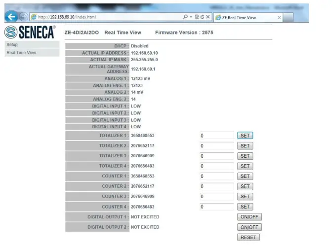
CONFIGURATION OF THE ZE MODULE WITH THE WEB SERVER
The web server can be used to configure the ZE module. To view all parameters, click on the ‘Setup’ button to the left of the screen:
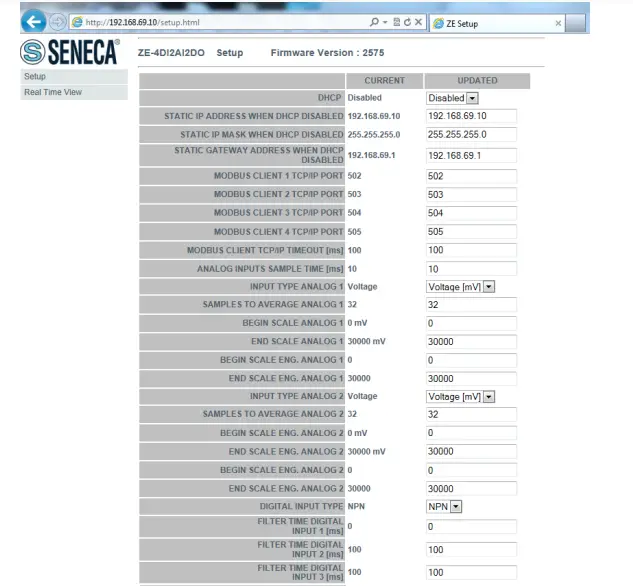
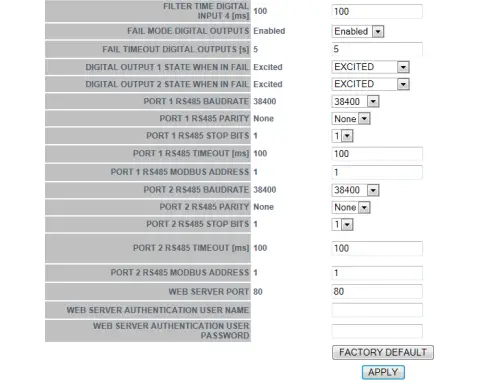
The first column represents the parameter name and the second column (current) is the value of the current parameter. The last column (updated) can be used to change the current configuration. Once the configuration has been made, you must confirm with ‘APPLY’ to make the new configuration operational.
ATTENTION!
ALWAYS REMEMBER TO CONFIGURE THE WEB SERVER AUTHENTICATION USERNAME AND PASSWORD TO RESTRICT ACCESS TO THE WEB SERVER. IF YOU LEAVE THE TWO PARAMETER TEXT BOXES BLANK, AUTHENTICATION WILL NOT BE REQUIRED TO ACCESS THE WEB SERVER. FOR SECURITY REASONS, AUTHENTICATION PARAMETERS CAN ONLY BE CHANGED VIA THE WEB SERVER.
REAL-TIME VALUES ON THE WEB SERVER
It is also possible to use the web server to display values in real time. The ‘Real Time view’ page can also be used to change values for totalisers, counters and outputs: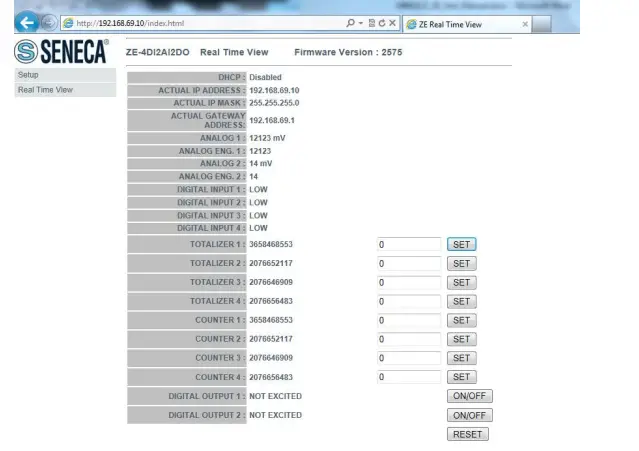
SOFTWARE EASY SETUP for Windows
(SOLO Z-4DI-2AI-2DO)
From the Quick Start menu, select the device model (you can also click on the tab and select the correct model from the button).
The ‘Easy ZE’ configuration software starts: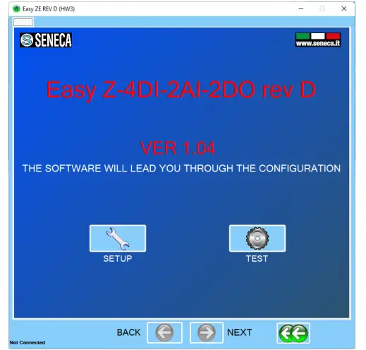
Click ‘AUTOMATIC SEARCH’ for automatic connection to the Z-4DI-2AI-2DO device. The software tries to connect with all serial ports until the device responds.
At this point, the configuration menu will be displayed: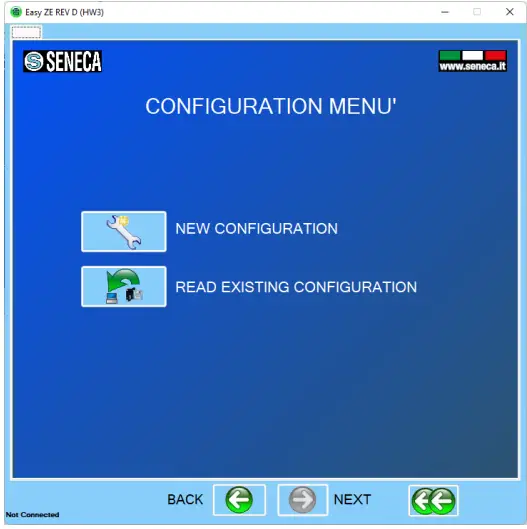
Firmware Update
Model Z-4DI-2AI-2DO
With a new Easy Setup revision, Seneca is able to include new firmware for the device. A new firmware update can include new features or bug fixes.
WARNING!
Once the firmware update has started, do not switch off the device before the procedure is complete. Switch on the ZE device and connect it to the PC
On the configuration menu, click on ‘Software update’.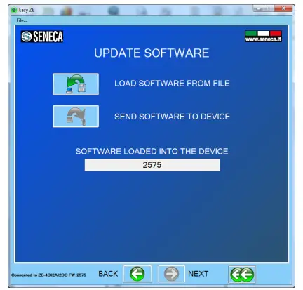 Press “Load software from file”: the software will directly open the firmware directory. If the “new software” revision is newer than the “software in the device” revision, click “Send software to the device”. The firmware update takes about 6 minutes.
Model ZE-4DI-2AI-2DO/ZE-2AI
To update devices use the webserver under ‘Firmware Update’.
ALL RIGHTS RESERVED. NO PART OF THIS PUBLICATION MAY BE REPRODUCED WITHOUT PRIOR PERMISSION.
www.seneca.it


