![]()
Information
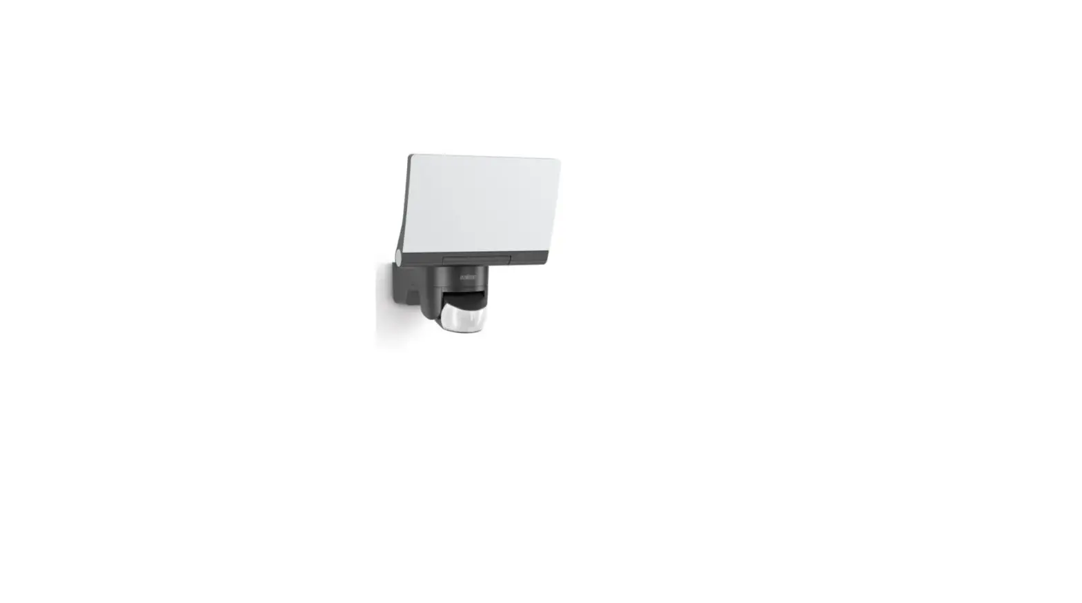
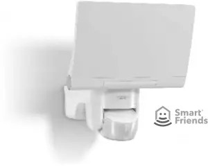
XLED home 2 Z-Wave
Follow written instructions!
3.2
3.7

- 3 –
– 5 –
5.3 5.5
5.6
– 7 –
1. About this document
Please read carefully and keep in a safe place.
- Under copyright. Reproduction either in whole or in part only with our consent.
- Subject to change in the interest of technical progress.
Symbols

Hazard warning!

Reference to other information in the document.
2. General safety precautions
Disconnect the power supply before attempting any work on the unit.
- Installing these units involves work on the mains voltage supply; installation must therefore be carried out professionally in accordance with the applicable national wiring regulations and electrical operating conditions. (
 -VDE 0100, -ÖVE/ÖNORM E 8001-1,
  -SEV 1000)
 - The light must be positioned so that it is not expected that anybody can stare into the light for any prolonged period from a distance of less than 0.3 m.
- The floodlight enclosure heats up when the light is on. Only adjust the angle of the LED panel once it has cooled down. Do not look into the LED light at short range or for any prolonged period (> 5 min). You could damage your retina.
- Do not install the unit on (normally) flammable surfaces.
3. XLED home 2 / XLED home 2 XL
Proper use
- Sensor-switched floodlight suitable for wall mounting outdoors.
- Fully swivelling LED panel and movable sensor.
Movement triggers lights, alarms and many other devices. With the fully swivelling panel, the floodlight can be used at home to provide perfect illumination for lighting up property, or commercially for lighting up business premises. In conjunction with the opal cover, this extremely efficient technology provides wide-area lighting.
This device can be integrated into the Smart Friends system or any other Z-Wave network. Z-Wave is a wireless standard for interconnecting Z-Wave devices. The sensor parameters of the sensor-switched LED floodlight can be used for wireless-based building automation. Besides certified Z-Wave controllers, it is recommended to use the Smart Friends Box. This smarthome control centre can be used for interconnecting Z-Wave products from STEINEL and the Smart Friends products from ABUS, Paulmann and Schellenberg.
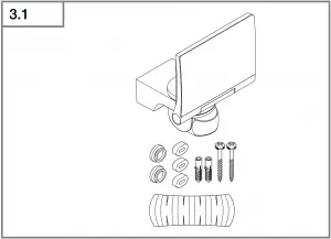
Package contents (Fig 3.1)
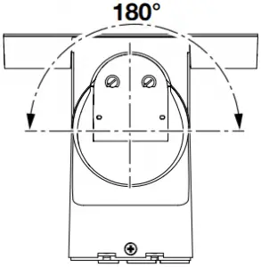
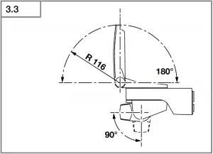
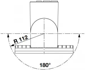
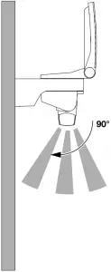
Sensor adjustment range (Fig 3.2 / 3.3 / 5.6)
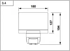
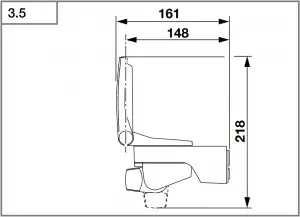
Product dimensions (Fig 3.4 / 3.5)
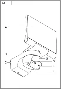
Product components (Fig 3.6)
A LED panel
B Enclosure
C Wall mount
D Sensor unit
E Twilight setting
F Z-Wave control dial
G Status LED
4. Electrical installation
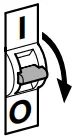
- Switch OFF power supply (Fig 3.7)
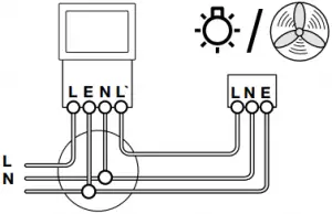
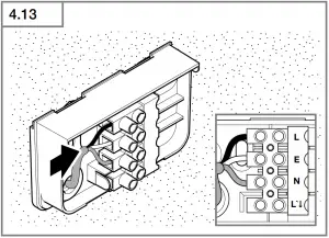
Connecting the mains power supply lead
The supply lead consist of three wires:
L = Phase conductor (usually black, brown or grey)
N = Neutral conductor (usually blue)
PE = Protective-earth conductor (green/yellow)
If you are in any doubt, identify the conductors using a voltage tester; then disconnect from the power supply again. Connect the phase conductor (L) and neutral conductor (N) to the terminal block. The protective-earth conductor can be looped through by means of terminal (E).
Wiring diagram (Fig 3.7)
Important: incorrectly wired connections will produce a short circuit later on in the product or your fuse box. In this case, you must identify the individual conductors once again and reconnect them.
The light source of this luminaire cannot be replaced. If the light source needs to be replaced (e.g. at the end of its service life), the complete luminaire must be replaced.
- 13 -
5. Mounting
- Check all components for damage.
- Do not use the product if it is damaged.
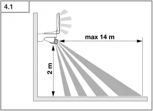
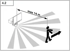
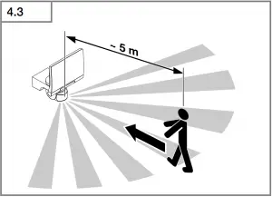
- Select an appropriate mounting location, taking the reach and motion detection into consideration. (Fig 4.1)
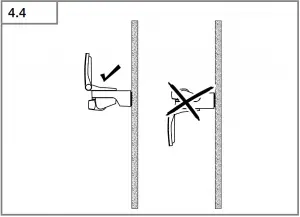
- Aiming the sensor-switched floodlight. (Fig 4.4)
The most reliable motion detection is achieved by mounting the unit to face across the direction in which people walk and by making sure no obstacles (e.g. trees, walls etc.) interrupt the line of sensor vision. (Fig 4.2 / 4.3)
Mounting procedure
- Switch OFF power supply. (Fig 3.7)
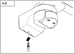
- Undo retaining screw. (Fig 4.5)
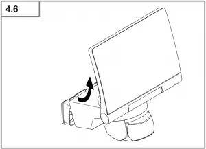
- Detach enclosure (B) from wall mount (C). (Fig 4.6)
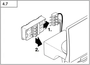
- Detach plug-in terminal (male) from wall mount. (Fig 4.7)
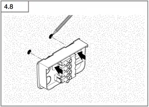
- Mark drill holes. (Fig 4.8)
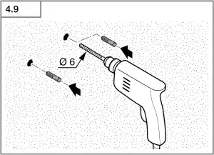
- Drill holes and fit wall plugs. (Fig 4.9)
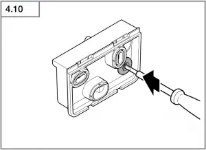
- Fit sealing plug. (Fig 4.10)
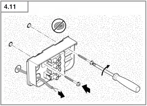
- Power supply lead, concealed (Fig 4.11)
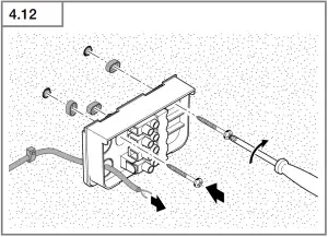
– Power supply lead, surface-mounted, with spacers (Fig 4.12) - Connect conductors. (Fig 4.13)
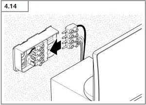
- Connect plug-in terminal. (Fig 4.14)
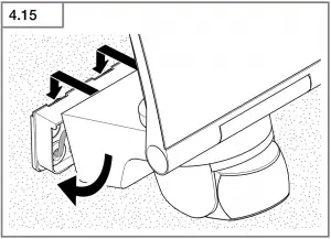
- Fit enclosure onto wall mount. (Fig 4.15)
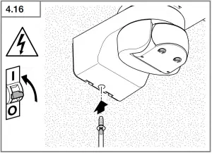
- Screw in retaining screw. (Fig 4.16)
- Switch ON power supply. (Fig 4.16)
- Make settings → “6. Function”
6. Function
The sensor-switched LED floodlight will also work without being integrated into a Z-Wave network. In this case, the time setting is permanently set to 3 minutes. When putting the floodlight into operation, it will switch OFF after the 10-second calibration phase and is then activated for sensor mode. The floodlight can now be integrated into the Z-Wave network.
The settings can be made via control dials or via Z-Wave network.
The settings last selected will always be in effect regardless of whether they were made via the control dials or via Z-Wave network.
Factory settings
Twilight level (E): 2000 lux
Time setting: 3 min
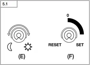
Twilight setting (Fig 5.1/E)
infinitely variable
Control dial set to ![]() = twilight operation approx. 2 lux
= twilight operation approx. 2 lux
Control dial set to ![]() = daylight operation approx. 2000 lux
= daylight operation approx. 2000 lux
Note: To adjust the detection zone in daylight, the control dial must be set to ![]() = daylight operation.
= daylight operation.
Reach setting/adjustment
The detection zone can be optimised to suit requirements.
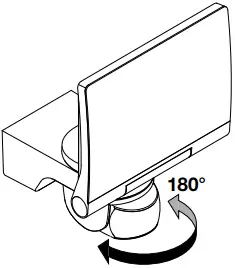
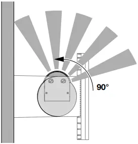
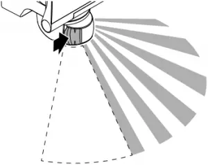
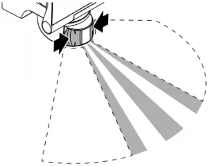
Sensor unit
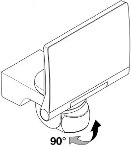
- Sensor unit swivels through 180°. (Fig 5.3)
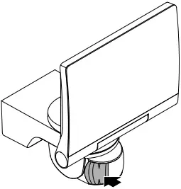
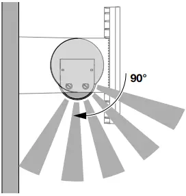
- Sensor unit tilts through 90°. (Fig 5.6)
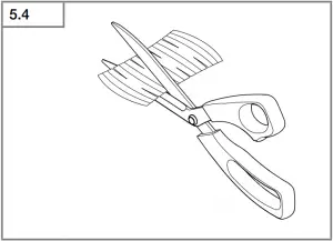
Adhesive shrouds (Fig 5.4)
The film shroud can be used for masking out any number of lens segments to limit reach as required. Inadvertent triggering is ruled out or the sensor can be targeted to watch over danger spots (Fig 5.5).
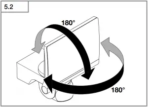
Other: Floodlight adjustment range
(Fig3.2 / 3.3 / 5.2)
7. Integration into Z-Wave networks
This product can be operated in any Z-Wave network with other Z-Wave certified devices from other manufacturers. All non-battery operated nodes within the network will act as repeaters regardless of vendor to increase reliability of the network.
| Inclusion | Add |
| Exclusion | Remove |
These instructions for including and excluding STEINEL Z-Wave products have been written for the Smart Friends system. They may not always apply to other Z-Wave products. You will find further details in the description of your Z-Wave controller. (To start the floodlight’s inclusion or exclusion mode, turn the device’s control dial (F) to “Set” and back to “0” within 5 seconds).
Following exclusion, all configuration parameters (time, sensitivity etc.) remain intact until next inclusion and the light now works in standalone mode as a result, Z-Wave can also be used for the light’s standalone setting.
- 14 -
Z-Wave control dial (F)
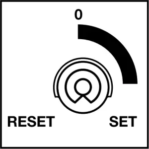
Control dial for inclusion and exclusion as well as for returning the device to the factory setting.
Adding XLED home 2 to the Smart Friends system:
1 Download the Smart Friends app from the app store.


2 In the rooms view, activate the edit mode.
3 Select the chosen room and press the “Add device” button.
4 To put the device into inclusion mode, turn the device’s control dial (F) to “Set” and back to “0” within 5 seconds. The status LED (G) lights up to show that this mode is selected.
5 The app displays a confirmation message once inclusion has been successfully completed.
Removing XLED home 2 from the Smart Friends system:
1 In the rooms view, activate the edit mode.
2. Select the device in the chosen room and press the “delete” ![]() button. Press delete and follow the instructions in the app.
button. Press delete and follow the instructions in the app.
3 To put the device into exclusion mode, turn the device’s control dial (F) to “Set” and back to “0” within 5 seconds. The red status LED (G) lights up to show that this mode is selected.
4 The app displays a confirmation message once exclusion has been successfully completed.
Setting XLED home 2 with the app:
- After programming, an ON/OFF scene is automatically created in the app.
- The following setting values are then automatically stored:
a) Twilight setting = control-dial setting
b) Time setting = 3 min switch-OFF delay
- The twilight and time settings can be selected to the accuracy of one lux and one second respectively in the “Scene” menu.
Resetting XLED home 2 to the factory settings:
Please only perform these steps if the main network controller is missing or not working for other reasons.
1 Turn the device’s control dial (F) to “Set” and move it to “Reset” within 5 seconds.
2 The status LED (G) briefly flashes to show that the light has been reset.
3 The device is now no longer included in the Z-Wave system and has been returned to factory settings.
Note: the current firmware version for the light is available for downloading from z-wave.steinel.de.
8. Operation/maintenance
The unit is not suitable for burglar alarm systems as it is not tamperproof in the manner prescribed for such systems. Weather can affect the operation of the sensor-switched LED floodlight. Strong gusts of wind, snow, rain and hail may cause the light to come ON when it is not wanted because the sensor is unable to distinguish between sudden changes in temperature and sources of heat. The detector lens may be cleaned with a damp cloth if it gets dirty (do not use cleaning agents).
9. EC Declaration of Conformity
STEINEL Vertrieb GmbH hereby declares that the XLED home 2 Z-Wave radio equipment type conforms to Directive 2014/53/EU. The full wording of the EU Declaration of Conformity is available for downloading from the following Internet address: http://www.steinel.de
10. Warranty
This STEINEL product has been manufactured with utmost care, tested for proper operation and safety and then subjected to random sample inspection. Steinel guarantees that it is in perfect condition and proper working order. The warranty period is 5 years and starts on the date of sale to the consumer. We will remedy defects caused by material flaws or manufacturing faults. The warranty will be met by repair or replacement of defective parts at our own discretion.
- 15 -
The warranty shall not cover damage to wear parts, damage or defects caused by improper treatment or maintenance. Further consequential damage to other objects shall be excluded.
Claims under the warranty will only be accepted if the unit is sent fully assembled and well-packed with a brief description of the fault, a receipt or invoice (date of purchase and dealer’s stamp) to the appropriate Service Centre.
Service
Our Customer Service Department will repair faults not covered by the warranty or after the warranty period has expired. Please send the product well packed to your nearest Service Centre.

11. Technical specifications
| Dimensions (H × W × D) | 194 × 180 × 161 | |
| Output | 14.8 W / 80 lm/W | |
| Luminous flux / brightness | 1184 lm | |
| Weight | 0.575 kg | |
| Area illuminated | Front view 283.1 cm2 | Side view 113 cm2 |
| Mains current | 75 mA | |
| Power factor | max. 100 W (resistive load, e.g. light bulbs) max. 500 W (uncorrected, inductive, cos φ = 0.5, e.g. fluorescent lamps) max. 4 × 56 W, C ≤ 88 μF | |
| Efficiency | 80 lm/W | |
| Colour temperature | 4000K (neutral white) | |
| Colour rendering index | Ra ≥ 80 | |
| Supply voltage | 230-240 ~V / 50/60 Hz | |
| Sensor system | Passive infrared | |
| Reach | max. 14 m via control dial | |
| Angle of coverage | 140° | |
| Time setting | 3 min factory setting / 1 s to 15 min with the app | |
| Twilight setting | 2-2000 lux via control dial and with the app | |
| IP / protection class | IP44 / II | |
| Z-Wave wireless range | approx. 100 m (unobstructed line of vision) | |
| Radio frequency band | 868 MHz | |
| Transmitter power | ≤ 2.5 mW | |
- 16 -
12. Troubleshooting
| Malfunction | Cause | Remedy |
| Sensor-switched LED floodlight without power | • Fuse faulty; not switched ON; break in wiring • Short-circuit | • New fuse, turn on power switch, check wiring with voltage tester • Check connections |
| Sensor-switched LED floodlight will not switch ON | • Twilight setting in night-time mode during daytime operation • Mains switch OFF • Fuse faulty • Detection zone not correctly adjusted | • Reset • Switch ON • Replace fuse, check connection if necessary • Readjust |
| Sensor-switched LED floodlight will not switch OFF | • Continued movement within the detection zone | • Check zone and readjust if necessary or apply shroud |
| Sensor-switched LED floodlight keeps switching ON and OFF | • Animals moving in detection zone | • Tilt sensor higher or apply specific shrouds; adjust detection zone or fit shrouds |
| Sensor-switched LED floodlight switches ON when it should not | • Wind is moving trees and bushes in the detection zone • Cars in the street are detected • Sudden temperature changes due to weather (wind, rain, snow) or exhaust air from fans or open windows • Sensor-switched LED floodlight swaying (moving), resulting, for example, from gusts of wind or heavy precipitation | • Change detection zone • Change detection zone • Adjust detection zone or install in a different place • Fit sensor-switched LED floodlight to a firm surface |
| The device cannot be added (and is not yet added) | • Z-Wave controller too far from the device | • Reduce distance from Z-Wave controller • Install a Z-Wave repeater |
| The device cannot be added | • It is already added | • Remove device from existing network • Carry out default reset |
| Status-LED (G) flashing for 1 second every 5 seconds | • No wireless contact with the Smart Friends Box or other Z-Wave controller | • Re-start Smart Friends Box or Z-Wave controller • Reduce distance from Z-Wave controller • Install a Z-Wave repeater |
| Status LED (G) flashing rapidly all the time | • Critical fault | • Briefly disconnect device from the mains power supply |
- 17 -
Advanced Configuration
For more detailed information, please download the professional instructions from z-wave.steinel.de.
A. Description of device endpoints:
The functionality of the device is divided to endpoints by their using.
0 = ROOT
To root summarizes whole device function, to root endpoint is mapped all functionality from the endpoint 1 and most of the endpoints 2 and 3.
Device type = On/Off Power Switch
Supported Command Classes:
COMMAND_CLASS_ZWAVEPLUS_INFO ( v2 )
COMMAND_CLASS_BASIC ( v1 )
COMMAND_CLASS_VERSION ( v2 )
COMMAND_CLASS_FIRMWARE_UPDATE_MD ( v3 )
COMMAND_CLASS_MANUFACTURER_SPECIFIC ( v1 )
COMMAND_CLASS_MULTI_CHANNEL ( v4 )
COMMAND_CLASS_DEVICE_RESET_LOCALLY ( v1 )
COMMAND_CLASS_CONFIGURATION ( v1 )
COMMAND_CLASS_POWERLEVEL ( v1 )
COMMAND_CLASS_NODE_NAMING ( v1 )
COMMAND_CLASS_NOTIFICATION ( v4 )
COMMAND_CLASS_ASSOCIATION ( v2 )
COMMAND_CLASS_MULTI_CHANNEL_ASSOCIATION ( v3 )
COMMAND_CLASS_ASSOCIATION_GRP_INFO ( v1 )
COMMAND_CLASS_SWITCH_BINARY ( v1 )
COMMAND_CLASS_SCENE_ACTIVATION ( v1 )
COMMAND_CLASS_SCENE_ACTUATOR_CONF ( v1 )
COMMAND_CLASS_SWITCH_ALL ( v1 )
COMMAND_CLASS_APPLICATION_STATUS ( v1 )
COMMAND_CLASS_SENSOR_MULTILEVEL ( v4 )
Controlled Command Classes:
COMMAND_CLASS_BASIC ( v1 )
1 = LAMP
To endpoint 1 is mapped basic lamp functionality.
Device type = On/Off Power Switch
Supported Command Classes:
COMMAND_CLASS_ZWAVEPLUS_INFO ( v2 )
COMMAND_CLASS_BASIC ( v1 )
COMMAND_CLASS_ASSOCIATION ( v2 )
COMMAND_CLASS_MULTI_CHANNEL_ASSOCIATION ( v3 )
COMMAND_CLASS_ASSOCIATION_GRP_INFO ( v1 )
COMMAND_CLASS_SWITCH_BINARY ( v1 )
COMMAND_CLASS_SCENE_ACTIVATION ( v1 )
COMMAND_CLASS_SCENE_ACTUATOR_CONF ( v1 )
COMMAND_CLASS_SWITCH_ALL ( v1 )
COMMAND_CLASS_APPLICATION_STATUS ( v1 )
Controlled Command Classes:
No
2 = MOTION SENSOR
To endpoint 2 is mapped motion sensor (PIR) functionality.
Device type = Sensor – Notification
Supported Command Classes:
COMMAND_CLASS_ZWAVEPLUS_INFO (v2)
COMMAND_CLASS_BASIC (v1)
COMMAND_CLASS_ASSOCIATION (v2)
COMMAND_CLASS_NOTIFICATION (v4)
COMMAND_CLASS_MULTI_CHANNEL_ASSOCIATION (v3)
COMMAND_CLASS_ASSOCIATION_GRP_INFO (v1)
Controlled Command Classes:
COMMAND_CLASS_BASIC (v1)
Special meaning of BASIC CC:
Basic Set: active ( 0xFF ) / inactive ( 0x00 ) sensor function
Basic Get: get sensor activity
Basic Report: sensor activity status
3 = AMBIENT LIGHT SENSOR
To endpoint 3 is mapped ambient light sensor ( luminescence sensor synchronized with lamp ) functionality.
Device type = Sensor – Multilevel
Supported Command Classes:
COMMAND_CLASS_ZWAVEPLUS_INFO (v2)
COMMAND_CLASS_SENSOR_MULTILEVEL (v4)
COMMAND_CLASS_ASSOCIATION (v2)
COMMAND_CLASS_MULTI_CHANNEL_ASSOCIATION (v3)
COMMAND_CLASS_ASSOCIATION_GRP_INFO (v1)
Controlled Command Classes:
No
B. Description of association groups:
0 = ROOT DEVICE
Group 1 - “Lifeline” - only 1 node
Lifeline messages
– Device Reset Locally
– Notifications:
0x09 ( System ) - Hardware failure with manufacturer proprietary code ( 0x03 )
0x09 ( System ) - Software failure with manufacturer proprietary code ( 0x04 )
0x07 ( Home security ) - Motion Begin event ( 0x08 )
0x07 ( Home security ) - Motion End event ( 0x00, 0x08 )
– Binary Switch Report - lamp state
– Multilevel Sensor Report – value of internal ambient light sensor
Motion Begin and Motion End events are sent along with frames to group 3. If multichannel association is created the events are sent from motion sensor endpoint.
Switch Report is sent immediately upon a change of status along with frames to group 2. If multichannel association is created the events are sent from lamp endpoint.
Multilevel Sensor Report is sent a maximum of once per 1 minute (if the value has changed by least by 3%) and a minimum of once per 15 minutes (if the value has not changed). If the ambient light value is old (cannot measure because of permanent light), the value is not transmitted via lifeline. Multilevel Sensor Report can be also added to some other events to send in bulk. If multichannel association is created the events are sent from light sensor endpoint. All notifications to lifeline are sent as sensor states regardless of sensor settings and states as SLAVE_MODE, LOCAL_DISABLED and MOTION_ENABLE.
Group 2 - “On/Off control” - max 16 nodes
Group 2 is used for directly controlling Z-Wave devices via BASIC SET commands through the evaluation of movement and light as with internal use (so that all of these devices work together). This is intended for use especially with third-party devices that do not implement reactions for motion events. BASIC_SET and similar Z-Wave commands are not retransmitted intentionally to slaves and must be sent to slave devices via the controlling device simultaneously. Only for use in master-slave system, multidevice control is not possible.
– 18 –
Group 2 is evaluated and frames are transmitted there also in SLAVE_MODE, regardless of LOCAL_DISABLED state and when MOTION_ENABLE is off (not using internal motion sensor just reacts for remote motion events then). If multichannel association is created the events are send from motion sensor endpoint.
Group 3 - “Notification Report” - max 16 nodes
Group 3 sends MOTION_BEGIN and MOTION_END frames.
MOTION_BEGIN frame = Notification 0x07 (Home security) - Motion detection without location (0x08)
MOTION_END frame = Notification 0x07 (Home security) - After first motion detection MOTION_BEGIN is sent. If continual movement is detected MOTION_BEGIN is sent every 1 minute repeatedly. When motion ends, MOTION_END is sent 5 seconds after the last motion detection. Notification to group 3 is sent only when NIGHT_MODE = ON and MOTION_ENABLE = ON, regardless of LOCAL_DISABLE state.
All devices in a group should have the same TIME settings in order that they switch off at the same time.
If multichannel association is created the events are send from motion sensor endpoint.
Group 4 - “Ambient light” - max 16 nodes
Ambient Light via group 4 is intended to substitute locally measured LUX values in target devices - so that the network can have one source of ambient light value. The frame rate is a value being sent a maximum of once per 2.5 minutes, and a minimum of once per 15 minutes.
When device already uses remote Ambient light value, then this value is also retransmitted to group 4.
All devices in such a group should have the same LIGHT (threshold) settings in order that night mode is detected at the same time.
If multichannel association is created the events are send from light sensor endpoint.
1 = LAMP
The lifeline messages are sent via Root lifeline if not used multichannel association.
2 = MOTION SENSOR
The lifeline messages are sent via Root lifeline if not used multichannel association.
Group 2 - its mirror of group 2 of root
Group 3 - its mirror of group 3 of root
3 = AMBIENT LIGHT SENSOR
The lifeline messages are sent via Root lifeline if not used multichannel association.
Group 2 - its mirror of group 4 of root
C. Configuration description:
Time [ s ]:
| Parameter Number | Size | Range | Default |
| 1 (TIME) | 2 | 5-900 | 180 |
Duration of light after motion detection.
Light threshold [ lx ]:
| Parameter Number | Size | Range | Default |
| 2 (LIGHT) | 2 | 2-2000, 0 | 2000/poti state |
0 - run Learn ambient light sequence.
2000 – is used as daylight (always night mode).
Value can be controlled via potentiometer - potentiometer value is used as the default value and any potentiometer movement rewrites the current setting.
Motion Sensor (PIR) Sensitivity [%]:
| Parameter Number | Size | Range | Default |
| 5 (SENSITIVITY) | 1 | 2-100 | 100 |
Value can be controlled via potentiometer - potentiometer value is used as the default value and any potentiometer movement rewrites the current setting.
Brightness measuring interval [ minutes ]:
| Parameter Number | Size | Range | Default |
| 6 (BRIGHTNES MEAS INTERVAL) | 1 | 5-120, 0 | 0 |
Interval for ambient light measuring when lamp is on (lamp switches off shortly and measures). 0=function is off.
Use External Ambient Light Value:
| Parameter Number | Size | Range | Default |
| 8 (GLOBAL_LIGHT) | 1 | 0/1 | 1 |
When GLOBAL_LIGHT mode is ON - device overrides its own light sensor values and uses Light report values from any Z-Wave light sensor instead - this has to be configured appropriately to send light automatically.
If the last remote light level value is older than 30 minutes, the internal light value is used again until the next external value is received.
Disable local control:
| Parameter Number | Size | Range | Default |
| 9 (SLAVE_MODE) | 1 | 0-4 | 2 |
Bit Field:
Bit | 7 | 6 | 5 | 4 | 3 | 2 | 1 | 0 |
| function | – | – | – | – | – | “Stupid” mode | Central unit checking in slave mode | Slave mode |
“Stupid” mode (bit 2 = 1):
– has higher priority then slave mode.
– lamp is permanently on ( usefull for simple power wall switch controlling ).
Slave mode (bit 0 = 1):
– only if included in Z-Wave network
– usefull for controlling via third-party sensor
– lamp is directly controlled via Z-Wave, internal sensors are not used for controlling it.
Central unit checking (bit 1 = 1):
(usefull especialy for controlling via gateway)
When Slave bit is 0:
– lamp signalises fail of lifeline connection (if this bit is zero fail of lifeline connection is not signalised)
When slave bit is 1:
– lamp checks presence of Z-Wave device in lifeline group (gateway). If it is not present for 2 minutes (testing repeatedly every 30 seconds) device switches to normal mode in the same way as after the end of local disabled mode (ON_BEHAVIOUR)
– The device checks every 1 minute for recovery of Lifeline connection.
– if no lifeline specified – it works in normal mode
– 19 –
Be careful with this option, lamp stops using it’s own motion sensor in Slave and Stupid mode.
Off behavior (timeout):
| Parameter Number | Size | Range | Default |
| 10 (OFF_BEHAVIOUR) | 2 | 0 – 209,255 | 10 |
Behaviour after BASIC OFF (and similar commands).
If a transition (even with zero change) with a non-default duration is to be processed, the transition cannot be interrupted by any motion event in any case.
| 0 | Lamp is switched off and remains so until any new motion event (local or remote) is received. |
| 1 – 209 | Lamp is switched off and remains so until after a specified timeout once a new motion event (local or remote) is received. Timeout: 1..100 – 1 second (1) to 100 seconds (100) in 1-second resolution 101..200 – 1 minute (101) to 100 minutes (200) 1-minute resolution 201..209 – 1 hour (201) to 9 hours (209) in 1-hour resolution |
| 210 – 254 | Reserved |
| 255 | Lamp is switched off for TIME (cfg 1). It does not wait for a motion event and works normally via current motion evaluation. |
On behaviour (timeout):
| Parameter Number | Size | Range | Default |
| 11 (ON_BEHAVIOUR) | 2 | 0 – 209, 255 | 255 |
Behaviour after BASIC ON (and similar commands).
If a transition (even with zero change) with a non-default duration is to be processed, the transition cannot be interrupted by any motion event in any case.
| 0 | Lamp is switched on and remains so until any new motion event (local or remote) is received. It then works normally via current motion evaluation. Notice – during the day, this mode cannot be ended remotely due to motion events not being transmitted – only via local motion sensor if enabled. |
| 1 – 209 | Lamp is switched on and remains so until after a specified timeout once a new motion event (local or remote) is received. It then works normally via current motion evaluation. Timeout: 1..100 – 1 second (1) to 100 seconds (100) in 1-second resolution 101..200 – 1 minute (101) to 100 minutes (200) in 1-minute resolution 201..209 – 1 hour (201) to 9 hours (209) in 1-hour resolution Notice – during the day, this mode cannot be ended remotely due to motion events not being transmitted – only via local motion sensor if enabled. |
| 210 – 254 | Reserve |
| 255 | Lamp is switched on for TIME (cfg 1). It does not wait for a motion event and works normally via current motion evaluation. |
On behavior time over (timeout):
| Parameter Number | Size | Range | Default |
| 12 (ON_TIME_OVER) | 2 | 0 – 209, 255 | 204 |
Time limit to stop waiting for motion after timeout of ON_BEHAVIOUR or OFF_ON_BEHAVIOUR (0-209) to prevent staying ON forever when is no motion.
| 0 | Stop waiting just after timeout. |
| 1 – 209 | 1..100 – 1 second (1) to 100 seconds (100) in 1-second resolution 101..200 – 1 minute (101) to 100 minutes (200) in 1-minute resolution 201..209 – 1 hour (201) to 9 hours (209) in 1-hour resolution |
| 210 – 254 | Reserve |
| 255 | Never stop waiting before motion. |
Sequence Off-On behavior (timeout):
| Parameter Number | Size | Range | Default |
| 14 (OFF_ON_ BEHAVIOUR) | 2 | 0 – 209, 255 | 204 |
Behaviour after after a rapid sequence of BASIC OFF and BASIC ON commands.
The intention is to use a much longer timeout value than the time after a single OFF command which should then be followed by a short timeout value.
The behaviour is the same as for parameter 11 (ON_LOCAL_DISABLE) butexcept: 255 device ignores OFF – ON sequence and uses ON behaviour.
Sequency timing:
| Parameter Number | Size | Range | Default |
| 15 (SEQUENCY_TIME) | 1 | 10 – 50 | 10 |
Time in [100 miliseconds] of maximum delay between BASIC ON and BASIC OFF (and vice versa) to consider this as a sequence. It is typically 1 second, but can be exceptionally longer due to retransmissions and overload - In this case, a longer interval can be allowed (up to 5 seconds).
Motion Off behaviour (timeout):
| Parameter Number | Size | Range | Default |
| 16 (MOTION_DISABLE) | 2 | 0 – 209, 255 | 0 |
Motion disable timeout after BASIC SET to motion endpoint when the internal motion sensor is not used for evaluating the behaviour of the lamp and groups 2 and 3. Events are, however, still transmitted to the Lifeline, and the lamp can be controlled via remote motion sensors.
| 0 | BASIC SET to Motion endpoint ignored, Motion sensor still enabled |
| 1 – 209 | Internal motion sensor is disabled for specified timeout after BASIC SET 0x00 to Motion endpoint. Timeout: 1..100 – 1 second (1) to 100 seconds (100) in 1-second resolution 101..200 – 1 minute (101) to 100 minutes (200) in 1-minute resolution 201..209 – 1 hour (201) to 9 hours (209) in 1-hour resolution |
| 210 – 254 | Reserve |
| 255 | BASIC SET to Motion endpoint ignored, Motion sensor still disabled |
– 20 –
D STEINEL Vertrieb GmbH
Dieselstraße 80-84
33442 Herzebrock-Clarholz
Tel: +49/5245/448-188
Fax: +49/5245/448-197
www.steinel.de
A Steinel Austria GmbH
Hirschstettner Strasse 19/A/2/2
A-1220 Wien
Tel.: +43/1/2023470
Fax: +43/1/2020189
[email protected]
CH PUAG AG
Oberebenestrasse 51
CH-5620 Bremgarten
Tel.: +41/56/6488888
Fax: +41/56/6488880
[email protected]
GB STEINEL U.K. LTD.
25, Manasty Road · Axis Park
Orton Southgate
GB-Peterborough Cambs PE2 6UP
Tel.: +44/1733/366-00
Fax: +44/1733/366-701
[email protected]
F STEINEL FRANCE SAS
ACTICENTRE – CRT 2
Rue des Famards – Bât. M – Lot 3
F-59818 Lesquin Cedex
Tél.: +33/3/20 30 34 00
Fax: +33/3/20 30 34 20
[email protected]
NL Van Spijk B.V.
Postbus 2
5688 HP OIRSCHOT
De Scheper 402
5688 HP OIRSCHOT
Tel. +31 499 571810
Fax. +31 499 575795
[email protected]
www.vanspijk.nl
B VSA Belgium
Hagelberg 29
B-2440 Geel
Tel.: +32/14/256050
Fax: +32/14/256059
[email protected]
www.vsabelgium.be
I STEINEL Italia S.r.l.
Largo Donegani 2
I-20121 Milano
Tel.: +39/02/96457231
Fax: +39/02/96459295
[email protected]
www.steinel.it
110050436 03/2017_J Technische Änderungen vorbehalten. / Subject to technical modification without notice.


