![]()
 Nice
Nice
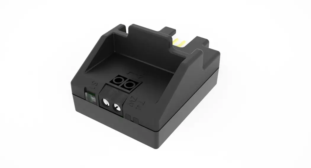
IBT4ZWAVE
BusT4 – Z-Wave interface
Instructions and warnings for installation and use
WARNINGS AND GENERAL PRECAUTIONS
- CAUTION! – This manual contains important instructions and warnings for personal safety. Carefully read all parts of this manual. If in doubt, suspend installation immediately and contact Nice Technical Assistance.
- CAUTION! – Important instructions: keep this manual in a safe place to enable future product maintenance and disposal procedures.
- CAUTION! – All installation and connection operations must be performed exclusively by suitably qualified and skilled personnel with the unit disconnected from the mains power supply.
- Important! – If the BUS T4 connection is used for the IBT4N interface, the IBT4ZWAVE cannot be connected to the control unit.
- This product may only be used indoors or protected from weather conditions by the control unit’s housing.
- The product’s packaging materials must be disposed of in full compliance with local regulations.
- Do not open the device protection housing as it contains non-serviceable electrical circuits.
- Never apply modifications to any part of the device. Operations other than those specified may only cause malfunctions. The manufacturer declines all liability for damage caused by makeshift modifications to the product.
- Never place the device near sources of heat and never expose to naked flames. These actions may damage the product and cause
malfunctions. - This product is not intended for use by people (including children) with reduced physical, sensory or mental capabilities or who lack experience and knowledge unless they have been given supervision or instruction concerning the use of the product by a person responsible for their safety.
- Make sure that children do not play with the product.
- Check the warnings in the instruction manual for the motor that the product is connected to.
- Handle the product with care, being sure not to crush, knock or drop it in order to avoid damage.
PRODUCT DESCRIPTION
CAUTION! – Any use other than that specified herein or in environmental conditions other than those stated in this manual is to be considered improper and is strictly forbidden!
The IBT4ZWAVE accessory is a device that – by means of Z-Wave™ communication – allows for controlling the movement and status of Gate&Door-type Nice automations compatible with the BUS T4 (Opera) protocol.
Before proceeding with the product’s installation, make sure to have the following:
- 1 Nice automation control unit of the Gate&Door catalog equipped with BUS T4 connector
- 1 Z-Wave smart home controller
- If you want to improve the IBT4ZWAVE Z-Wave range: 1 antenna compliant with the technical specification (see chapter 10) – not included.
INSTALLATION
| 1 | Disconnect the power supply from the automation’s control unit | 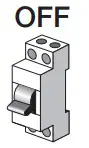 |
| 2 | All LEDs on the automation’s control unit should be off before continuing | |
| 3 | If you want to install the external antenna, you can do it now | 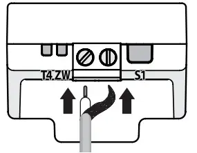 |
| 4 | If present, remove the plastic pre-cut element from the BUS T4 connector and check that there are no burrs | 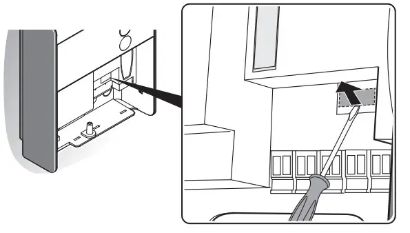 |
| 5 | Insert the IBT4ZWAVE into the BUS T4 port of the connector unit | 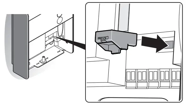 |
| 6 | Power the automation’s control unit |  |
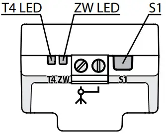
| 7 | LEDs on the IBT4ZWAVE will show adding and antenna status (Table 1) | |
| 8 | Wait for the IBT4ZWAVE to finish the initialization sequence (T4 LED flashing green) | |
| 9 | Add the device to the Z-Wave network; for the relevant procedure see Chapter 4 |
ADDING TO THE Z-WAVE NETWORK
![]() Install the external antenna before powering the device and adding to the Z-Wave network for the device to automatically
Install the external antenna before powering the device and adding to the Z-Wave network for the device to automatically
detect and enable it (use only antennas and cables compliant with technical specification – see chapter 10).
Adding manually
| 1 | Set the Z-Wave gateway into adding mode (see the Z-Wave gateway’s manual) | |
| 2 | On the IBT4ZWAVE press and release the S1 button 3 times | 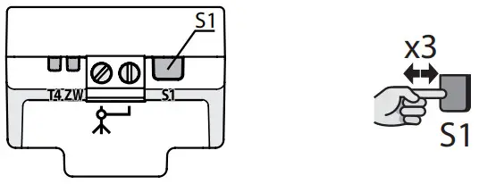 |
| 3 | LEDs on the IBT4ZWAVE will start slow flashing alternately | |
| 4 | If you are adding in Security S2 Authenticated, input the underlined part of the DSK (label on the box) | DSK: XXXXX-XXXXX-XXXXX-XXXXX XXXXX-XXXXX-XXXXX-XXXXX |
| 5 | When the adding process ends, the LEDs on the IBT4ZWAVE will show adding and antenna status (Table 1) |
Adding using SmartStart
SmartStart enabled products can be added into a Z-Wave network by scanning the Z-Wave QR Code present on the product with a controller providing SmartStart inclusion. SmartStart product will be added automatically within 10 minutes of being switched on in the network range.
| 1 | To use SmartStart your Z-Wave gateway needs to support Security S2 (see the Z-Wave gateway’s manual) | |
| 2 | Disconnect the power supply from the automation’s control unit | |
| 3 | Enter the full DSK string code to your Z-Wave gateway. If your controller is capable of QR scanning, scan the QR code placed on the label on the device and bottom of the box | |
| 4 | Power the automation’s control unit | |
| 5 | LEDs on the IBT4ZWAVE will start slow flashing alternately | |
| 6 | When the adding process ends, the LEDs on the IBT4ZWAVE will show adding and antenna status (Table 1) |
REMOVING FROM THE Z-WAVE NETWORK
| 1 | Set the Z-Wave gateway into remove mode (see the Z-Wave gateway’s manual) | |
| 2 | On the IBT4ZWAVE press and release the S1 button 3 times | |
| 3 | LEDs on the IBT4ZWAVE will start slow flashing alternately | |
| 4 | Wait for the removing process to end |
EXTERNAL ANTENNA
The IBT4ZWAVE is equipped with an internal antenna, but an external antenna can be connected to improve the Z-Wave network range, e.g. when the gate is far away from the house.![]() Check the technical specification to buy the correct antenna and cable (see chapter 10)!
Check the technical specification to buy the correct antenna and cable (see chapter 10)!
Checking and switching enabled antenna
The external antenna will be detected and enabled automatically after powering the device (if not added to the Z-Wave network), but you can switch manually between antennas using the following procedure.
| 1 | Press and hold the S1 button |  |
| 2 | Wait 3 seconds | |
| 3 | LEDs will show adding and antenna status (Table 1) for 3 seconds | |
| 4 | LEDs will turn off for 3 seconds | |
| 5 | When LEDs show the selected antenna, release the button: ZW LED (blue) for internal antenna, T4 LED (green) for external antenna (Table 2) |  |
| 6 | If you want to switch the antenna, press and release the S1 button |  |
| 7 | If the antenna was switched, the corresponding LED will flash 2 times: ZW LED (blue) for internal antenna, T4 LED (green) for external antenna (Table 2) |  |
OPERATION
To control the movement use the Z-Wave gateway’s interface or click the S1 button (works in Step-by-Step mode).
RESET
Reset procedure allows restoring the device back to its factory settings, which means all information about the Z-Wave gateway and user
the configuration will be deleted.
Resetting the device is not the recommended way of removing the device from the Z-Wave network. Use reset procedure only if the primary controller is missing or inoperable. Certain device removal can be achieved by the procedure of removing described.
| 1 | Press and hold the S1 button | |
| 2 | Wait 3 seconds | |
| 3 | LEDs will show adding and antenna status (Table 1) for 3 seconds | |
| 4 | LEDs will turn off for 3 seconds | |
| 5 | LEDs will show the selected antenna (Table 2) for 3 seconds | |
| 6 | When both LEDs light up simultaneously, release the button | 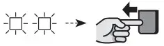 |
| 7 | Press and release the S1 button | |
| 8 | Both LEDs will flash once at the end of the procedure |  |
LED SIGNALS
Table 1 – LEDs Z-Wave and antenna status | |||
| T4 LED (green) | ZW LED (blue) | Z-Wave adding status | External antenna |
| OFF | ON for 3 seconds | Not added | Not connected |
| OFF | 2 flashes | Added (non-secure, SO, S2 Unauthenticated) | Not connected |
| OFF | 4 flashes | Added successful (Security S2 Authenticated) | Not connected |
| ON | ON for 3 seconds | Not added | Connected |
| ON | 2 flashes | Added (non-secure, SO, S2 Unauthenticated) | Connected |
| ON | 4 flashes | Added successful (Security S2 Authenticated) | Connected |
Table 2 – LEDs selected antenna | ||
| T4 LED (green) | ZW LED (blue) | Selected antenna |
| OFF for 3 seconds | ON for 3 seconds | Internal |
| ON for 3 seconds | OFF for 3 seconds | External |
TECHNICAL SPECIFICATIONS
The product IBT4ZWAVE is produced by Nice S.p.a. (TV). Warnings: – All technical specifications stated in this section refer to an ambient temperature of 20°C (± 5°C) – Nice S.p.a. reserves the right to apply modifications to the product at any time when deemed necessary, while maintaining the same functionalities and intended use.
| I BT4ZWAVE | |
| Type | control using Z-Wave network of devices fitted with a connector compatible with BUS T4 |
| Technology adopted | half-duplex 19200 Bps serial connection on differential bus |
| Power supply | 24V DC supplied by the control unit to which the IBT4ZWAVE is connected |
| Absorbed current | max 50 mA |
| Radio frequencies | 868.0-868.6; 869.7-870.0 MHz |
| Internal antenna max. transmit power | 10 dBm |
| External antenna center frequency | 868 MHz |
| External antenna max. peak gain | 3 dBi |
| External antenna max. transmit power | 13 dBm |
| External antenna cable length | 1 – 3 m |
| Antenna connector screws rated torque | 0.4 Nm |
| Casing protection rating | IP 40 (use indoors or in protected environments only) |
| Operating temperature | – 20 °C + +50 °C |
| Dimensions (mm) | 37 x 28 x h 21 |
| Weight | lOg |
Z-WAVE SPECIFICATION
The device is a Security Enabled Z-Wave Plus™ product and a Security Enabled Z-Wave gateway must be used in order to fully
utilize the product.
The device may be used with all devices certified with the Z-Wave Plus certificate and should be compatible with such devices produced by other manufacturers.
The device works as a Z-Wave signal repeater (all non-battery-operated devices within the network will act as repeaters to increase the reliability of the network).
Generic Device Type: GENERIC_TYPE_SWITCH_MULTILEVEL (0x11)
Specific Device Type: Not Used
Table 3 – Supported Command Classes | ||
| Command Class | Version | Secure |
| COMMAND_CLASS_ZWAVEPLUS _INFO [0x5E] | V2 | |
| COMMAND_CLASS_MULTILEVEL_SWITCH [0x26] | V4 | YES |
| COMMAND_CLASS_ASSOCIATION [0x85] | V2 | YES |
| COMMAND_CLASS_MULTI_CHANNEL_ASSOCIATION [0x8E] | V3 | YES |
| COMMAND_CLASS_ASSOCIATION_GRP _INFO [0x59] | V3 | YES |
| COMMAND_CLASS_DEVICE_RESET_LOCALLY [0x5A] | V1 | YES |
| COMMAND_CLASS_FIRMWARE_UPDATE_MD [0x7A] | V5 | YES |
| COMMAND_CLASS _INDICATOR [0x87] | V3 | YES |
| COMMAND_CLASS_MANUFACTURER_SPECIFIC [0x72] | V2 | YES |
| COMMAND_CLASS_POWERLEVEL [0x73] | V1 | YES |
| COMMAND_CLASS_SECURITY [0x98] | V1 | |
| COMMAND_CLASS_SECURITY_2 [0x99 | V1 | |
| COMMAND_CLASS_SUPERVISION [0x6C] | V1 | |
| COMMAND_CLASS_TRANSPORT_SERVICE [0x55] | V2 | |
| COMMAND_CLASS_VERSION [0x86] | V3 | YES |
| COMMAND_CLASS_NOTIFICATION [0x71] | V8 | YES |
| COMMAND_CLASS_APPLICATION_STATUS [0x22] | V1 | |
| COMMAND_CLASS_PROTECTION [0x75] | V2 | YES |
| COMMAND_CLASS_CONFIGURATION [0x70] | V4 | YES |
| COMMAND_CLASS_BASIC [0x20] | V2 | YES |
Table 4 – Association Command Class
| Group | Group Name | Profile | Max. Nodes Supported | Description |
| 1 | Lifeline | General: Lifeline (0x00: Ox01) | 1 | Reports the device status to the Z-Wave gateway |
Table 6 – Multilevel Switch Command Class SET | |||
| Value | Duration | Level | Description |
| Ox00 | Ignore | 0% | Close |
| Ox01-0x63 | Ignore | 100% | Open |
| 0x64-OxFE | Ignore | reserved | |
| OxFF | Ignore | 100% | Open |
Table 7 – Multilevel Switch Command Class Report | |||
| State | Current Value | Target Value | Duration |
| Open | 0x63 | 0x63 | Ox00 |
| Opening | OxFE | 0x63 | OxFE |
| Stopped | OxFE | OxFE | Ox00 |
| Closing | OxFE | Ox00 | OxFE |
| Close | Ox00 | Ox00 | Ox00 |
Table 8 – Notification Command Class | |||
| Notification Type | Event | Event/State Parameter | Status |
| Access Control (0x06) | Event: Barrier operation (open/close) force has been exceeded (Notification CC V4) (0x41) ‘ | – | OxFF – enable (not changeable) |
| Access Control (0x06) | State: Barrier safety beam obstacle (Notification CC V4) (0x48) ‘ | – | OxFF – enable (not changeable) |
| Access Control (0x06) | State: Barrier associated with non-Z-Wave remote control (Notification CC V4) (0x4C) | – | OxFF – enable (not changeable) |
| System (0x09) | State: System hardware failure (Notification CC V2) [0x03) | 0x05 – External device not detected | OxFF – enable (not changeable) |
Table 9 – Protection Command Class
| Type | State | Description | Action |
| Local | 0 | Unprotected – The device is not protected and maybe operated normally via the user interface. | S1 button controls gate state |
| Local | 2 | No operation possible — S1 button cannot change outputs state, any other functionality, and control via gate controller unit’s buttons is available. | S1 button doesn’t control gate state |
| RF | 0 | Unprotected – The device accepts and responds to all RF Commands. | Z-Wave requests can change gate state |
| RF | 1 | No RF control — command class basic and switch binary are rejected, every other command class will be handled | Z-Wave requests can’t change gate state |
Some control units might not support this feature.
Table 10 – Indicator Command Class | ||
| Indicator ID | Properties ID | Values and requirements |
| Node Identify (0x50) | Toggling On/Off Periods (0x03) | This property is used to set the duration in a tenth of seconds of an On/Off period. Ox00..0xFF represent 0..25,5 seconds |
| Node Identify (0x50) | Toggling On/Off Cycles 0x04 | This property is used to set the number of OrVOff periods to run – Ox00..0xFE represent 0.254 times – OxFF MUST indicate to run On/Off periods until stopped |
| Node Identify (0x50) | Toggling On-time within an On/Off period (0x05) | This property is used to set the length of the On-time during an On/Off period. It al-lows asymmetric On/Off periods. – The value 0x00 MUST represent symmetric On/Off period (On time equal to Off time) – Values in the range 0x01..0xFF MUST represent 0,1..25,5 seconds e.g. 300ms ON and 500ms OFF is achieved by using : OrVOff period (0x03) = Ox08 and On time within an OrVOff Period (0x05) = 0x03 |
Table 11 – Configuration Command Class
| 30. Mann configursdon – 1st slot | |
| Description | This parameter determines to which alarm frames and how the device should react. The parameters consist of 4 bytes. three most significant bytes are set according to the official Z-Wave protocol specification. |
| Parameter size | 4B |
| Default value | [0x00. Ox00. Ox00. 040) (disabled) |
| Available values | 1B (MS8)- Notification Type 2B – Notification Status 3B – EvenVState Parameters 4B ILS81- action: Ox00 – no action. Ox01 – open. 0x02 – close |
| 31. Alarm configuration – 2nd slot | |
| Description | This parameter determines to which alarm frames and how the device should react. The parameters consist 01 4 bytes. The three most significant bytes are set acodcfing to the official Z-Wave protocol specification. |
| Parameter size | 4B |
| Default value | [0x05. off. Ox00. Ox00] (Water Alarm. any notification no action) |
| Available values | 1B [MS81- Notification Type 2B – Notification Status 3B – EvenVState Parameters 4B [LS8) – action: Ox00 – no action. Ox01 – open. 0x02 – close |
| 32. Alarm configuration – 3rd slot | |
| Descnotan | This parameter determines to which alarm frames and how the device should react. The parameters consist of 4 bytes. three most significant bytes are set according to the official Z-Wave protocol specification. |
| Parameter size | 4B |
| Default value | [0x01, OxFF, Ox00. Ox00] (Smoke Alarm. any notification, no action) |
| Available values | 1B (MS8) – Notification Type 2B – Notification Status 3B – EvenVState Parameters 4B [LS8] – action: Ox00 – no action. Ox01 – open. 0x02 – close |
| 33. Mann configuration – 4th slot | |
| Description | This parameter cfeterrrines to which alarm frames and how the device should react. The parameters consist of 4 bytes. The three most significant bytes are set according to the official Z-Wave protocol specification. |
| Parameter size | 4B |
| Default value | 10×02. OxFF, Ox00. Ox00] (CO Alarm. any notthcation. no action) |
| Available values | 1B [MS8]- Notification Type 2B – Notification Status 3B – EvenVState Parameters 4B [LS8] – action: Ox00 – no action. 041 – open. 042 – close |
| 34. Alarm configuration – 5th slot | |
| Description | This parameter determines to which alarm frames and how the device should react. The parameters consist of 4 bytes. three most significant bytes are set according to the official Z-Wave protocol specification. |
| Parameter size | 4B |
| Dean value | [0x04, OxFF, Ox00. WO] (Heat Alarm. any notification. no action) |
| Available values | 1B (MSB) – Notification Type 2B – Notification Status 3B – EvenVState Parameters 4B (LS8) – action: Ox00 – no action. Ox01 – open. 0a02 – close |
The device does not support Configuration CC Bulk commands.
This product is an integral part of the automation and therefore must be disposed of together with the latter.
As in installation, also at the end of the product lifetime, the disassembly and scrapping operations must be performed by qualified personnel. This product is made of various types of material, some of which can be recycled while others must be scrapped. Seek information on the recycling and disposal systems envisaged by the local regulations in your area for this product category.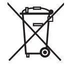 Caution! – some parts of the product may contain pollutants or hazardous substances which, if disposed of into the environment, may cause serious damage to the environment or physical health.
As indicated by the symbol alongside, disposal of this product in domestic waste is strictly prohibited. Separate the waste into
categories for disposal, according to the methods envisaged by current legislation in your area, or return the product to the retailer
when purchasing a new version.
Caution! – local legislation may envisage serious fines in the event of abusive disposal of this product.
PLACE FOR CE
DECLARATION
Nice SpA
Oderzo TV Italia
[email protected]
www.niceforyou.com
IST343A.4858_08-09-2015


