Honeywell FocusPRO 5000 Thermostat
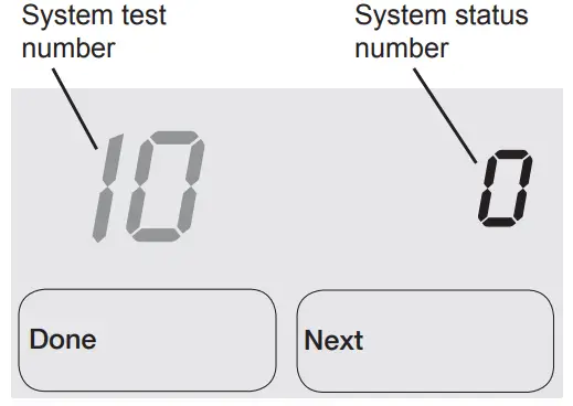
INSTALLER SYSTEM TEST
FocusPRO® 5000 Series
- To begin, press and hold the
 buttons until the display changes.
- Press
 to turn system on/off
- Press NEXT to advance to next test.
- Press DONE to terminate system test.
- Proceed to Installer System Tests on page 8.

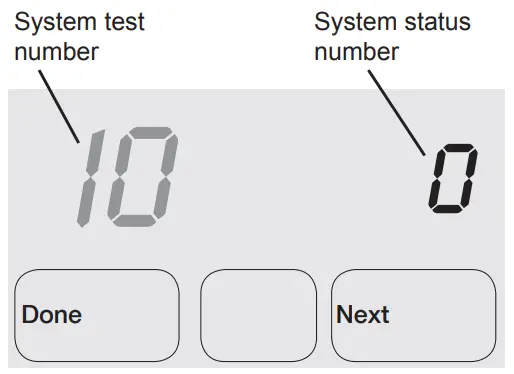
FocusPRO® 6000 Series
- To begin, press and hold the buttons until the display changes.

- Press to turn system on/off

- Press NEXT to advance to next test.
- Press DONE to terminate system test.
- Proceed to Installer System Tests on page 8.

Test the system’s heating, emergency heat, cooling, and fan.
Available tests vary by thermostat and system type.
| Table 2. Installer System Test | |||
| System Test Number | Test Type | System Status Number and Description | |
| 10 | Heating system | 0 | Heat and fan off |
| 1 | First stage heat | ||
| on (Fan turns on if | |||
| Setup Function 1 is | |||
| set to 1, 5, 9, or 10 | |||
| OR setup Function | |||
| 3 is set to 1) | |||
| 2 | Second stage heat | ||
| on | |||
| 3 | Third stage heat | ||
| on | |||
| 20 | Emergency heating system | 0 1 2 | Heat and fan off Heat and fan on Second stage heat (Aux. heat) turns on |
| 30 | Cooling system | 0 | Compressor and |
| fan off | |||
| 1 | Compressor and | ||
| fan on | |||
| 2 | Second stage | ||
| compressor on | |||
| 40 | Fan system | 0 | Off |
| 1 | On | ||
caution
- EQUIPMENT DAMAGE HAZARD.
- Compressor protection is bypassed during testing.
- To prevent equipment damage, avoid cycling the compressor quickly.
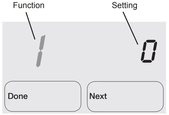
INSTALLER SETUP
FocusPRO® 5000 Series
- To begin, press and hold the
 and FAN buttons until the display changes.
- Press
 to change settings
- Press NEXT to advance to the next function.
- Press DONE to exit and save settings.
- Proceed to Installer Setup Functions on page 4.

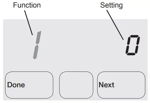
FocusPRO® 6000 Series
- To begin, press and hold the and FAN buttons until the display changes.

- Press to change settings

- Press NEXT to advance to the next function.
- Press DONE to exit and save settings.
- Proceed to Installer Setup Functions on page 4.

Available option and default settings vary by thermostat.
| Table 1. Installer Setup | |||
| Setup functions | Setting & Options (factory default in bold) | ||
| 1 | System type | 0 | 1 heat / 1 cool Conv. |
| 1 | 1 heat / 1 cool heat | ||
| pump (no Aux. heat) | |||
| 2 | Heat only (2-wire, 3-wire | ||
| zone valves [Series 20], | |||
| and normally open zone | |||
| valves) | |||
| 3 | Heat only with fan | ||
| 4 | Cool only | ||
| 5 | 2 heat / 1 cool heat | ||
| pump (with Aux. heat) | |||
| 6 | 2 heat / 2 cool Conv. | ||
| 7 | 2 heat / 1 cool Conv. | ||
| 8 | 1 heat / 2 cool Conv. | ||
| 9 | 2 heat / 2 cool heat pump | ||
| (no Aux. heat) | |||
| 10 | 3 heat / 2 cool heat | ||
| pump (with Aux. heat) | |||
| 2 | Changeover valve | 0 | Controls valve in cooling |
| (O/B terminal) | 1 | Controls valve in heating | |
| 3 | Fan control (heating) | 0
1 | Gas/Oil heat (equipment controls heating fan) Electric furnace (thermo- stat controls heating fan) |
| 5 | First stage heat | 5 | Gas or oil furnaces of |
| cycle rate | less than 90% | ||
| efficiency | |||
| 1 | Steam or gravity | ||
| 3 | Hot water systems or fur- | ||
| naces of 90%+ efficiency | |||
| 9 | Electric furnaces | ||
| [Other options: 1–12] | |||
| 6 | Second stage | 5 | Gas or oil furnaces of |
| heat/Aux heat | less than 90% efficiency | ||
| cycle rate | 1 | Steam or gravity | |
| 3 | Hot water systems or fur- | ||
| naces of 90%+ efficiency | |||
| 9 | Electric furnaces | ||
| [Other options: 1–12] | |||
| 7 | Auxiliary heat | 5 | Gas or oil furnaces of |
| cycle rate | less than 90% efficiency | ||
| 1 | Steam or gravity | ||
| 3 | Hot water systems or fur- | ||
| naces of 90%+ efficiency | |||
| 9 | Electric furnaces | ||
| [Other options: 1–12] | |||
| 8 | Emergency heat | 9 | Electric emergency heat |
| cycle rate | 1 | Steam or gravity | |
| 3 | Hot water systems or fur- | ||
| naces of 90%+ efficiency | |||
| 5 | Gas or oil furnaces of | ||
| less than 90% efficiency | |||
| [Other options: 1–12] | |||
| 9 | First stage compressor cycle rate | 3 | Recommended [Other options: 1–6] |
| 10 | Second stage compressor cycle rate | 3 | Recommended [Other options: 1–6] |
| 12 | Manual/Auto | 0 | Manual changeover |
| changeover | (Heat/Cool/Off) | ||
| 1 | Auto changeover (Heat/ | ||
| Cool/Auto/Off) | |||
| 2 | Auto changeover only | ||
| (Auto) | |||
| 13 | Adaptive Intel- | 1 | On |
| ligent RecoveryTM | 0 | Off | |
| 14 | Temperature | 0 | Fahrenheit |
| display | 1 | Celsius | |
| 15 | Compressor protection | 5 | 5-minute compressor off time [Other options: 0–4 minutes] |
| 16 | Schedule format | 0
1 | 5/2 (weekdays and weekends programmable) 5/1/1 (weekdays, Saturday, and Sunday programmable) |
| 26 | Auxiliary heat | 0 | Comfort |
| control | 1 | Economy | |
| 27 | Heat temperature range stops | 90 | Max. heat temperature setting is 90°F (32°C) [Other options: 40–89°F (4.5°C to 32°C)] |
| 28 | Cool temperature range stop | 50 | Min. cool temperature setting is 50°F (10°C) [Other options: 51–99°F (10.5°C to 37°C)] |
ABOUT COMPANY
- Automation and Control Solutions
- Honeywell International Inc.
- 1985 Douglas Drive North
- Golden Valley, MN 55422
- Honeywell Limited-Honeywell Limitée
- 35 Dynamic Drive
- Toronto, Ontario M1V 4Z9
- http://yourhome.honeywell.com


