
 TRAIL GRID PRO 4RUN-RAPTOR-WHITE-14-21 Toyota 4Runner Raptor Lights

Raptor Light Install Supporting Documentation
UPDATE: Use the video as a reference but the new kit no longer requires the routing of wires through the firewall.
Full Raptor Light Install Video QR Code
Scan the QR code below to access our install video or visit our YouTube Channel here: https://youtu.be/_G6NCpBN6pE
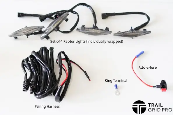
Included In Your Raptor Light Kit 
Step 1: Crimp the ring terminal to the black wire. Crimp the add-a-fuse to the red wire. Ensure a snug connection by pulling gently on your wires. Using a heat gun, you may also heat up and shrink the insulation on the ring terminal and butt connector to further secure the wires.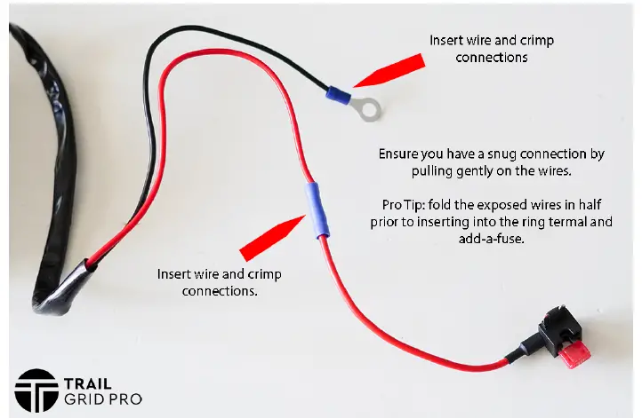
Step 2: Insert the Raptor Lights into the desired locations on your grille. Insert the wire end through the hole first and gently push the light into place. If the light doesn’t seem to be secure, try rotating the light 180 degrees. The tabs should all lock into place.
Repeat for all 4 lights.
Step 3: Connect all 4 lights to the provided wiring harness. The connections are keyed and will only connect one way. Route the power and ground wire behind the driver’s side headlight and toward the fuse panel located behind the battery.
Step 4: Install add-a-fuse into the INJ fuse located in the fuse box under the hood near the driver-side fender. Remove the 10 amp fuse that is located in the INJ location and place into the empty slot on the add-a-fuse. Place the add-a-fuse back into the INJ fuse location.
NOTE: Alternate fuse locations (EFI No.2, H-lp LH, H-lp RH) You may choose to cut a small notch in the bottom the fuse box lid so that the fuse cover will close tightly without smashing the red power wire. Secure the ring terminal from the black wire to the 10mm ground bolt. It is located near the battery on the inside of the driver’s side fender.


