![]()
Wireless Door Bell Button
ModelR313M
Wireless Door Bell Button
User Manual
Copyright©Netvox Technology Co., Ltd.
This document contains proprietary technical information which is the property of NETVOX Technology. It shall be maintained in strict confidence and shall not be disclosed to other parties, in whole or in part, without written permission of NETVOX Technology. The specifications are subject to change without prior notice.
Introduction
The R313M is a doorbell button device for Netvox ClassA type devices based on the LoRaWAN open protocol and is compatible with the LoRaWAN protocol.
LoRa Wireless Technology:
Lora is a wireless communication technology dedicated to long-distance and low power consumption. Compared with other communication methods, the LoRa spread spectrum modulation method greatly increases to expand the communication distance. Widely used in long-distance, low-data wireless communications. For Examples, automatic meter reading, building automation equipment, wireless security systems, and industrial monitoring. Main features include small size, low power consumption, transmission distance, anti-interference ability, and so on.
LoRaWAN:
LoRaWAN uses LoRa technology to define end-to-end standard specifications to ensure interoperability between devices and gateways from different manufacturers.
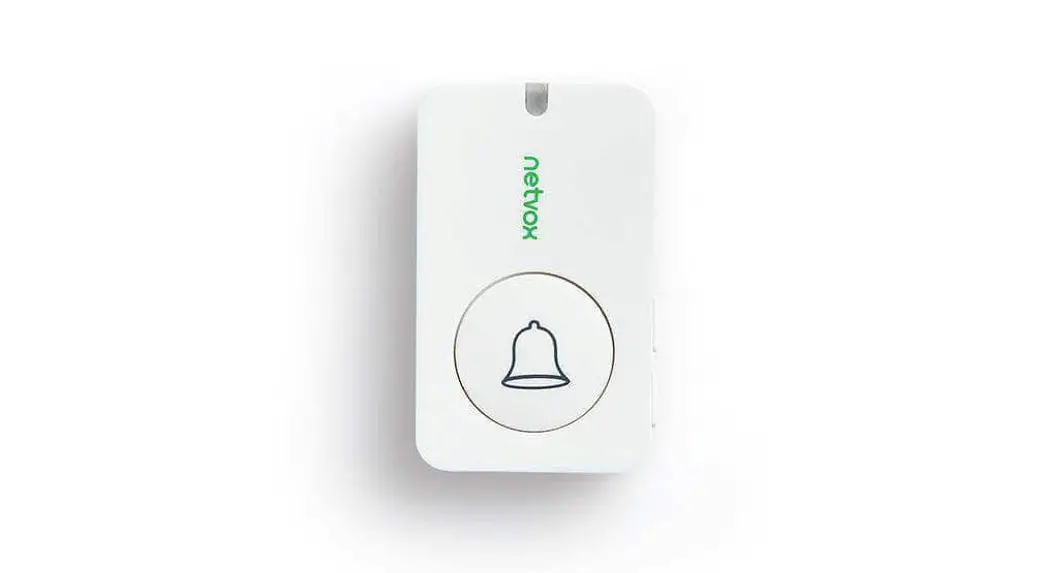
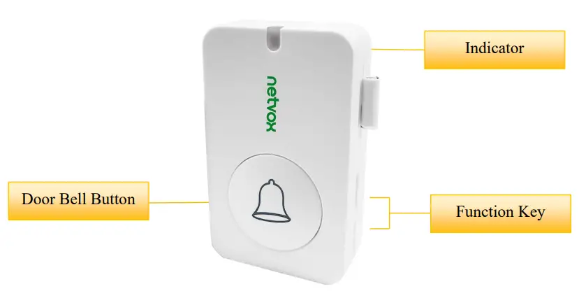
Appearance
Main Features
- Compatible with LoRaWAN
- 2 sections of 3V CR2450 button battery power supply
- Doorbell status detection
- Simple operation and setting
- Protection class IP30
- Compatible with LoRaWAN™Class A
- Frequency-hopping spread spectrum
- Configuration parameters can be configured via a third-party software platform, data can be read and alerts can be set via SMS text and email (optional)
- Applicable to third-party platforms: Actility/ThingPark, TTN, MyDevices/Cayenne
- Improved power management for longer battery life Battery Life
⁻Please refer to the web: http://www.netvox.com.tw/electric/electric_calc.html
⁻On this website, users can find battery lifetime for various models at different configurations.
1. Actual range may vary depending on the environment.
2. Battery life is determined by sensor reporting frequency and other variables.
Set up Instruction
On/Off
| Power on | Insert batteries (users may need a screwdriver to open) Insert two sections of 3V CR2450 button batteries and close the battery cover. Note: Require 2 button batteries to supply power at the same time. |
| Turn on | Press any function key and the indicator flashes once meaning it is turned on successfully. |
| Turn off (Restore to factory setting) | Press and hold the function key for 5 seconds and the green indicator flashes 20 times. |
| Power off | Remove Batteries. |
| Note: | 1. Remove and insert the battery; the device memorizes the previous on/off state by default. 2. On/off interval is suggested to be about 10 seconds to avoid the interference of capacitor inductance and other energy storage components. 3. If press any function key and insert batteries at the same time, it will enter engineer testing mode. |
Network Joining
| Never joined the network | Turn on the device to search the network. The green indicator stays on for 5 seconds: success The green indicator remains off: fail |
| Had joined the network (not restored to the factory setting) | Turn on the device to search the previous network. The green indicator stays on for 5 seconds: success The green indicator remains off: fail |
| Fail to join the network | Suggest checking the device verification information on the gateway or consulting your platform service provider. |
Function Key
| Press and hold for 5 seconds | Restore to factory setting / Turn off The green indicator flashes 20 times: success The green indicator remains off: fail |
| Press once | The device is in the network: green indicator flashes once and sends a report The device is not in the network: the green indicator remains off |
| Press doorbell button | Trigger the doorbell alarm Note: Users can configure the button pressing time to send an alarm by command |
Sleeping Mode
| The device is on and in the network | Sleeping period: Min Interval. When the report change exceeds the setting value or the state changes: send a data report according to Min Interval. |
Low Voltage Warning
| Low Voltage | 2.4V |
Data Report
The device will immediately send a version packet report along with an uplink packet including the doorbell alarm.
The device sends data in the default configuration before any configuration is done.
Default setting
Maximum time: 3600s
Minimum time: 3600s
Battery change: 0x01 (0.1v)
Doorbell button trigger:
Press the doorbell button and immediately send a report.
R313M was pressed, Alarm=1
R313M was not pressed, Alarm=0
Note:
interval is the sampling period for the Sensor. Sampling period >= MinInterval.
Please refer Netvox LoRaWAN Application Command document and Netvox Lora Command
Resolver http://loraresolver.netvoxcloud.com:8888/page/index to resolve uplink data.
Data report configuration and sending period are as follows:
| Min Interval (Unit: second) | Max Interval (Unit: second) | Reportable Change | Current Change? Reportable Change | Current Change< Reportable Change |
| Any number between 1-65535 | Any number between 1-65535 | Can not be 0. | Report per \ 1 in Interval | Report per Max Interval |
Example of ConfigureCmd
port :0x07
| Bytes | 1 | 1 | Var (Fix =9 Bytes) |
| CmdID | DeviceType | NetvoxPayLoadData |
CmdID- 1 byte
DeviceType— 1 byte — Device Type of Device
NetvoxPayLoadData— var bytes (Max=9bytes)
| Description | Device | mCd ID | Device Teyp | NetvoxPayLoadData | ||||
| Config ReportReq | R313M | Ox01 | 0x55 | MinTime (2bytes Unit:s) | MaxTime (2bytes Unit:s) | Battery Change ( byte Unit:0.1v) | Reserved (4Bytes,Fixed Ox00) | |
| Config ReportRsp | 0x81 | Status (0x00 success) | Reserved (8Bytes,Fixed Ox00) | |||||
| ReadConfig ReportReq | 0x02 | Reserved (9Bytes,Fixed Ox00) | ||||||
| ReadConfig ReportRsp | 0x82 | MinTime (2bytes Unit:s) | MaxTime (2bytes Unit:s) | Battery Change (]byte Unit:0.1v) | Reserved (4Bytes,Fixed Ox00) | |||
- Command Configuration:
MinTime = 1min、MaxTime = 1min、BatteryChange = 0.1v
Downlink :
0155003C003C0100000000
003C(Hex) = 60(Dec)
Response:
8155000000000000000000 (Configuration success )
8155010000000000000000 (Configuration failure) - Read Configuration:
Downlink:
0255000000000000000000
Response:
8255003C003C0100000000 (Current configuration )
Example of Config Button Press Time
FPort :0x0D
Default Press Time:0x00
| I)ecript ion | CmdID | PayLoad(Fix byte,lbyte) |
| SetButtonPressTimeReq | Ox01 | PressTime (1 bytes) Ox0O_QuicicPush Less then 1 Second, Ox01 1 Second push, 0x02_2 Seconds push, 0x03_3 Seconds push, 0x04_4 Seconds push, 0x05_5 Seconds push, Other value is reserved |
| SetButtonPressTimeRsp | 0x81 | Status (0x00 Success Ox01 Failure) |
| GetButtonPressTitneReq | 0x02 | |
| GetButtonPressTimeRsp | 0x82 | PressTime (lbytes) Ox0O_QuicicPush Less then 1 Second,Ox01 1 Second push, 0x02_2 Seconds push, 0x03_3 Seconds push, 0x04_4 Seconds push, 0x05_5 Seconds push, Other value is reserved |
- Command Configuration:
Trigger door bell after press button 2 seconds
Downlink :0102
*Please notice port number is 0x0D (13) when downlink command
Response:
8100 (Configuration success)
8101 (Configuration failure) - Read Configuration:
Downlink:02
Response:8202 (Current configuration)
Example for MinTime/MaxTime logic
Example#1 based on MinTime = 1 Hour, MaxTime= 1 Hour, Reportable Change
i.e.BatteryVoltageChange=0.1V
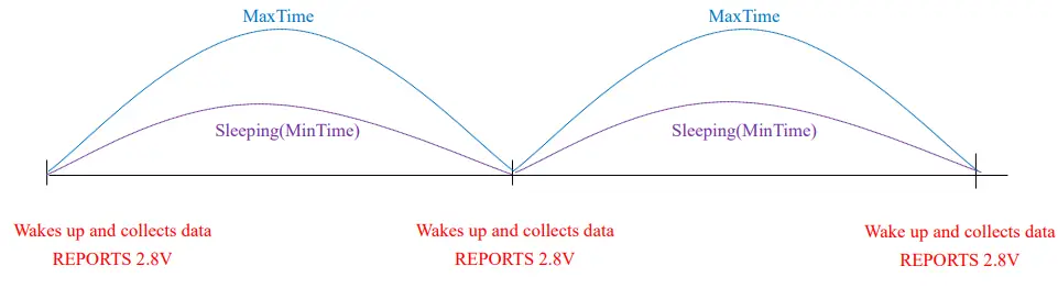
Note:
MaxTime=MinTime. Data will only be report according to MaxTime (MinTime) duration regardless BtteryVoltageChange value.
Example#2 based on MinTime = 15 Minutes, MaxTime= 1 Hour, Reportable Change i.e. BatteryVoltageChange= 0.1V.
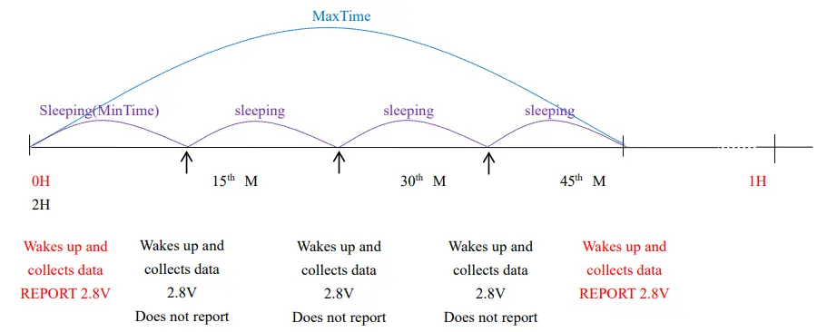
Example#3 based on MinTime = 15 Minutes, MaxTime= 1 Hour, Reportable Change
i.e. BatteryVoltageChange= 0.1V.
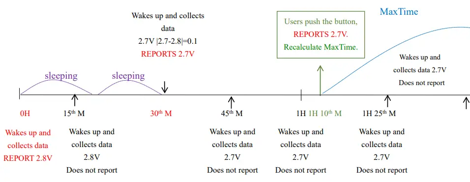
Notes:
- The device only wakes up and performs data sampling according to MinTime Interval.
When it is sleeping, it does not collect data. - The data collected is compared with the last data reported. If the data change value is greater than the ReportableChange value, the device reports according to the MinTime interval.
If the data variation is not greater than the last data reported, the device reports according to the Maxime interval. - We do not recommend setting the MinTime Interval value too low. If the MinTime Interval is too low, the device wakes up frequently and the battery will be drained soon.
- Whenever the device sends a report, no matter the resulting of data variation, button push or Maxime interval, another cycle of MinTime/Maxime calculation is started.
Installation
- This product does not have a waterproof function. After the screening is completed, please place
it indoors. - The dust at the equipment installation position needs to be wiped clean and then pasted.
- The battery installation method is as shown below (the battery has a “+” side facing outward)
(Users may need a flat blade screwdriver to open the battery cover.)
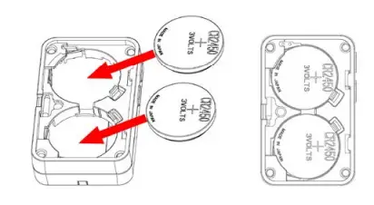
| 1. Remove the 3M release paper on the back of the device and attach the device to the smooth wall (please do not stick it to the rough wall to avoid falling off after a long time of use). Note:
| 2. When the doorbell (R313M) button is pressed, the message “Alarm” is sent. When the device reports data periodically, it restores the “normal” status and sends “normal” status information. Note: With the sound and light alarm (R602A), the audible and visual alarm will ring the door after the doorbell is pressed. |
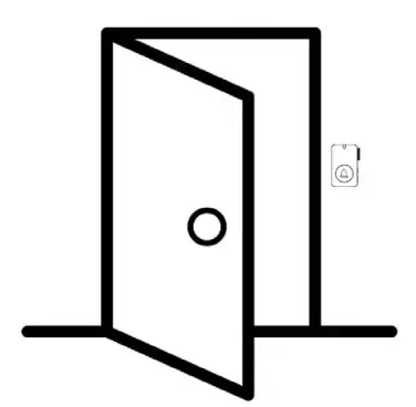
The figure shows the smart Doorbell Button (R313M) applied to the home entrance door scene.
It can also be applied to the following scenarios:
- Villa
- Office front desk
- Hotel
- Apartment
Important Maintenance Instruction
Kindly pay attention to the following in order to achieve the best maintenance of the product:
- Keep the device dry. Rain, moisture, or any liquid, might contain minerals and thus corrode electronic circuits. If the device gets wet, please dry it completely.
- Do not use or store the device in a dusty or dirty environment. It might damage its detachable parts and electronic components.
- Do not store the device under excessive heat conditions. High temperature can shorten the life of electronic devices, destroy batteries, and deform or melt some plastic parts.
- Do not store the device in places that are too cold. Otherwise, when the temperature rises to normal temperature, moisture will form inside, which will destroy the board.
- Do not throw, knock or shake the device. Rough handling of equipment can destroy internal circuit boards and delicate structures.
- Do not clean the device with strong chemicals, detergents or strong detergents.
- Do not apply the device with paint. Smudges might block in the device and affect the operation.
- Do not throw the battery into the fire, or the battery will explode. Damaged batteries may also explode.
All of the above applies to your device, battery and accessories. If any device is not working properly, please take it to the nearest authorized service facility for repair.


