![]() IdeaPad 5 14ABA7 Cloud Grey
IdeaPad 5 14ABA7 Cloud Grey
User Guide
 IdeaPad 5i (14″, 7), IdeaPad 5 (14″, 7), IdeaPad 5i (15″, 7) and IdeaPad 5 (15″, 7)
About this manual
This manual contains service and reference information for the following Lenovo products.
| Model name | Machine type (MT) |
| IdeaPad 5 14IAL7 | 82SD |
| IdeaPad 5 14ABA7 | 82SE |
| IdeaPad 5 15IAL7 | 82SF |
| IdeaPad 5 15ABA7 | 82SG |
Important:
- This manual is intended only for trained service technicians who are familiar with Lenovo products.
- Before servicing a Lenovo product, be sure to read all the information under Chapter 1 “Safety information” on page 1.
Chapter 1. Safety information
This chapter presents the following safety information that you need to be familiar with before you service a Lenovo notebook computer.
General safety
Follow these rules to ensure general safety:
- Observe good housekeeping in the area of the machines during and after maintenance.
\When lifting any heavy object:
1. Make sure that you can stand safely without slipping.
2. Distribute the weight of the object equally between your feet.
3. Use a slow lifting force. Never move suddenly or twist when you attempt to lift.
4. Lift by standing or by pushing up with your leg muscles; this action removes the strain from the muscles in your back. Do not attempt to lift any object that weighs more than 16 kg (35 lb) or that you think is too heavy for you. - Do not perform any action that causes hazards to the customer, or that makes the equipment unsafe.
- Before you start the machine, make sure that other service technicians and the customer’s personnel are not in a hazardous position.
- Place removed covers and other parts in a safe place, away from all personnel, while you are servicing the machine.
- Keep your tool case away from walk areas so that other people will not trip over it.
- Do not wear loose clothing that can be trapped in the moving parts of a machine. Make sure that your sleeves are fastened or rolled up above your elbows. If your hair is long, fasten it.
- Insert the ends of your necktie or scarf inside clothing or fasten it with a non-conductive clip, about 8 centimeters (3 inches) from the end.
- Do not wear jewelry, chains, metal-frame eyeglasses, or metal fasteners for your clothing.
Attention: Metal objects are good electrical conductors. - Wear safety glasses when you are hammering, drilling, soldering, cutting wire, attaching springs, using solvents, or working in any other conditions that might be hazardous to your eyes.
- After service, reinstall all safety shields, guards, labels, and ground wires. Replace any safety device that is worn or defective.
- Reinstall all covers correctly before returning the machine to the customer.
- Fan louvers on the machine help to prevent overheating of internal components. Do not obstruct fan louvers or cover them with labels or stickers.
Electrical safety
Observe the following rules when working on electrical equipment.
Important: Use only approved tools and test equipment. Some hand tools have handles covered with a soft material that does not insulate you when working with live electrical currents. Many customers have, near their equipment, rubber floor mats that contain small conductive fibers to decrease electrostatic discharges.
Do not use this type of mat to protect yourself from electrical shock.
- Find the room emergency power-off (EPO) switch, disconnecting switch, or electrical outlet. If an electrical accident occurs, you can then operate the switch or unplug the power cord quickly.
- Do not work alone under hazardous conditions or near equipment that has hazardous voltages.
- Disconnect all power before:
– Performing a mechanical inspection
– Working near power supplies
– Removing or installing main units - Before you start to work on the machine, unplug the power cord. If you cannot unplug it, ask the customer to power off the wall box that supplies power to the machine, and to lock the wall box in the off position.
- If you need to work on a machine that has exposed electrical circuits, observe the following precautions:
– Ensure that another person, familiar with the power-off controls, is near you.
Attention: Another person must be there to switch off the power, if necessary.
– Use only one hand when working with powered-on electrical equipment; keep the other hand in your pocket or behind your back.
Attention: An electrical shock can occur only when there is a complete circuit. By observing the above rule, you may prevent a current from passing through your body.
– When using testers, set the controls correctly and use the approved probe leads and accessories for that tester.
– Stand on suitable rubber mats (obtained locally, if necessary) to insulate you from grounds such as metal floor strips and machine frames.
Observe the special safety precautions when you work with very high voltages; Instructions for these precautions are in the safety sections of maintenance information. Use extreme care when measuring high voltages. - Regularly inspect and maintain your electrical hand tools for safe operational conditions.
- Do not use worn or broken tools and testers.
- Never assume that power has been disconnected from a circuit. First, check that it has been powered off.
- Always look carefully for possible hazards in your work area. Examples of these hazards are moist floors, non-grounded power extension cables, power surges, and missing safety grounds.
- Do not touch live electrical circuits with the reflective surface of a plastic dental mirror. The surface is conductive; such touching can cause personal injury and machine damage.
- Do not service the following parts with the power on when they are removed from their normal operating places in a machine:
– Power supply units
– Pumps
– Blowers and fans
– Motor generators
– Similar units as listed above
This practice ensures the correct grounding of the units. - If an electrical accident occurs:
– Use caution; do not become a victim yourself.
– Switch off the power.
– Send another person to get medical aid.
Safety inspection guide
The purpose of this inspection guide is to assist you in identifying potentially unsafe conditions. As each machine was designed and built, required safety items were installed to protect users and service technicians from injury. This guide addresses only those items. You should use good judgment to identify potential safety hazards due to the attachment of non-Lenovo features or options not covered by this inspection guide.
If any unsafe conditions are present, you must determine how serious the apparent hazard could be and whether you can continue without first correcting the problem.
Consider these conditions and the safety hazards they present:
- Electrical hazards, especially primary power (primary voltage on the frame can cause serious or fatal electrical shock)
- Explosive hazards, such as a damaged cathode ray tube (CRT) face or a bulging capacitor
- Mechanical hazards, such as loose or missing hardware
To determine whether there are any potentially unsafe conditions, use the following checklist at the beginning of every service task. Begin the checks with the power off, and the power cord disconnected.
Checklist:
- Check exterior covers for damage (loose, broken, or sharp edges).
- Power off the computer. Disconnect the power cord.
- Check the power cord for:
a. A third-wire ground connector in good condition. Use a meter to measure third-wire ground continuity for 0.1 ohms or less between the external ground pin and the frame ground.
b. The power cord should be the authorized type specified for your computer. Go to: http://www.lenovo.com/serviceparts-lookup
c. Insulation must not be frayed or worn. - Check for cracked or bulging batteries.
- Remove the cover.
- Check for any obvious non-Lenovo alterations. Use good judgment as to the safety of any non-Lenovo alterations.
- Check inside the unit for any obvious unsafe conditions, such as metal filings, contamination, water or other liquids, or signs of fire or smoke damage.
- Check for worn, frayed, or pinched cables.
- Check that the power-supply cover fasteners (screws or rivets) have not been removed or tampered with.
Handling devices that are sensitive to electrostatic discharge
Any computer part containing transistors or integrated circuits (ICs) should be considered sensitive to electrostatic discharge (ESD). ESD damage can occur when there is a difference in charge between objects.
Protect against ESD damage by equalizing the charge so that the machine, the part, the work mat, and the person handling the part are all at the same charge.
Notes:
- Use product-specific ESD procedures when they exceed the requirements noted here.
- Make sure that the ESD protective devices you use have been certified (ISO 9000) as fully effective.
When handling ESD-sensitive parts:
- Keep the parts in protective packages until they are inserted into the product.
- Avoid contact with other people.
- Wear a grounded wrist strap against your skin to eliminate static on your body.
- Prevent the part from touching your clothing. Most clothing is insulative and retains a charge even when you are wearing a wrist strap.
- Use a grounded work mat to provide a static-free work surface. The mat is especially useful when handling ESD-sensitive devices.
- Select a grounding system, such as those listed below, to provide protection that meets the specific service requirement.
Note: The use of a grounding system to guard against ESD damage is desirable but not necessary.
- Attach the ESD ground clip to any frame ground, ground braid, or green-wire ground.
- When working on a double-insulated or battery-operated system, use an ESD common ground or reference point. You can use coax or connector-outside shells on these systems.
- Use the round ground prong of the ac plug on ac-operated computers.
Grounding requirements
Electrical grounding of the computer is required for operator safety and correct system function. Proper grounding of the electrical outlet can be verified by a certified electrician.
Safety notices (multilingual translations)
The safety notices in this section are provided in the following languages:
- English
- Arabic
- Brazilian Portuguese
- French
- German
- Hebrew
- Japanese
- Korean
- Spanish
- Traditional Chinese

DANGER
Before the computer is powered on after FRU replacement, make sure that all screws, springs, and other small parts are in place and are not left loose inside the computer. Verify this by shaking the computer and listening to rattling sounds. Metallic parts or metal flakes can cause electrical short circuits.
DANGER
Some standby batteries contain a small amount of nickel and cadmium. Do not disassemble a standby battery, recharge it, throw it into fire or water, or short-circuit it. Dispose of the battery as required by local ordinances or regulations. Use only the battery in the appropriate parts listing. Use of an incorrect battery can result in ignition or explosion of the battery.
DANGER
The battery pack contains small amounts of nickel. Do not disassemble it, throw it into fire or water, or short-circuit it. Dispose of the battery pack as required by local ordinances or regulations. Use only the battery in the appropriate parts listing when replacing the battery pack. Use of an incorrect battery can result in ignition or explosion of the battery.
DANGER
The lithium battery can cause a fire, an explosion, or a severe burn. Do not recharge it, remove its polarized connector, disassemble it, heat it above 100°C (212°F), incinerate it, or expose its cell contents to water.
Dispose of the battery as required by local ordinances or regulations. Use only the battery in the appropriate parts listing. Use of an incorrect battery can result in ignition or explosion of the battery.
DANGER
If the LCD breaks and the fluid from inside the LCD gets into your eyes or on your hands, immediately wash the affected areas with water for at least 15 minutes. Seek medical care if any symptoms from the fluid are present after washing.
DANGER
To avoid shock, do not remove the plastic cover that protects the lower part of the inverter card.
DANGER
Though the main batteries have low voltage, a short-circuited or grounded battery can produce enough current to burn personnel or combustible materials.
DANGER
Unless a hot swap is allowed for the FRU to be replaced, do as follows before removing it: power off the computer, unplug all power cords from electrical outlets, remove the battery pack, and disconnect any interconnecting cables.
Chapter 2. General checkout
This chapter contains the following topics:
Before you go to the checkout instructions, ensure that you read the following important notes.
Important notes:
- Only certified trained personnel should service the computer.
- Before replacing any FRU, read the entire page on removing and replacing FRUs.
- Be extremely careful during such write operations as copying, saving, or formatting. The drives in the computer
that you are servicing sequence might have been altered. If you select an incorrect drive, data or programs might be overwritten. - Replace an FRU only with another FRU of the correct model. When you replace an FRU, make sure that the model of the machine and the FRU part number are correct by referring to the FRU parts list.
- An FRU should not be replaced because of a single, unreproducible failure. Single failures can occur for a variety of reasons that have nothing to do with a hardware defect, such as cosmic radiation, electrostatic discharge, or software errors. Consider replacing an FRU only when a problem recurs. If you suspect that an FRU is defective, clear the error log and run the test again. If the error does not recur, do not replace the FRU.
- Be careful not to replace a nondefective FRU.
What to do first
When you return an FRU, you must include the following information in the parts exchange form or parts return form that you attach to it:
- Name and phone number of service technician
- Date of service
- Date on which the machine failed
- Date of purchase
- Failure symptoms, error codes appearing on the display, and beep symptoms
- Procedure index and page number in which the failing FRU was detected
- Failing FRU name and part number
- Machine type, model number, and serial number
- Customer’s name and address
Note: During the warranty period, the customer may be responsible for repair costs if the computer damage was caused by misuse, accident, modification, unsuitable physical or operating environment, or improper maintenance by the customer. Following is a list of some common items that are not covered under warranty and some symptoms that might indicate that the system was subjected to stress beyond normal use.
Before checking problems with the computer, determine whether the damage is covered under the warranty by referring to the following list:
The following are not covered under warranty:
- LCD panel cracked from the application of excessive force or from being dropped
- Scratched (cosmetic) parts
- Distortion, deformation, or discoloration of the cosmetic parts
- Plastic parts, latches, pins, or connectors that have been cracked or broken by excessive force
- Damage caused by liquid spilled into the system
- Damage caused by the improper insertion of a personal computer card (PC card) or the installation of an incompatible card
- Improper disc insertion or use of an external optical drive
- Fuses blew by attachment of a non-supported device
- Forgotten computer password (making the computer unusable)
- Sticky keys caused by spilling a liquid onto the keyboard
- Use of an incorrect ac power adapter on laptop products
The following symptoms might indicate damage caused by non-warranted activities:
- Missing parts might be a symptom of unauthorized service or modification.
- Check for obvious damage to a hard disk drive. If the spindle of a hard disk drive becomes noisy, the hard disk drive might have been dropped or subject to excessive force.
CRU list
Table 1. Models: IdeaPad 5 14IAL7 (MT: 82SD)
| CRU | Type |
| ac power adapter | self-service |
| Power cord | self-service |
Table 2. Models: IdeaPad 5 14ABA7 (MT: 82SE)
| CRU | Type |
| ac power adapter | self-service |
| Power cord | self-service |
Table 3. Models: IdeaPad 5 15IAL7 (MT: 82SF)
| CRU | Type |
| ac power adapter | self-service |
| Power cord | self-service |
Chapter 3. Identifying FRUs (CRUs)
Locate FRUs and CRUs
The exploded illustrations help Lenovo service technicians identify FRUs or CRUs that they may need to replace when servicing a customer’s computer.
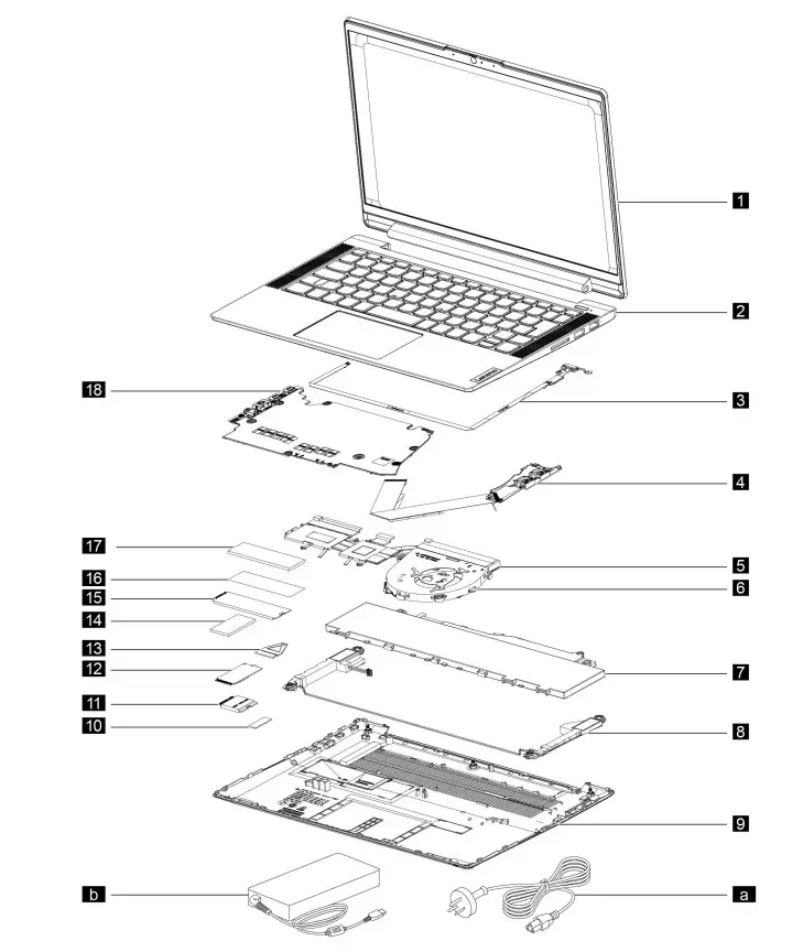 Figure 1. 14-inch models – Exploded view
Table 5. FRU (CRU) categories
| No. | FRU (CRU) category |
| 1 | LCD module Note: The LCD module as a whole is not an FRU, it contains FRUs as its components. |
| 2 | Upper case |
| 3 | Fingerprint board with cable |
| 4 | I/O board with cable |
| 5 | Heat sink |
| 6 | Fan |
| 7 | battery pack |
| 8 | Speakers |
| 9 | Lower case |
| 10 | Wi-Fi card mylar |
| 11 | Wi-Fi card |
| 12 | 2242 Solid-state drive (SSD) |
| 13 | Solid-state drive (SSD) bracket Note: The SSD bracket is used to lock the screw for the 2242 SSD. |
| 14 | 2242 Solid-state drive (SSD) thermalpad |
| 15 | 2280 Solid-state drive (SSD) |
| 16 | Solid-state drive (SSD) mylar |
| 17 | 2280 Solid-state drive (SSD) thermalpad |
| 18 | System board |
| a | Power cord |
| b | ac power adapter |
| c | Screw kit |
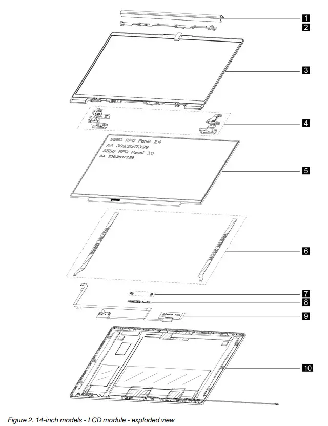
Table 6. FRU categories for the LCD module
| No. | FRU (CRU) category |
| 1 | Hinge cover |
| 2 | Hinge cover frame |
| 3 | LCD bezel |
| 4 | Hinges |
| 5 | LCD panel |
| 6 | Removable tape |
| 7 | Microphone rubbers |
| 8 | Camera board |
| 9 | EDP cable |
| 10 | LCD cover |
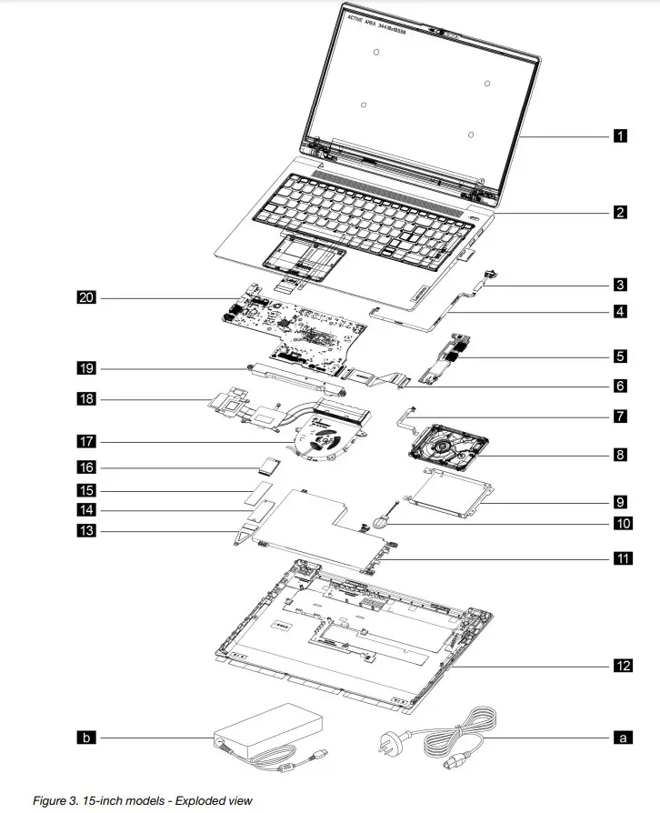
Table 7. FRU (CRU) categories
| No. | FRU (CRU) category |
| 1 | LCD module Note: The LCD module as a whole is not an FRU, it contains FRUs as its components. |
| 2 | Upper case |
| 3 | Fingerprint board |
| 4 | Fingerprint board cable |
| 5 | I/O board |
| 6 | I/O board cable |
| 7 | Hard disk drive (HDD) cable |
| 8 | Hard disk drive (HDD) |
| 9 | Hard disk drive (HDD) bracket |
| 10 | CMOS battery |
| 11 | Battery pack |
| 12 | Lower case |
| 13 | Solid-state drive (SSD) bracket Note: The SSD bracket is used to lock the screw for the 2242 SSD. |
| 14 | A solid-state drive (SSD) |
| 15 | Solid-state drive (SSD) thermalpad |
| 16 | Wi-Fi card |
| 17 | Fan |
| 18 | Heat sink |
| 19 | Speaker |
| 20 | System board |
| a | Power cord |
| b | ac power adapter |
| c | Screw kit |
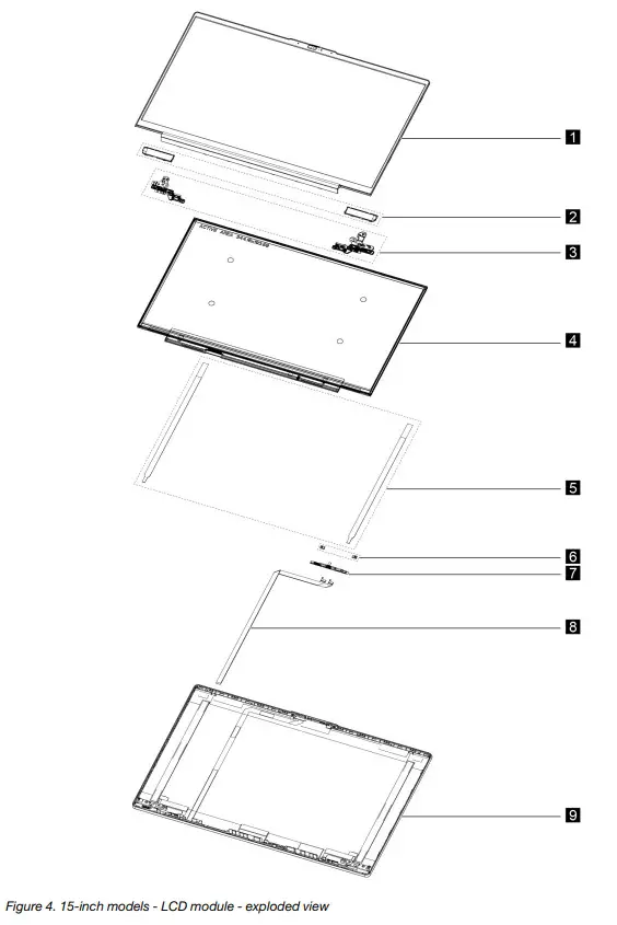
Table 8. FRU categories for the LCD module
| No. | FRU (CRU) category |
| 1 | LCD bezel |
| 2 | Strip cover |
| 3 | Hinges |
| 4 | LCD panel |
| 5 | Removable tape |
| 6 | Microphone rubbers |
| 7 | Camera board |
| 8 | EDP cable |
| 9 | LCD cover |
Chapter 4. Removing a FRU or CRU
Service tools
The following table lists tools for servicing Lenovo computers. Tools with a cross mark are needed for serving the product models as described by this publication. Prepare them before you service the product.
Table 9. Service tools
| Service tools and consumables | Model applicability |
| Screwdriver (Phillips’s head) (PH1/PH01) | X |
| Screwdriver (Torx head) (T5) | X |
| Screwdriver (Torx head) (T30) | |
| Pry tool 1 | X |
| Tweezers (conductive) | X |
| Tweezers (isolated) | |
| Suction cup | |
| Hexagonal socket | |
| Silicone grease | |
| Acetate tape | X |
| Polyamide tape | |
| Mylar tape | |
| Electrical tape | |
| Double-sided tape | |
| Conductive tape | |
| Eraser | |
| Heat gun | |
| Brown brush |
Notes:
- T30 screwdrivers are used to service the new Intel Xeon CPUs.
- Hexagonal sockets are used to remove antenna connectors.
- Silicone grease is applied to the CPU and heatsink surfaces to eliminate air gaps.
General guidelines
When removing or replacing an FRU, ensure that you observe the following general guidelines:
- Do not try to service any computer unless you have been trained and certified. An untrained person runs the risk of damaging parts.
- Begin by removing any FRUs that have to be removed before replacing the failing FRU. Any such FRUs are listed at the beginning of each FRU replacement procedure. Remove them in the order in which they are listed.
- Follow the correct sequence in the steps for removing an FRU, as shown in the illustrations by the numbers in square callouts.
- When removing an FRU, move it in the direction shown by the arrow in the illustration.
- To install a new FRU in place, perform the removal procedure in reverse and follow any notes that pertain to replacement.
- When replacing an FRU, carefully retain and reuse all screws.
- When replacing the base cover, reapply all labels that come with the replacement base cover. If some original labels are not included with the replacement base cover, peel them off from the original base cover and paste them on the replacement base cover.
DANGER
Before removing any FRU or CRU, shut down the computer and unplug all power cords from the electrical outlets.
Attention: After replacing an FRU, do not turn on the computer until you have ensured that all screws, springs, and other small parts are in place and none are loose inside the computer. Verify this by shaking the computer gently and listening to rattling sounds. Metallic parts or metal flakes can cause electrical short circuits.
Attention: The system board is sensitive to and can be damaged by ESD. Before touching it, establish personal grounding by touching a ground point with one hand or by using an ESD strap (P/N 6405959).
Removal procedure for 14-inch models
Remove the lowercase
Make sure the computer has been shut down before servicing the computer.
Step 1. Place the computer upside down on a flat surface.
Step 2. Loosen three screws and then remove four screws. 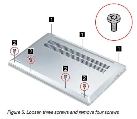
| Screw specifications | Number of screws |
| M2 x L3.5 | 4 |
Step 3. Pry up the latches and then remove the lowercase.
Go to https://support.lenovo.com/partslookup to look up the Lenovo part number of the following replacement part:
Remove the battery pack
Make sure the following FRU (or CRU) has been removed.
“Remove the lowercase” on page 34
Step 1. Disconnect the battery pack cable from the system board.
Attention: Use your fingernails to pull the connector to unplug it. Do not pull the cable.
Step 2. Remove two screws, release the speaker cable from the cable guide and then remove the battery pack. 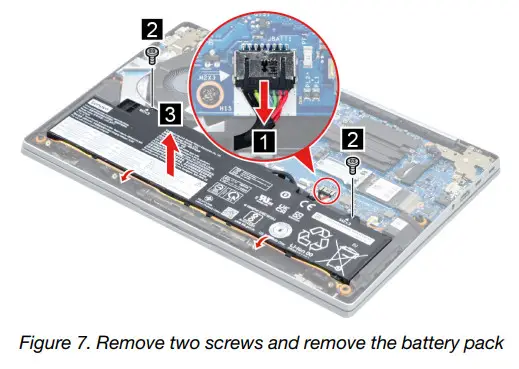
| Screw specifications | Number of screws |
| M2 x L3 | 2 |
Go to https://support.lenovo.com/partslookup to look up the Lenovo part number of the following replacement part: Battery pack
Remove the solid-state drive (SSD) module
Make sure the following FRU (or CRU) has been removed.
“Remove the lowercase” on page 34
Step 1. Disconnect the battery pack cable from the system board.
Attention: Use your fingernails to pull the connector to unplug it. Do not pull the cable.
Step 2. Remove one screw and then remove the SSD by pulling it away from the slot.
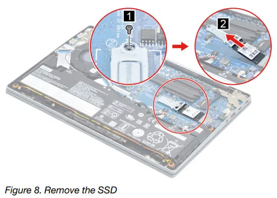
| Screw specifications | Number of screws |
| M2 x L3 | 1 |
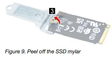
Step 3. Peel off the SSD mylar.
Step 4. Remove one screw and then remove the SSD and SSD bracket.
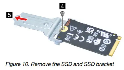
| Screw specifications | Number of screws |
| M2 x L2 | 1 |
Go to https://support.lenovo.com/partslookup to look up the Lenovo part numbers of the following replacement parts:
A solid-state drive (SSD)
Solid-state drive (SSD) mylar
Solid-state drive (SSD) bracket
Remove the Wi-Fi card
Make sure the following FRU (or CRU) has been removed.
“Remove the lowercase” on page 34
Step 1. Disconnect the battery pack cable from the system board.
Attention: Use your fingernails to pull the connector to unplug it. Do not pull the cable.
Step 2. Peel off the Wi-Fi card mylar. 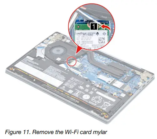
Step 3. Detach the main and auxiliary antenna cable connectors. Remove one screw and then remove the Wi-Fi card by pulling it away from the slot. 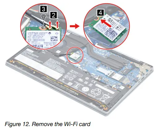
| Screw specifications | Number of screws |
| M2 x L3 | 1 |
Go to https://support.lenovo.com/partslookup to look up the Lenovo part numbers of the following replacement parts:
Wi-Fi card
Wi-Fi card mylar
Remove the heat sink
Make sure the following FRU (or CRU) has been removed.
“Remove the lowercase” on page 34
Step 1. Disconnect the battery pack cable from the system board.
Attention: Use your fingernails to pull the connector to unplug it. Do not pull the cable.
Step 2. Remove three screws and then remove the heat sink. 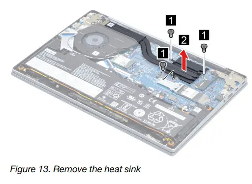
| Screw specifications | Number of screws |
| M2 x L3 | 3 |
Go to https://support.lenovo.com/partslookup to look up the Lenovo part number of the following replacement part: Heat sink
Remove the fan
Make sure the following FRU (or CRU) has been removed.
“Remove the lowercase” on page 34
“Remove the battery pack” on page 35
Step 1. Remove the I/O board cable. 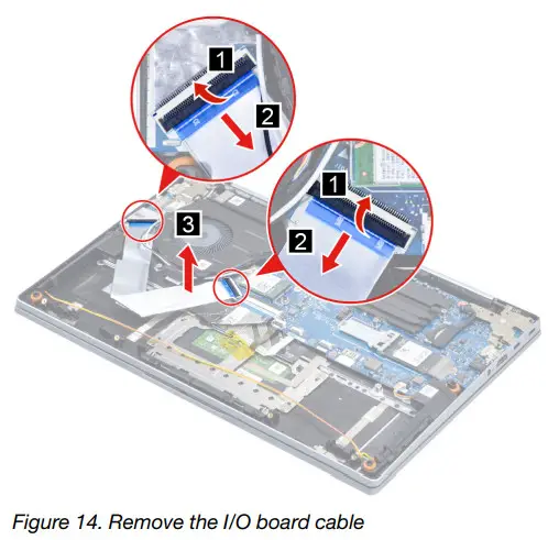
Step 2. Disconnect the fan cable from the system board and release the antenna cables from the cable guide. 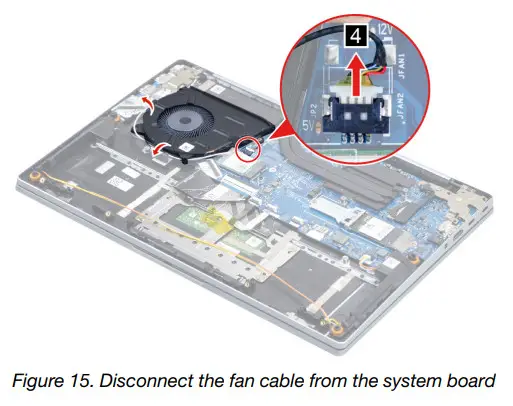
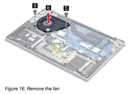
| Screw specifications | Number of screws |
| M2 x L3 | 2 |
Go to https://support.lenovo.com/partslookup to look up the Lenovo part number of the following replacement part: Fan
Remove the speakers
Make sure the following FRU (CRU) has been removed.
“Remove the lowercase” on page 34
“Remove the battery pack” on page 35
Step 1. Disconnect the speaker cable from the system board and then remove the speakers.
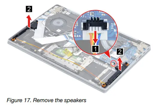
Go to https://support.lenovo.com/partslookup to look up the Lenovo part number of the following replacement part: Speakers
Remove the I/O board
Make sure the following FRUs (or CRUs) have been removed.
“Remove the lower case” on page 34
“Remove the battery pack” on page 35
“Remove the fan” on page 39
Step 1. Remove two screws and then open the hinge. 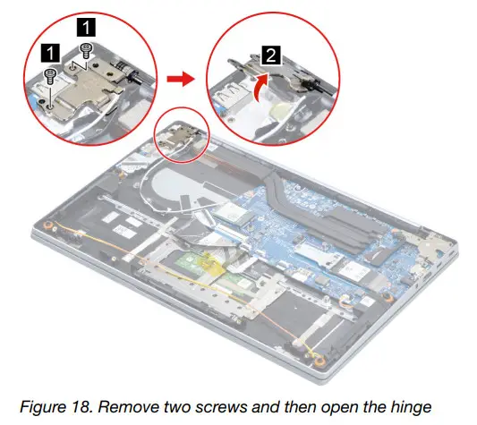
| Screw specifications | Number of screws |
| M2.5 x L5.5 | 2 |
Step 2. Remove one screw and then remove the I/O board.
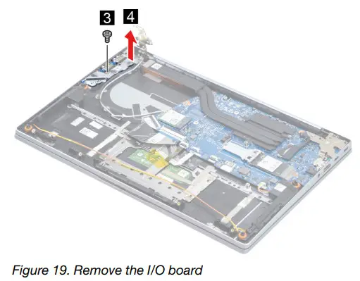
| Screw specifications | Number of screws |
| M2 x L3 | 1 |
Go to https://support.lenovo.com/partslookup to look up the Lenovo part number of the following replacement part: I/O board
Remove the fingerprint board with cable
Make sure the following FRUs (or CRUs) have been removed.
“Remove the lowercase” on page 34
“Remove the battery pack” on page 35
“Remove the fan” on page 39
“Remove the I/O board” on page 40
Step 1. Peel off the tape and then disconnect the fingerprint board cable from the system board. 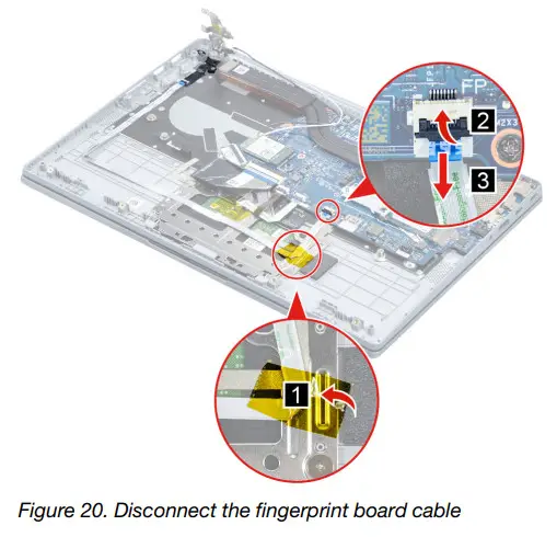
Step 2. Remove two screws and then remove the fingerprint board with a cable.
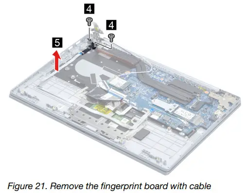
| Screw specifications | Number of screws |
| M1.6 x L2.5 | 2 |
Go to https://support.lenovo.com/partslookup to look up the Lenovo part number of the following replacement part: Fingerprint board with cable
Remove the system board and the I/O board cable
Make sure the following FRUs (or CRUs) have been removed.
“Remove the lowercase” on page 34
“Remove the battery pack” on page 35
“Remove the solid-state drive (SSD) module” on page 36
“Remove the Wi-Fi card” on page 37
“Remove the heat sink” on page 38
“Remove the fan” on page 39
Step 1. Remove two screws and then open the hinge.
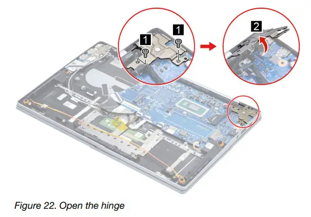
| Screw specifications | Number of screws |
| M2.5 x L5.5 | 2 |
Step 2. Disconnect cables connected to the system board. 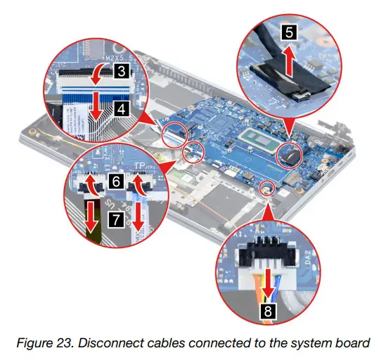
Step 3. Remove four screws and then remove the system board.
| Screw specifications | Number of screws |
| M2 x L3 | 3 |
| M2 x L5.5 | 1 |
Go to https://support.lenovo.com/partslookup to look up the Lenovo part number of the following replacement part: System board
Use a Golden Key U1 tool to flash-write key id information
After replacing the system board and re-assembling the computer, use a pre-made Golden Key U1 tool to start the computer and flash-write the serial number (SN), machine type (MT), product name (PN), and UUID to the new system board.
The Golden Key U1 tool is prepared by running the U1 Update software on a FAT32-formatted USB thumb drive. Go to http://support.lenovo.com/us/en/solutions/HT506954 for detailed instructions on how to create and use a Golden Key U1 tool.
Remove the LCD module
Make sure the following FRU (CRU) has been removed.
“Remove the lower case” on page 34
Step 1. Disconnect the battery pack cable from the system board.
Attention: Use your fingernails to pull the connector to unplug it. Do not pull the cable.
Step 2. Detach the main and auxiliary antenna cable connectors and then disconnect the EDP cable from the system board.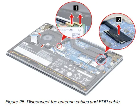
Step 3. Rotate the LCD module to an angle of more than 90 degrees and place the computer on a flat surface as shown. Remove four screws and then remove the LCD module.
| Screw specifications | Number of screws |
| M2.5 x L5.5 | 4 |
Remove the upper case
Make sure the following FRUs (CRUs) have been removed.
“Remove the lowercase” on page 34
“Remove the battery pack” on page 35
“Remove the solid-state drive (SSD) module” on page 36
“Remove the Wi-Fi card” on page 37
“Remove the heat sink” on page 38
“Remove the fan” on page 39
“Remove the speakers” on page 40
“Remove the I/O board” on page 40
“Remove the fingerprint board with cable” on page 42
“Remove the system board and the I/O board cable” on page 43
“Remove the LCD module” on page 45
Go to https://support.lenovo.com/partslookup to look up the Lenovo part number of the following replacement part: Upper case
Disassemble the LCD module
The LCD module as a whole is not an FRU. Instead, it contains FRUs as its components. Before disassembling the LCD module, make sure it has been detached from the upper case.
Remove the hinge cover
Make sure the following FRU (or CRU) has been removed.
“Remove the LCD module” on page 45
Step 1. Remove the hinge cover.
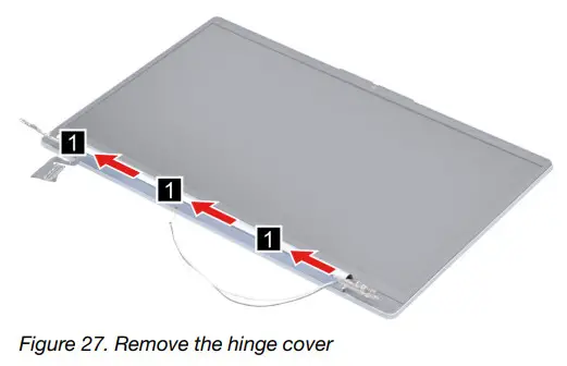
Go to https://support.lenovo.com/partslookup to look up the Lenovo part number of the following replacement part: Hinge cover
Remove the LCD bezel and hinge cover frame
Make sure the following FRUs (or CRUs) have been removed.
“Remove the LCD module” on page 45
“Remove the hinge cover” on page 46
Step 1. Remove three screws and then remove the LCD bezel.
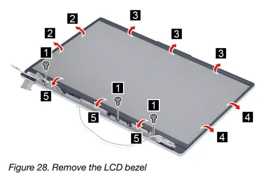
| Screw specifications | Number of screws |
| M1.6 x L4.5 | 3 |
Step 2. Remove the hinge cover frame.  Go to https://support.lenovo.com/partslookup to look up the Lenovo part numbers of the following replacement parts:
LCD bezel
Hinge cover frame
Remove the Hinges
Make sure the following FRUs (CRUs) have been removed.
“Remove the LCD module” on page 45
“Remove the hinge cover” on page 46
“Remove the LCD bezel and hinge cover frame” on page 47
Step 1. Remove six screws and then remove the hinges.
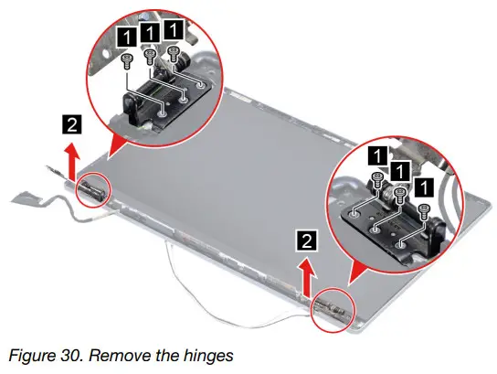
| Screw specifications | Number of screws |
| M2 x L2 | 6 |
Go to https://support.lenovo.com/partslookup to look up the Lenovo part number of the following replacement part: Hinges
Remove the LCD panel
Make sure the following FRUs (CRUs) have been removed.
“Remove the LCD module” on page 45
“Remove the hinge cover” on page 46
“Remove the LCD bezel and hinge cover frame” on page 47
“Remove the Hinges” on page 47
Step 1. Remove the two pieces of removable tape with tweezers.
Note: The removable tape is not reusable. Replace it when replacing related FRUs.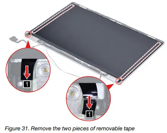
Step 2. Lift the LCD panel carefully and then disconnect the EDP cable from the LCD panel.
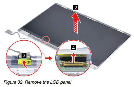
Go to https://support.lenovo.com/partslookup to look up the Lenovo part numbers of the following replacement parts:
LCD panel
Removable tape
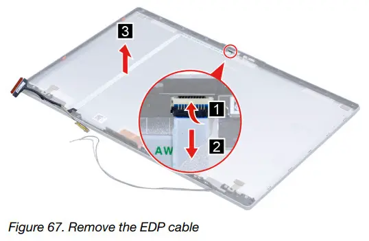
Remove the EDP cable
Make sure the following FRUs (CRUs) have been removed.
“Remove the LCD module” on page 45
“Remove the hinge cover” on page 46
“Remove the LCD bezel and hinge cover frame” on page 47
“Remove the Hinges” on page 47
“Remove the LCD panel” on page 48
Step 1. Disconnect the EDP cable from the camera board and then remove the EDP cable.
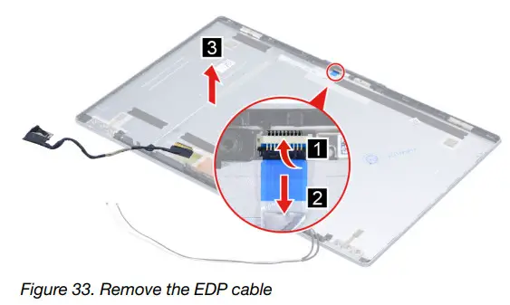
Go to https://support.lenovo.com/partslookup to look up the Lenovo part numbers of the following replacement parts:
EDP cable
Removable tape
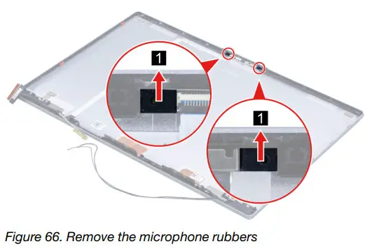
Remove the microphone rubbers
Make sure the following FRUs (CRUs) have been removed.
“Remove the LCD module” on page 45
“Remove the hinge cover” on page 46
“Remove the LCD bezel and hinge cover frame” on page 47
“Remove the Hinges” on page 47
“Remove the LCD panel” on page 48
Step 1. Remove the microphone rubbers. 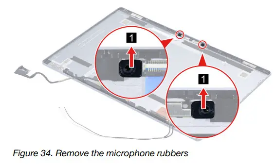
Go to https://support.lenovo.com/partslookup to look up the Lenovo part numbers of the following replacement parts:
Microphone rubbers
Removable tape
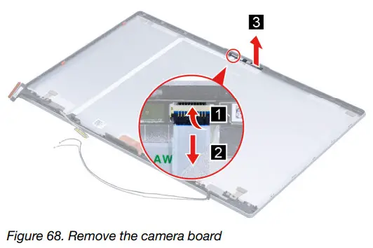
Remove the camera board
Make sure the following FRUs (CRUs) have been removed.
“Remove the LCD module” on page 45
“Remove the hinge cover” on page 46
“Remove the LCD bezel and hinge cover frame” on page 47
“Remove the Hinges” on page 47
“Remove the LCD panel” on page 48
“Remove the microphone rubbers” on page 50
Step 1. Disconnect the EDP cable from the camera board and then remove the camera board.
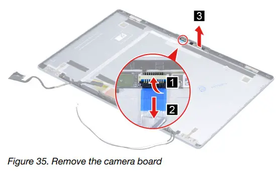
Go to https://support.lenovo.com/partslookup to look up the Lenovo part numbers of the following replacement parts:
Camera board
Removable tape
Remove the LCD cover
Make sure the following FRUs (CRUs) have been removed.
“Remove the LCD module” on page 45
“Remove the hinge cover” on page 46
“Remove the LCD bezel and hinge cover frame” on page 47
“Remove the Hinges” on page 47
“Remove the LCD panel” on page 48
“Remove the microphone rubbers” on page 50
“Remove the EDP cable” on page 49
“Remove the camera board” on page 50
Go to https://support.lenovo.com/partslookup to look up the Lenovo part number of the following replacement part: LCD cover
Removal procedure for 15-inch models
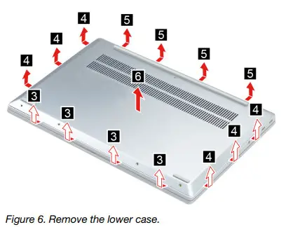
Remove the lowercase
Make sure the computer has been shut down before servicing the computer.
Step 1. Place the computer upside down on a flat surface.
Step 2. Remove nine screws. 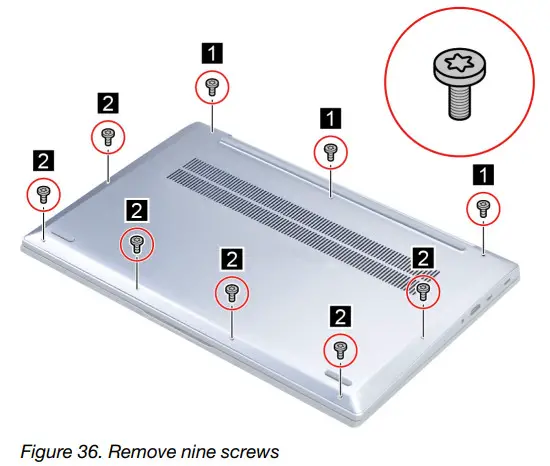
| Screw specifications | Number of screws |
| M2 x L9 | 3 |
| M2 x L3 | 6 |
Step 3. Pry up the latches and then remove the lowercase.
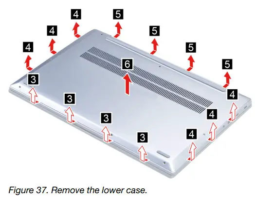
Go to https://support.lenovo.com/partslookup to look up the Lenovo part number of the following replacement part: Lower case
Remove the battery pack
Make sure the following FRU (or CRU) has been removed.
“Remove the lowercase” on page 51
Step 1. Disconnect the battery pack cable from the system board.
Attention: Use your fingernails to pull the connector to unplug it. Do not pull the cable.
Step 2. Remove four screws and then remove the battery pack. 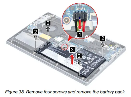
| Screw specifications | Number of screws |
| M2 x L5 | 4 |
Go to https://support.lenovo.com/partslookup to look up the Lenovo part number of the following replacement part: Battery pack
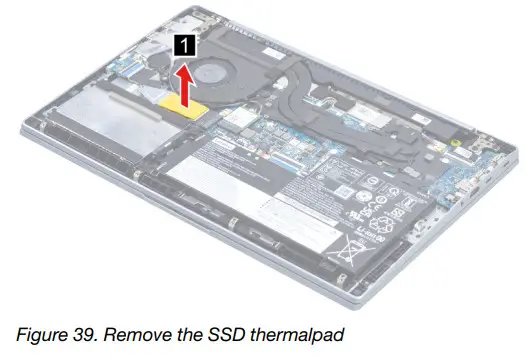
Remove the solid-state drive (SSD) module
Make sure the following FRU (or CRU) has been removed.
“Remove the lowercase” on page 51
Step 1. Disconnect the battery pack cable from the system board.
Attention: Use your fingernails to pull the connector to unplug it. Do not pull the cable.
Step 2. Remove the SSD thermalpad.
Step 3. Remove one screw and then remove the SSD by pulling it away from the slot.
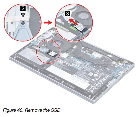
| Screw specifications | Number of screws |
| M2 x L3 | 1 |
Step 4. Remove one screw and then remove the SSD and SSD bracket.
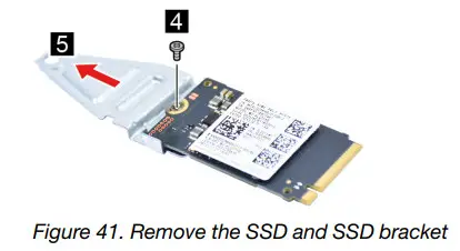
| Screw specifications | Number of screws |
| M2 x L2.5 | 1 |
Go to https://support.lenovo.com/partslookup to look up the Lenovo part numbers of the following replacement parts:
A solid-state drive (SSD)
Solid-state drive (SSD) bracket
Solid-state drive (SSD) thermalpad
Remove the hard disk drive (HDD) module
Make sure the following FRU (or CRU) has been removed.
“Remove the lowercase” on page 51
“Remove the battery pack” on page 52
Step 1. Disconnect the HDD cable from the system board. Remove two screws and then remove the HDD module.
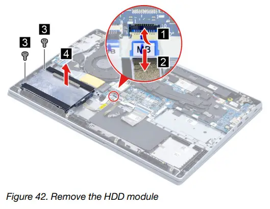
| Screw specifications | Number of screws |
| M2 x L5 | 2 |
Step 2. Remove the HDD cable. 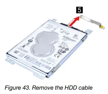
Step 3. Remove four screws and then remove the HDD and HDD bracket.
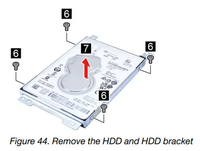
| Screw specifications | Number of screws |
| M3 x L3 | 4 |
Go to https://support.lenovo.com/partslookup to look up the Lenovo part numbers of the following replacement parts:
hard disk drive (HDD)
hard disk drive (HDD) cable
hard disk drive (HDD) bracket
Remove the Wi-Fi card
Make sure the following FRU (or CRU) has been removed.
“Remove the lowercase” on page 51
Step 1. Disconnect the battery pack cable from the system board.
Attention: Use your fingernails to pull the connector to unplug it. Do not pull the cable.
Step 2. Detach the main and auxiliary antenna cable connectors. Remove one screw and then remove the Wi-Fi card by pulling it away from the slot.
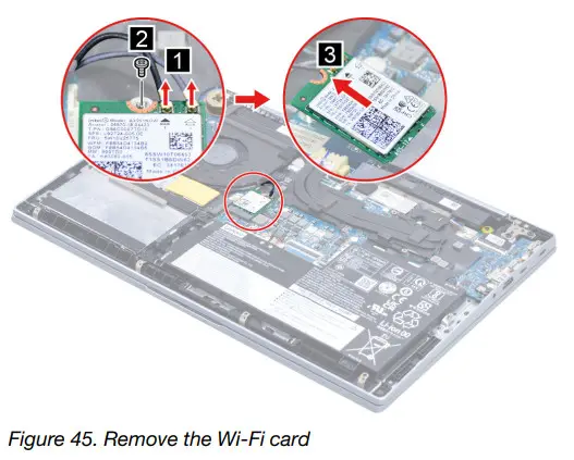
| Screw specifications | Number of screws |
| M2 x L3 | 1 |
Go to https://support.lenovo.com/partslookup to look up the Lenovo part number of the following replacement part: Wi-Fi card
Remove the heat sink
Make sure the following FRU (or CRU) has been removed.
“Remove the lowercase” on page 51
Step 1. Disconnect the battery pack cable from the system board.
Attention: Use your fingernails to pull the connector to unplug it. Do not pull the cable.
Step 2. Loosen five screws and then remove the heat sink.
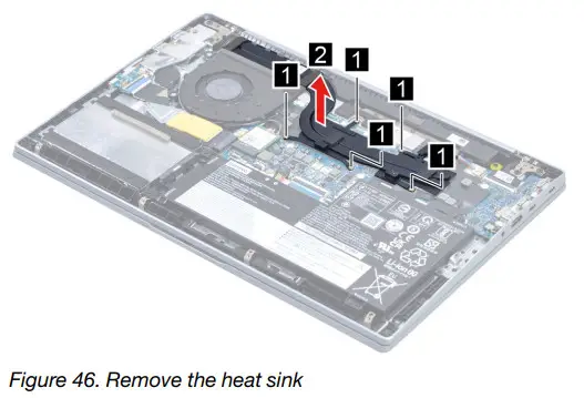
Go to https://support.lenovo.com/partslookup to look up the Lenovo part number of the following replacement part: Heat sink
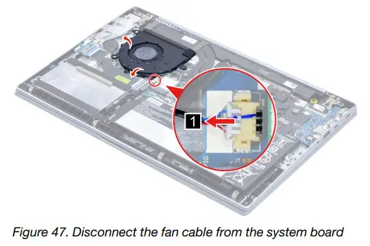
Remove the fan
Make sure the following FRU (or CRU) has been removed.
“Remove the lowercase” on page 51
Step 1. Disconnect the battery pack cable from the system board.
Attention: Use your fingernails to pull the connector to unplug it. Do not pull the cable.
Step 2. Disconnect the fan cable from the system board and release the antenna cables from the cable guide.
Step 3. Remove three screws and then remove the fan.
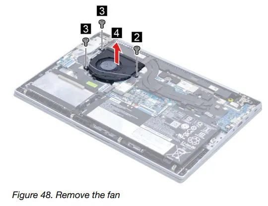
| Screw specifications | Number of screws |
| M2 x L3 | 2 |
| M2 x L5 | 1 |
Go to https://support.lenovo.com/partslookup to look up the Lenovo part number of the following replacement part: Fan
Remove the speaker
Make sure the following FRU (CRU) has been removed.
“Remove the lowercase” on page 51
Step 1. Disconnect the battery pack cable from the system board.
Attention: Use your fingernails to pull the connector to unplug it. Do not pull the cable.
Step 2. Disconnect the speaker cable from the system board and then remove the speaker.
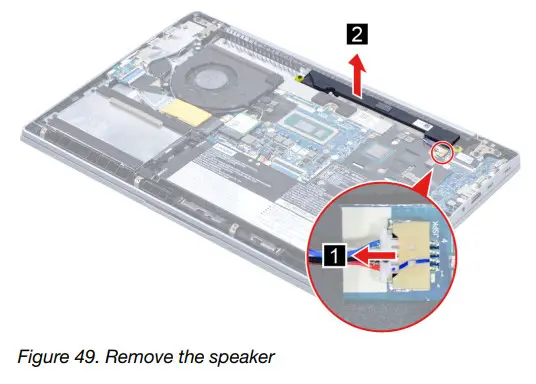
Go to https://support.lenovo.com/partslookup to look up the Lenovo part number of the following replacement part: Speaker
Remove the CMOS battery
Make sure the following FRU (CRU) has been removed.
“Remove the lower case” on page 51
Step 1. Disconnect the battery pack cable from the system board.
Attention: Use your fingernails to pull the connector to unplug it. Do not pull the cable.
Step 2. Disconnect the CMOS battery cable from the I/O board and then remove the CMOS battery.
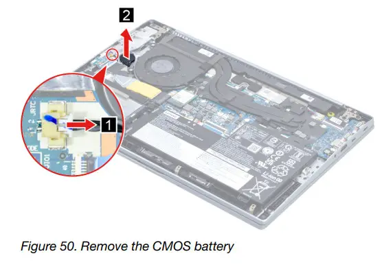
Go to https://support.lenovo.com/partslookup to look up the Lenovo part number of the following replacement part: CMOS battery
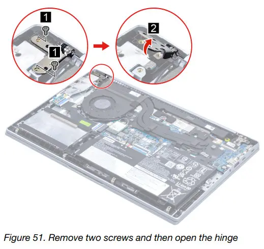
Remove the I/O board and the I/O board cable
Make sure the following FRUs (or CRUs) have been removed.
“Remove the lower case” on page 51
“Remove the CMOS battery” on page 59
Step 1. Remove two screws and then open the hinge.
| Screw specifications | Number of screws |
| M2.5 x L5 | 2 |
Step 2. Disconnect the I/O board cable from the system board. Remove two screws and then remove the I/O board with a cable.
| Screw specifications | Number of screws |
| M2 x L5 | 2 |
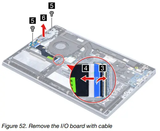
| Screw specifications | Number of screws |
| M2 x L3 | 2 |
Step 3. Separate the I/O board cable from the I/O board.
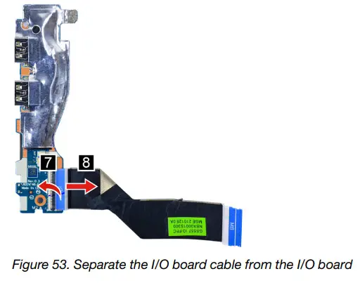
Go to https://support.lenovo.com/partslookup to look up the Lenovo part numbers of the following replacement parts:
I/O board
I/O board cable
Remove the fingerprint board and fingerprint board cable
Make sure the following FRUs (or CRUs) have been removed.
“Remove the lower case” on page 51
“Remove the battery pack” on page 52
“Remove the hard disk drive (HDD) module” on page 54
“Remove the CMOS battery” on page 59
“Remove the I/O board and the I/O board cable” on page 59
Step 1. Remove the fingerprint board cable.
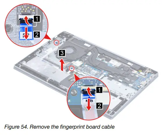
Step 2. Remove the fingerprint board.
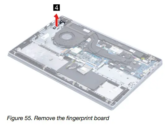
Go to https://support.lenovo.com/partslookup to look up the Lenovo part numbers of the following replacement parts:
Fingerprint board
Fingerprint board cable
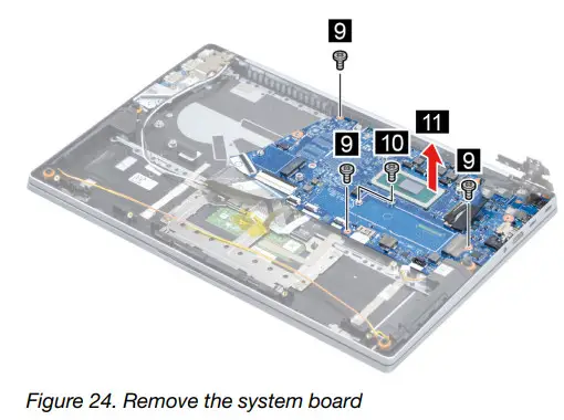
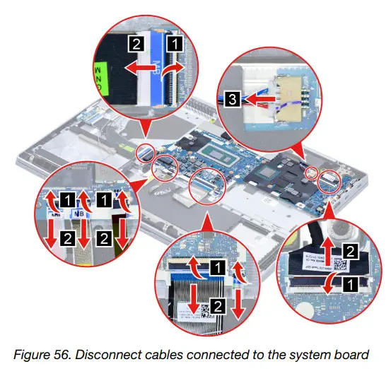
Remove the system board
Make sure the following FRUs (or CRUs) have been removed.
“Remove the lowercase” on page 51
“Remove the battery pack” on page 52
“Remove the solid-state drive (SSD) module” on page 53
“Remove the Wi-Fi card” on page 56
“Remove the heat sink” on page 56
“Remove the fan” on page 57
Step 1. Disconnect cables connected to the system board.
Step 2. Remove six screws and then remove the system board.
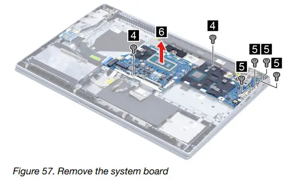
| Screw specifications | Number of screws |
| M2 x L3 | 2 |
| M2 x L3.5 | 4 |
Go to https://support.lenovo.com/partslookup to look up the Lenovo part number of the following replacement part: System board
Use a Golden Key U1 tool to flash-write key id information
After replacing the system board and re-assembling the computer, use a pre-made Golden Key U1 tool to
start the computer and flash-write the serial number (SN), machine type (MT), product name (PN), and UUID
to the new system board.
The Golden Key U1 tool is prepared by running the U1 Update software on a FAT32-formatted USB thumb drive. Go to http://support.lenovo.com/us/en/solutions/HT506954 for detailed instructions on how to create and use a Golden Key U1 tool.
Remove the LCD module
Make sure the following FRU (CRU) has been removed.
“Remove the lowercase” on page 51
Step 1. Disconnect the battery pack cable from the system board.
Attention: Use your fingernails to pull the connector to unplug it. Do not pull the cable.
Step 2. Detach the main and auxiliary antenna cable connectors and then disconnect the EDP cable from the system board.
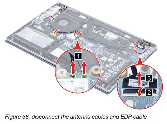
Step 3. Rotate the LCD module to an angle of more than 90 degrees and place the computer on a flat surface as shown. Remove four screws and then remove the LCD module.
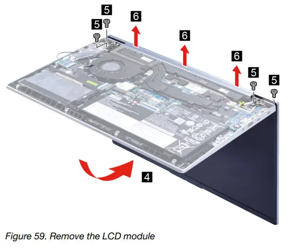
| Screw specifications | Number of screws |
| M2.5 x L5 | 4 |
Remove the uppercase
Make sure the following FRUs (CRUs) have been removed.
“Remove the lowercase” on page 51
“Remove the battery pack” on page 52
“Remove the solid-state drive (SSD) module” on page 53
“Remove the hard disk drive (HDD) module” on page 54
“Remove the Wi-Fi card” on page 56
“Remove the heat sink” on page 56
“Remove the fan” on page 57
“Remove the speaker” on page 58
“Remove the CMOS battery” on page 59
“Remove the I/O board and the I/O board cable” on page 59
“Remove the fingerprint board and fingerprint board cable” on page 61
“Remove the system board” on page 62
“Remove the LCD module” on page 64
Go to https://support.lenovo.com/partslookup to look up the Lenovo part number of the following replacement part:
Disassemble the LCD module
The LCD module as a whole is not an FRU. Instead, it contains FRUs as its components. Before
disassembling the LCD module, make sure it has been detached from the upper case.
Remove the LCD bezel
Make sure the following FRU (or CRU) has been removed.
“Remove the LCD module” on page 64
Step 1. Remove the LCD bezel.
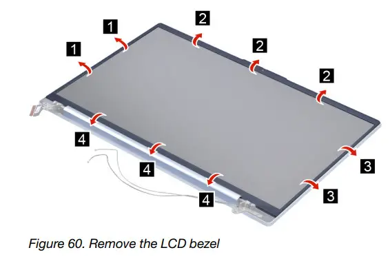
Go to https://support.lenovo.com/partslookup to look up the Lenovo part number of the following replacement part:
LCD bezel
Remove the strip cover
Make sure the following FRU (or CRU) has been removed.
“Remove the LCD module” on page 64
“Remove the LCD bezel” on page 65
Step 1. Remove the strip cover. 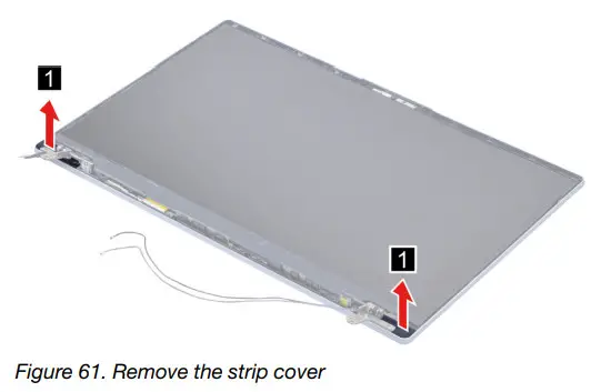
Go to https://support.lenovo.com/partslookup to look up the Lenovo part number of the following replacement part: Strip cover
Remove the Hinges
Make sure the following FRUs (CRUs) have been removed.
“Remove the LCD module” on page 64
“Remove the LCD bezel” on page 65
“Remove the strip cover” on page 66
Step 1. Release the cables from the cable guide. 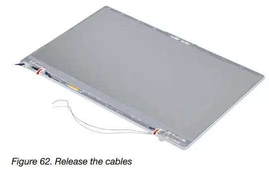
Step 2. Remove six screws and then remove the hinges.
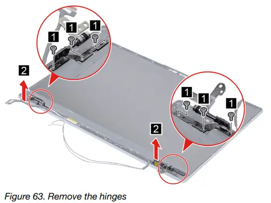
Go to https://support.lenovo.com/partslookup to look up the Lenovo part number of the following replacement part: Hinges
Remove the LCD panel
Make sure the following FRUs (CRUs) have been removed.
“Remove the LCD module” on page 64
“Remove the LCD bezel” on page 65
“Remove the strip cover” on page 66
“Remove the Hinges” on page 66
Step 1. Remove the two pieces of removable tape with tweezers.
Note: The removable tape is not reusable. Replace it when replacing related FRUs.
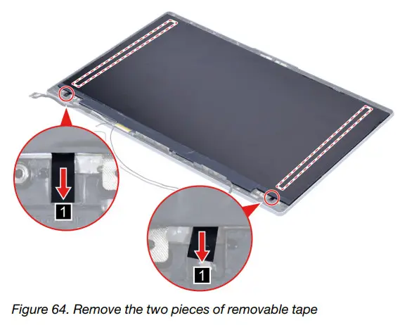
Step 2. Lift the LCD panel carefully and then disconnect the EDP cable from the LCD panel.
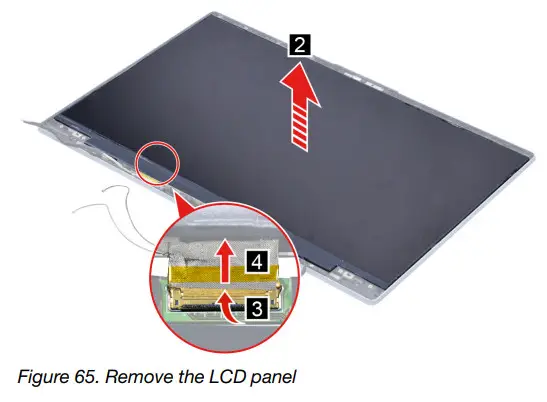
Go to https://support.lenovo.com/partslookup to look up the Lenovo part numbers of the following replacement parts: LCD panel
Removable tape
Remove the microphone rubbers
Make sure the following FRUs (CRUs) have been removed.
“Remove the LCD module” on page 64
“Remove the LCD bezel” on page 65
“Remove the strip cover” on page 66
“Remove the Hinges” on page 66
“Remove the LCD panel” on page 67
Step 1. Remove the microphone rubbers.
Go to https://support.lenovo.com/partslookup to look up the Lenovo part numbers of the following replacement parts: Microphone rubbers
Removable tape
Remove the EDP cable
Make sure the following FRUs (CRUs) have been removed.
“Remove the LCD module” on page 64
“Remove the LCD bezel” on page 65
“Remove the strip cover” on page 66
“Remove the Hinges” on page 66
“Remove the LCD panel” on page 67
Step 1. Disconnect the EDP cable from the camera board and then remove the EDP cable.
Go to https://support.lenovo.com/partslookup to look up the Lenovo part numbers of the following replacement parts:
EDP cable
Removable tape
Remove the camera board
Make sure the following FRUs (CRUs) have been removed.
“Remove the LCD module” on page 64
“Remove the LCD bezel” on page 65
“Remove the strip cover” on page 66
“Remove the Hinges” on page 66
“Remove the LCD panel” on page 67
“Remove the microphone rubbers” on page 68
Step 1. Disconnect the EDP cable from the camera board and then remove the camera board.
Go to https://support.lenovo.com/partslookup to look up the Lenovo part numbers of the following replacement parts:
Camera board
Removable tape
Remove the LCD cover
Make sure the following FRUs (CRUs) have been removed.
“Remove the LCD module” on page 64
“Remove the LCD bezel” on page 65
“Remove the strip cover” on page 66
“Remove the Hinges” on page 66
“Remove the LCD panel” on page 67
“Remove the microphone rubbers” on page 68
“Remove the EDP cable” on page 69
“Remove the camera board” on page 69
Go to https://support.lenovo.com/partslookup to look up the Lenovo part number of the following replacement part: LCD cover
Appendix A. Label locations
IdeaPad 5 14IAL7 and IdeaPad 5 14ABA7
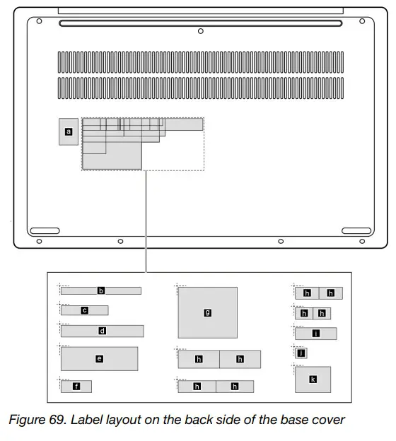
Labels attached to the base cover are country/region specific. Make sure to apply the appropriate labels to the replacement base cover.
Table 10. All base cover labels
| Label | Label name | Applied country/region | Label dimensions |
| a | GML label | 16.077 mm x 22.501 mm | |
| b | Country label | Argentina | 68 mm x 6 mm |
| c | Belarus | 40 mm x 8 mm | |
| d | TW label | 70 mm x 10 mm | |
| e | Adapter label | 65 mm x 20 mm | |
| f | Indonesia rating label | 26 mm x 10 mm | |
| g | KR KCC label | 50 mm x 43 mm | |
| h | WL/BT label | Brazil | 40 mm x 8 mm |
| Israel/US/CA/TW | 30 mm x 30 mm | ||
| South Africa | 70 mm x 10 mm | ||
| Malaysia/Indonesia | 65 mm x 20 mm | ||
| i | Country label | Japan | 35 mm x 10 mm |
IdeaPad 5 15IAL7 and IdeaPad 5 15ABA7
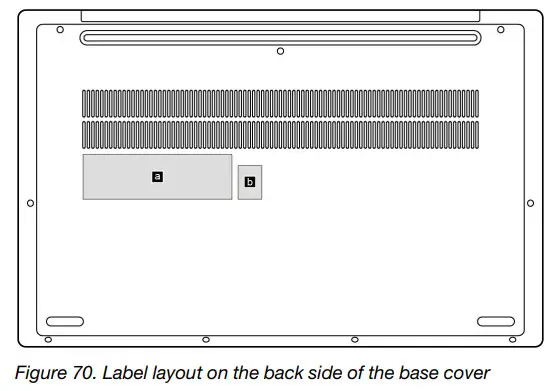
Labels attached to the base cover are country/region specific. Make sure to apply the appropriate labels to the replacement base cover.
Table 11. All base cover labels
| Label | Label name | Applied country/region | Label dimensions |
| a | POD label | 100 mm x 30 mm | |
| b | OS label | 16 mm x 22.5 mm |
Trademarks
LENOVO and the LENOVO logo are trademarks of Lenovo.
All other trademarks are the property of their respective owners. © 2022 Lenovo.
![]()


 Laptop User Guide")


