UOVision UM785-4G LTE Scouting Camera Instruction Manual

1 Camera Overview
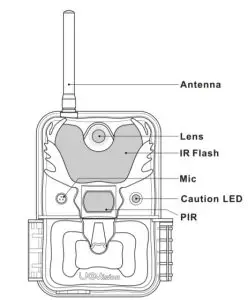
Fig 1 Front View
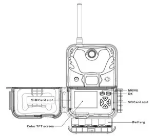
Fig 2 Operation Interface
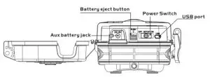
2 Set power
To supply power for the camera, 4, 8 or 12 size AA batteries are needed.
Notice :
- Do not mix different types of batteries
- Please do not mix the old batteries with the new batteries
- Recommend high-density and high-performance batteries, such as Alkaline or Lithium batteries.
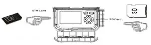
3 Installing your SIM card and SD card
Notice:
- This product support B1/B3/B5/B7/B8/B20@FDD LTE B38/B40/B41@TDD LTE B1/B5/B8@WCDMA B3/B8@GSM. Be sure that the PIN Code of the SIM card is disabled
- The maximum support SD memory is 32G
4 Customizing camera settings
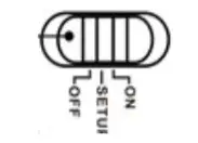
Fig 5 Power Switch
- OFF: power off;
- SETUP: setting the CAM;
- ON: working mode (the screen will power off).
Toggle the power switch to SETUP. You will see the screen shown below.
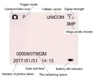
Fig 6 Main Screen
Press the MENU button. Use▲▼◄ ► buttons for navigation.
►button in the preview can also be directly manual photo. OK button to confirm operation/playback.
4.2 Setting maps
| NET | |
| Send Mode | Off/Instant |
| Remote Control | Real Time/Delay 0.5H/1H/2H/3H/4H/6H/12H/24H |
| FW Download | ~ |
Note:
Send Mode:
Off: disable the transmission function.Instant: enable the instant transmission. Max Number of Instant means the number of photos that is allowed to send out per day. If you want to control your data flow, set the maximum number. The number 00 means infinity. Remote Control: You can remote control your camera via mobile phone or web-portal. Choose Real Time, the wireless module is keeping work so the power consumption is huge. Delay 24H means the wireless module will wake up at least one time in 24 hours.
| CAM | ||
| Camera Mode | Photo | Custom Settings |
| Video | Video Size: WVGA/720P/1080P Video Length: 5s-60s(Default:10s) | |
| Custom Settings | Photo Size | 3M/8M/10M/12M |
| Flash Power | Low/High | |
| Photo Burst | 1~10 | |
| Burst Speed(Fast/Slow) | ||
| Sending Option | ||
| Shutter Speed | Normal/Fast | |
Photo Burst:It’s the taken number of pictures when a triggering. If photo burst is 3, it means the camera will take 3 pictures after one triggering. You also can choose which one of the pictures will be sent via Send Option.
Shutter Speed:Normal is suitable for most application scenarios. Fast can be used to reduce motion blur.
| PIR | |
| Trigger Mode | PIR Trigger/Time Lapse/Both |
| PIR Sensitivity | Low/Auto/High |
| PIR Interval | 5s-60min(default:30s) |
| Time Lapse Interval | 3min~24hours (default:24Hours) |
| Work-Time (4 groups) | Default:Off |
PIR Interval:It means how often the PIR sensor can be allowed to work. This prevents the card from filling up with too many redundant images.
Time Lapse:When choose time lapse, camera takes photos or videos even when it is not triggered by a nearby live animal. It’s useful for constant monitoring of an area.
Work Time:The camera can work at a preset time and preset days. In the rest of the time the camera is not work. Work hour: 00:00-00:00 means 24 hours. If the settings is cross the day, for example: Start: 20:00 Stop: 10:00 means 00:00-10:00 am and 20:00-24:00 of the chosen day.
| SYS | |
| Set Clock | Enter to set date and time |
| Language | Ten languages |
| Password | Off/On |
| Rename | Off/On |
| Overwrite | Off/On |
| Upload Settings | ~ |
| Download Settings | ~ |
| Format SD Card | Format SD Card |
| Default | Restore all customer settings to default values |
| Software Version | Software version information |
Password:Make sure you write down your password or save it to your mobile phone so you can access your camera if you ever forget your password.
4.3 Send a test photo
- Switch camera to Setup mode, press ► button to take a picture, then press OK button to check this picture;
- Press the MENU button, choose send. You will see sending progress shows on the LCD screen.


Fig 7 Fig 8
Once you see send successful, check your email account or phone see if you receive the correct photo. If the sending is failure, choose Diagnose to generate a Log file and the FAQ will help you with your. Log file.
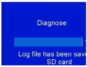
Fig 9 Fig 10
5 Connecting CAM to cloud server
5.1 Connecting CAM to cloud server
Open your browser and access the address:
https://www.linckeazi.com/index.html
Click ‘Sign up’ on the page to pop up the registration page.
The registered users of the platform need to fill in the user name, email address, email verification code, setup password, verification password (re-enter the setup password), and then agree to the terms and agreements to complete the platform registration.
If you have registered for the cloud platform, enter your account and password to log in directly.
.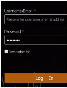
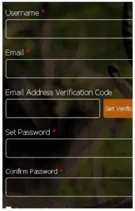
Fig 11 Fig 12
Click ‘Add Device’, a form will pop out requesting basic information for your CAM.
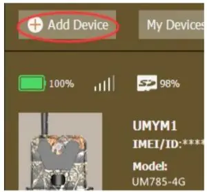
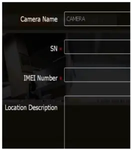
Fig 13 Fig 14
Name your CAM, and add location description if necessary, the SN and IMEI can be found labeled inside CAM:
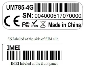
Fig 15
5.2 Send a photo to cloud server
Choose a picture, press MENU, Select ‘send’, the process of sending photo will present at screen, and within minutes your cloud account will receive your photo.
If you have the E-mail transfer function enabled on your Linckeazi cloud platform, the cloud platform will also send a photo or video copy to your E-mail address.

Fig 16
If the above test has accomplished, then you can slide power switch to ‘on’ and start using it take photo or video automatically.
6 Setting CAM with Web Portal or APP
The CAM can be set up conveniently with cloud server and APP as well.
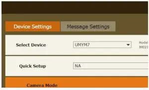
Fig 17
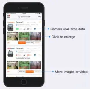
As to APP, Please search“Linckeazi” in Google play(or scan the QR code) and install the APK file to your smart phone.

The adding and setting process is quite similar to cloud server.
LinckEazi APP Function Introduction
7 Mount tips
Use cable or belt cross the holes or slits, tie it up at trees or anywhere you want to mount.
Mount the camera approximately 1.4m off the ground facing straight forward as level as possible. For instance, place the camera 7m-10m from a field edge facing the woods. For the inside of timber, positioning the camera facing a thicket approximately 7m-10m away.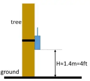
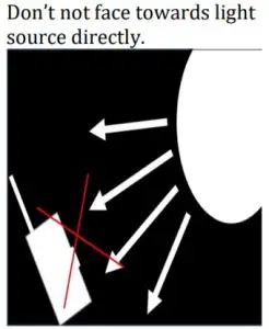
Fig 20
Use the forest for reflection, add more light to your target.
Fig 21
Appendix Ⅰ: Technical Specifications
| Picture Resolution | 12MP, 10MP, 8MP(Interpolated), 3MP |
| Lens | F/NO=2.2 FOV(Field of View)=58° (FOV10m=7.72meter) |
| Frequency Bands | FDD-LTE: B1/B3/B5/B7/B8/B20;TDD-LTE:B38/ B40/B41;WCDMA: B1/B5/B8; GSM: 900/1800 |
| IR-Flash | 6m, 12m |
| Display Screen | 2.4” LCD |
| Memory Card | Up to 32GB |
| Video Resolution | WVGA,720P,1080P |
| PIR Sensor | Multi Zone |
| PIR Sensitivity | Adjustable (High/Normal/Low) |
| Trigger Time | 0.6s |
| Operation/Storage Tem. | -30 – +60°C / -40 – +80°C |
| Trigger Interval | 0s – 60 min. |
|
Time lapse | 3,4,5-55 min (in 5 min increments); 1-8 hours(in 1 hour increments); 12 hours/16 hours/20 hours/24 hours |
| Photo Burst | 1–10 |
| Video Length | 5–60s |
| Power Supply | 4×AA, 8×AA or 12AA |
| Stand-by Current | < 0.25 mA (<6mAh/Day) |
| Low Battery Alert | LED Indicator; SMS alert |
| Mounting | Rope/Belt/Python lock |
| Dimensions | 166 x111 x65 mm |
| Operation Humidity | 5% – 90% |
| Security authentication | FCC, CE, RoHS |
Appendix Ⅱ: Parts List
| Part Name | Quantity |
| Digital Camera | One |
| Belt | One |
| User Manual | One |
| Quick Start | One |
| Antenna | One |
Declaration of Conformity to Directive 2014/53/EU
CE Caution:
Hereby, the manufacturer declares that this camera is in compliance with the essential requirements and other relevant provisions of Directive 2014/53/EU. Pls ask for your distributor for a copy of the Declaration of Conformity to Directive 2014/53/EU.
The camera manufacturer provides 12 months of warranty service for this product against manufacturing defects or malfunctions. If your camera fails to function under normal use within 1 years, the camera manufacturer will repair or replace the camera at no charge. The purchase receipt must be included from an
authorized retailer to validate the warranty. Improper use of the camera resulting in damage is not covered by this warranty.
The camera manufacturer can provide repair service, after the warranty expiration. The customer will be responsible for any charges on parts, labor and shipping costs. Please contact the manufacturer for more details. Please contact the area dealer for more details.


