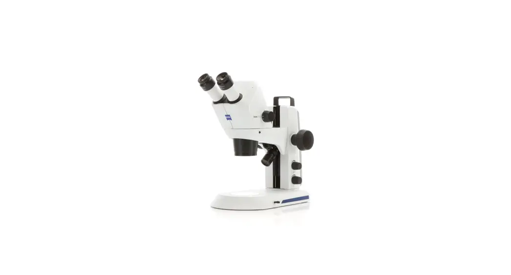
![]() Stemi 305 Stereo Microscope
Stemi 305 Stereo Microscope
User Manual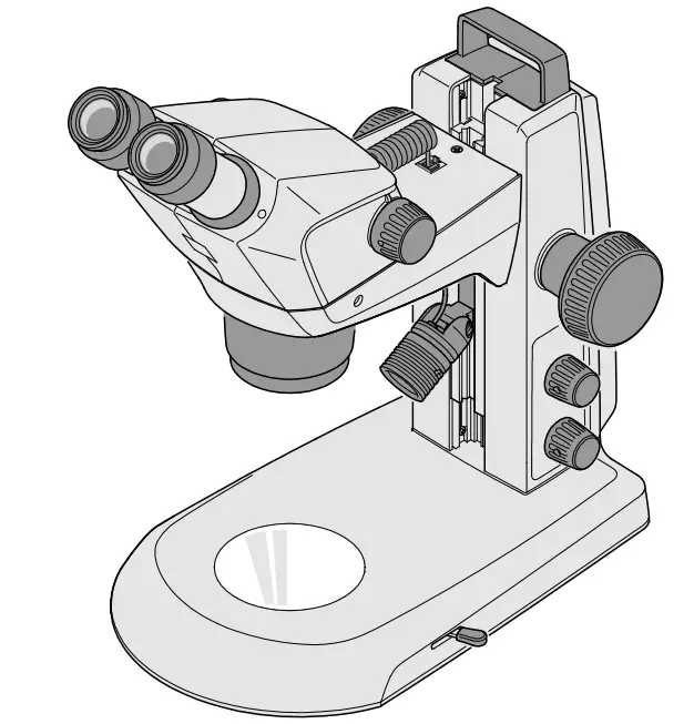
Knowledge of this manual is required for the operation of the instrument. Would you therefore please make yourself familiar with the contents of this manual and pay special attention to hints concerning safe operation of the instrument.
The specifications are subject to change; the manual is not covered by an update service. Unless expressly authorized, forwarding and duplication of this document, as well as utilization and communication of its contents are not permitted.
Violations will entail an obligation to pay compensation. All rights reserved in the event of granting of patents or registration of a utility model.
INTRODUCTION
1.1 General information
The stereo microscope Stemi 305 has been designed, produced and tested in compliance with the standards DIN EN 61010-1 (IEC 61010-1) and IEC 61010-2-101 “Safety Requirements for Electrical Measuring, Control and Laboratory Equipment”.
The device meets the requirements of the EC Directive 98/79/EC regarding ivd products and the EC RoHS Directive 2011/65/EU and carries the mark.
This operating manual contains information and warnings to be observed by the operator.
The devices must be disposed of in compliance with the WEEE Directive 2012/19/EU.
In this operating manual, the following warning and information symbols are used:
| CAUTION This symbol indicates a possible hazard to the user. | |
 | CAUTION LED risk group 2 acc. to DIN EN 62471:2009 Optical radiation is emitted. Do not look into the beam. This may damage your eyes. |
 | CAUTION: High-energy UV radiation! Risk of damage to eyes and skin! |
 | CAUTION Hot surface! |
 | CAUTION Remove the power plug before any intervention in the instrument! |
 | ATTENTION This symbol indicates a possible hazard to the instrument or system. |
| NOTICE This symbol indicates information which deserves special attention. |
1.2 Notes on instrument safety
| If it becomes apparent that the safety measures are no longer effective, the device must be taken out of service and secured against being used again unintentionally. Please contact a ZEISS service agency or the Carl Zeiss Microscopy Service to have the instrument repaired. | |
| Do not operate the devices included in the scope of supplies in a potentially explosive atmosphere, in the presence of volatile anaesthetics or flammable solvents such as alcohol, gasoline or similar substances. | |
| The devices may only be operated by instructed persons who have been informed about the possible risks in conjunction with the use of microscopes and the fields of application in question. The microscope is a high-precision device that may be impaired in its performance or even destroyed if handled improperly. |
| Before commissioning the instrument, make sure that the existing power supply is suitable for the instrument. |
| Make sure that the mains plug is removed from the socket before the instrument is opened. |
| The devices are not equipped with special equipment protecting them from corrosive, potentially infectious, toxic and radioactive or other samples that may be hazardous to health. If you handle such samples, be sure to observe all legal requirements, in particular the relevant national accident prevention regulations. |
| The devices are not equipped with special equipment protecting them from corrosive, potentially infectious, toxic and radioactive or other samples that may be hazardous to health. If you handle such samples, be sure to observe all legal requirements, in particular the relevant national accident prevention regulations. |
| The LED reflected-light illuminators and the LED transmitted-light illuminators have been classified as belonging to LED risk group 2 acc. to DIN EN 62471:2009. Avoid looking directly into the LED light. | |
| If the device is operated with an external cold light source (high-energy light), never look directly into the fibre optic output of the cold light source. Otherwise, there is a risk of dazzling and blindness. |
| Never cover the open light guide socket or the fibre optic output. There is a fire hazard! In all cases avoid covering the open light guide socket or the fibre optic output with your hand or other parts of your body. There is a risk of burns! |
Notes on instrument safety
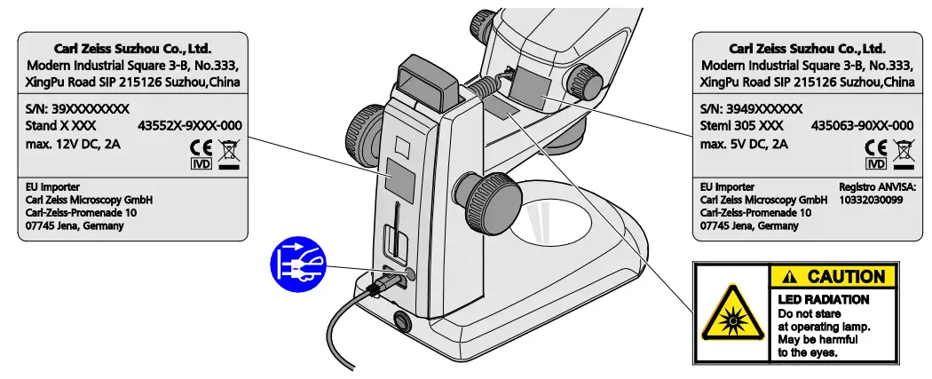 Fig. 1 Warning and information labels on the device
 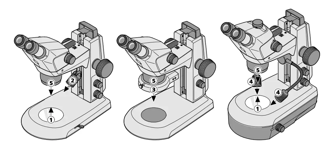 Fig. 2 Warning labels and apertures for LED radiation
- LED aperture, transmitted-light illuminators
- LED aperture, spot illuminator K LED
- LED aperture, ring illuminator K LED, segmentable
- LED aperture, double spot illuminator K LED
- LED aperture, integrated vertical illuminator
1.3 Warranty notes
The manufacturer guarantees that the device is free from material or manufacturing defects when delivered. Any defects which may have occurred must be reported to us immediately and steps be taken to minimize damage. If notified of such a defect, the device manufacturer is obligated to rectify it at his discretion, either by repairing the instrument or by delivering an intact replacement. No guarantee is provided for defects caused by natural wear (wearing parts in particular) and improper use.
The instrument manufacturer shall not be liable for damage caused by faulty operation, negligence or any other tampering with the device, particularly the removal or replacement of instrument components, or the use of accessories from other manufacturers. Such actions will render all warranty claims invalid.
No maintenance or repair work may be performed on the microscopes which exceed the activities specified in this operating manual. Repair may only be performed by ZEISS Service or by persons specifically authorized by it. Should any malfunctions occur on the device, please first contact the Carl Zeiss Microscopy Service or, abroad, the ZEISS representative in your area.
DESCRIPTION
2.1 Indication for use
The stereo microscopes Stemi 305 are microscopes for magnifying spatial observation of small objects.
They have been designed and built for training purposes in schools, universities and natural science facilities. They are used, moreover, in biological and medical laboratories, in industrial manufacture and quality assurance.
Stemi 305 is envisaged for applications in biology and in medicine for the analysis of blood and/or tissue samples from the human body. Applications in the field of diagnostic medicine are explicitly excluded, except for the field of medical research.
2.2 Microscope system
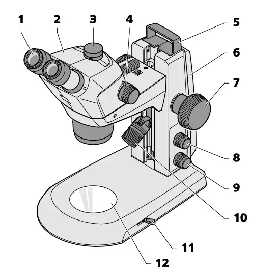 Fig. 3 Microscope system Stemi 305
- Eyepiece in eyepiece tube (eyepiece 10x/23)
- Microscope body (trinocular) with installed vertical illuminator
- Interface for cameras with C-mount connector
- Zoom button to adjust the magnification
- Handle
- Stand (model K EDU)
- Focusing drive to focus the specimen
- Rotary/push-button for switching ON and OFF the illuminators or the additional reflected-light illumination and for adjusting the illumination intensity
- Rotary/push-button for switching ON and OFF the transmitted-light illumination and for adjusting the illumination intensity
- Reflected-light illumination (spot illuminator K LED)
- Lever for adjusting the transmitted-light illuminator – bright field or dark field on the stand K EDU
- Insert plate for placing the specimen
![]() The illustrated microscope equipment shows an example and may differ from the ones actually existing!
The illustrated microscope equipment shows an example and may differ from the ones actually existing!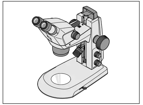 Fig. 4 Stemi 305 EDU microscope set
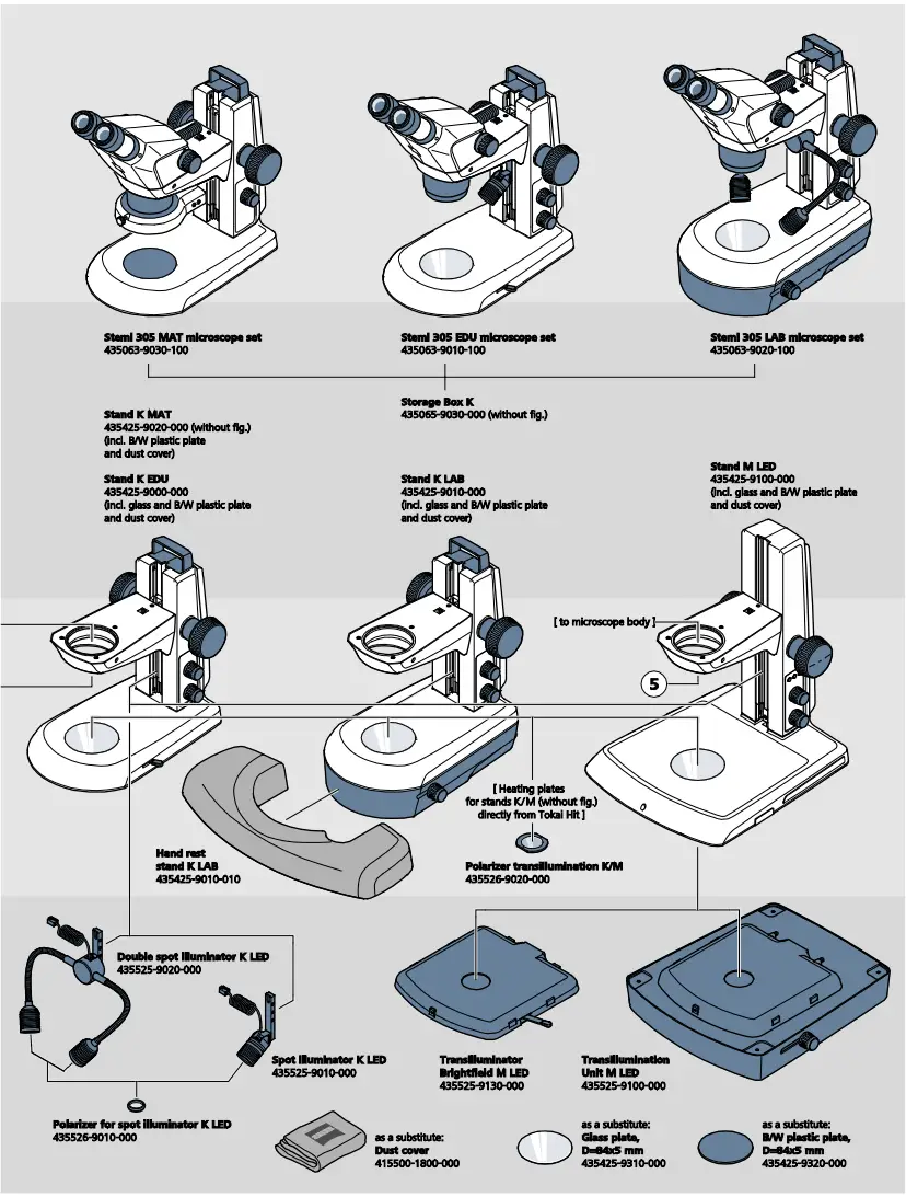
2.3 Microscope sets and fields of application
Stemi 305 EDU:
- Stemi 305 body in stand K EDU
- integrated controllable vertical illuminator
- reflected-light spot illuminator with height and angle adjustment, zoomable
- flat transmitted-light unit for bright and dark field
- for training in tutorial rooms and training institutes
Stemi 305 LAB:
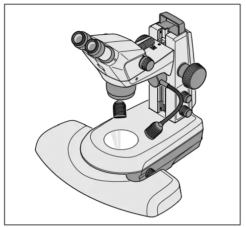 Fig. 5 Stemi 305 LAB microscope set
- Stemi 305 body in stand K LAB
- integrated controllable vertical illuminator
- double spot illuminator with height and angle adjustment
- reflected-light module for bright and dark field and relief contrast
- hand rest (optional)
- for separation and documentation in the laboratory
Stemi 305 MAT:
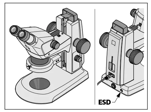 Fig. 6 Stemi 305 MAT microscope set
- Stemi 305 ESD body in stand K MAT
- integrated controllable vertical illuminator
- segmentable ring illuminator for reflected light
- for industrial quality assurance and manufacture
- ESD-capable thanks to its antistatic surface
2.4 Interfaces on the microscope body Stemi 305
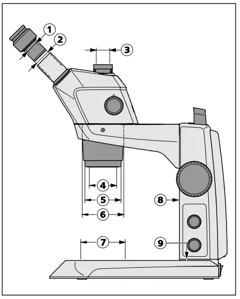 Fig. 7 Interfaces on the Stemi 305 with stand K LED (schematic diagram)
- Optional mount for eyepiece plates ∅ 26 mm
- Eyepiece tube ∅ 30 mm to replace the eyepieces
- Integrated camera adapter 0.5x with C-mount connector for cameras up to 2/3″(only for Stemi 305 trino)
- Internal thread M52x1.0 to accommodate front optics and other accessories
- Mount ∅ 66 mm for ring illuminator
- Mount ∅ 76 mm for microscope body
- Mount ∅ 84 mm for tables, insert plates
- Guide for mounting a reflected-light spot illuminator
- M8 thread to mount retaining arms (only stand K)
Thanks to the interface ∅ 76 mm, the Stemi 305can also be used in conjunction with other stands of the modular kit of the Stereo system – andother ZEISS stereo microscopes such as e.g. theStemi 508, may also be inserted in the stands K.
Front optics, Stemi 305
- External thread M52x1.0 for fastening in the zoom body Stemi 305
- Internal thread M49x0.75 to accommodate optical filters and analyzer for pol.
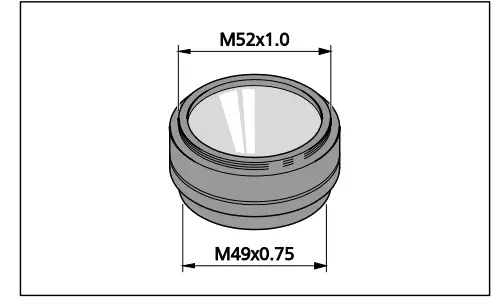 Fig. 8 Front optics, Stemi 305 (example)
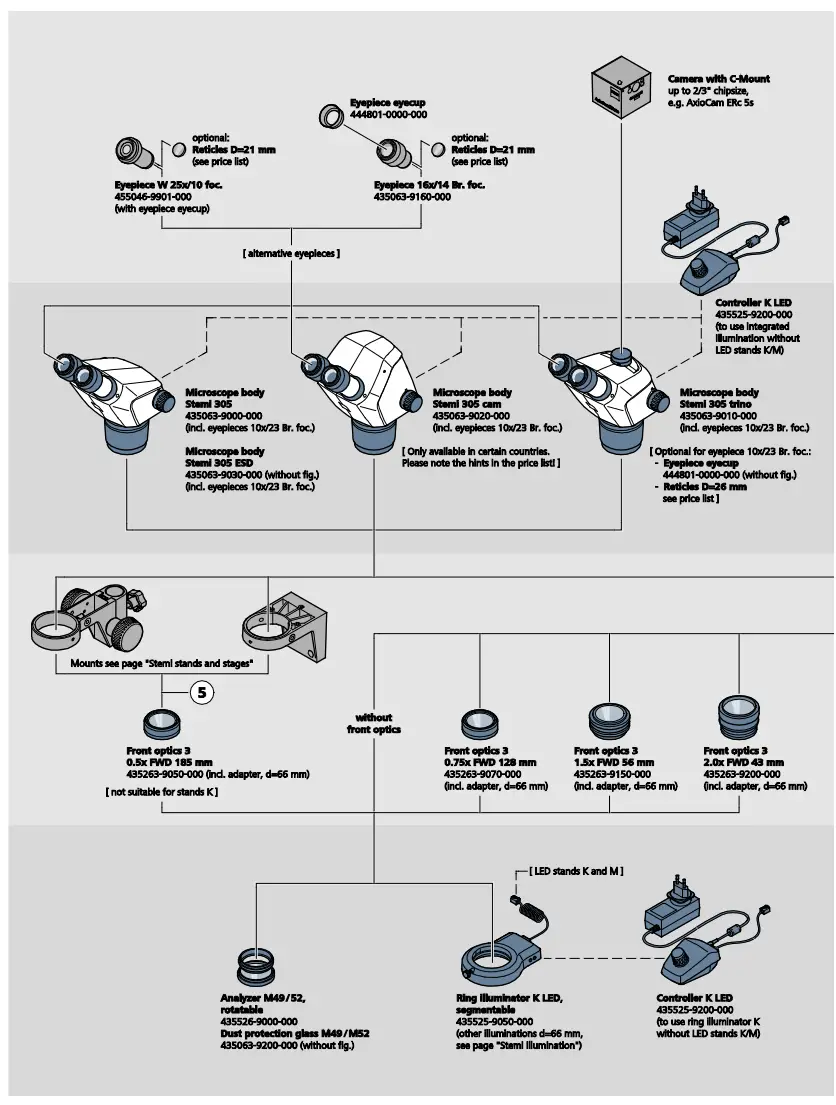
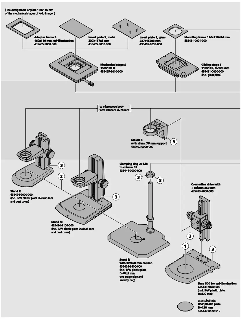
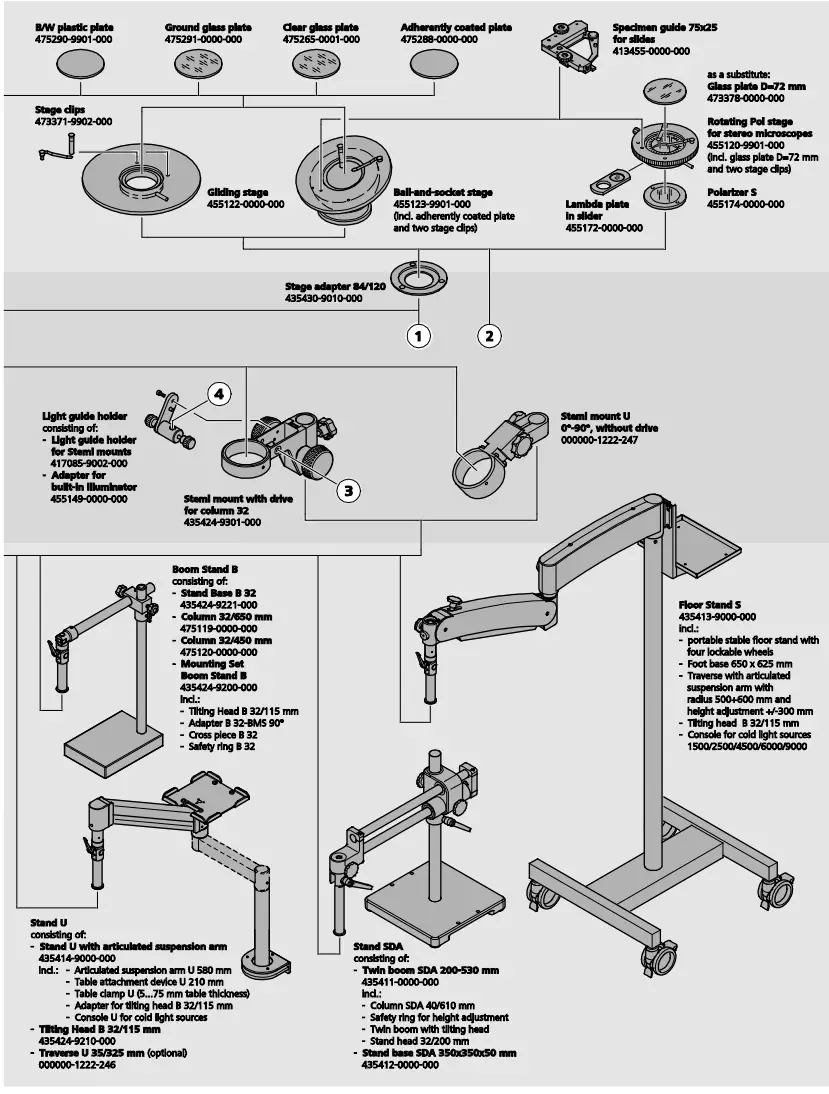
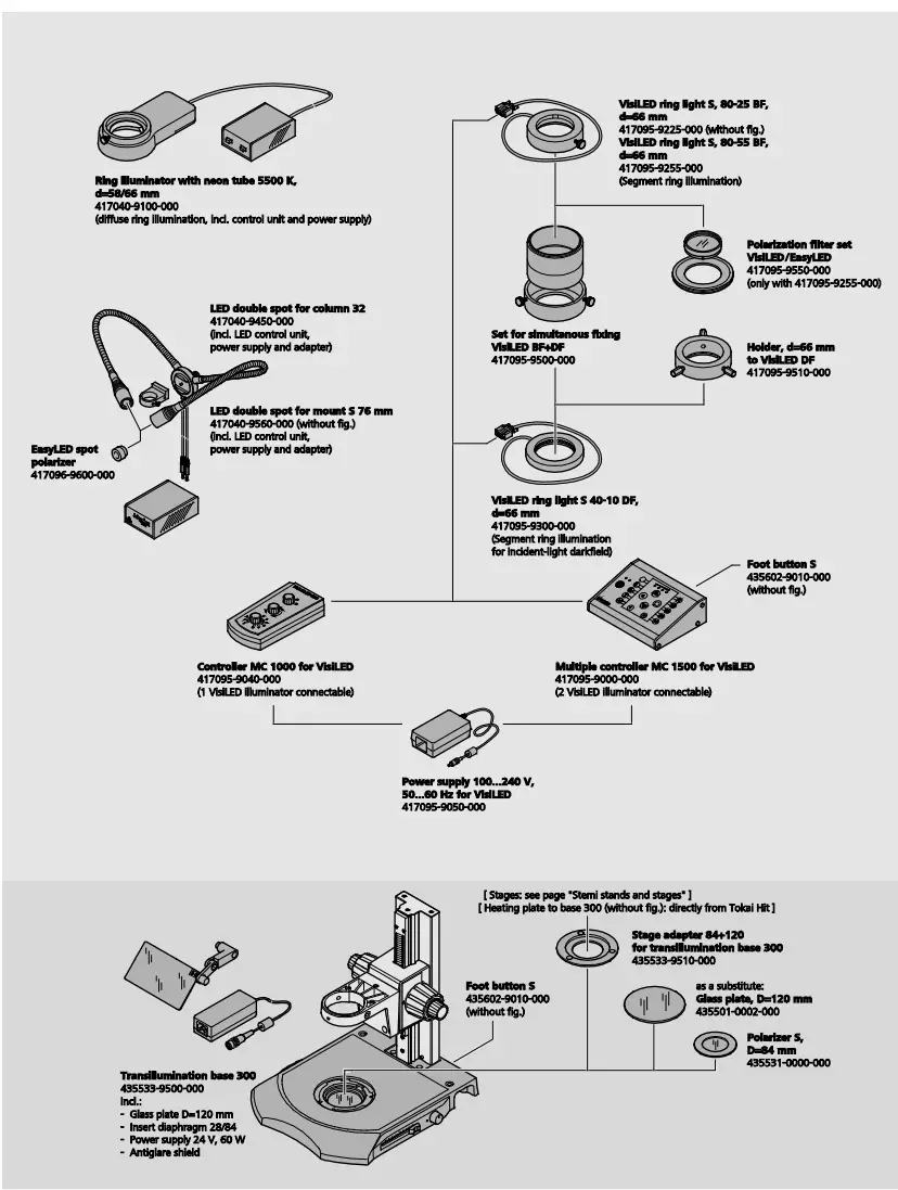
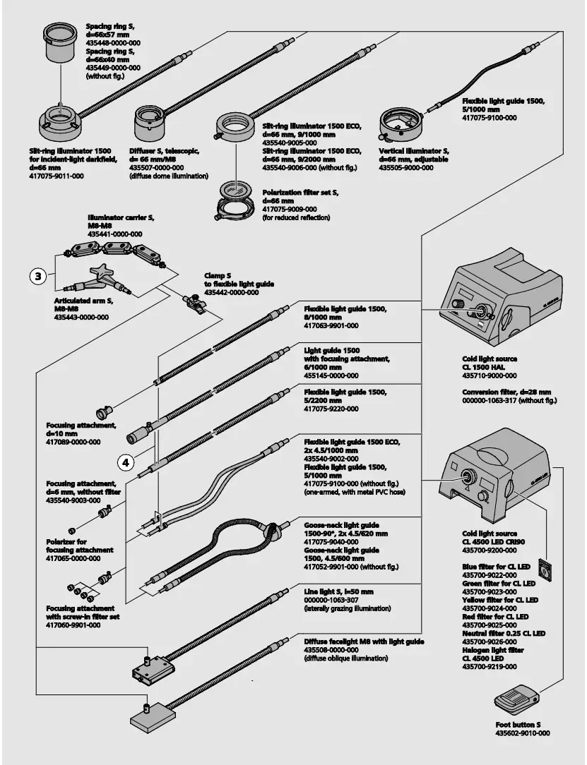
2.5 System overview
2.6 Technical data
Microscope system Stemi 305 EDU
Dimensions 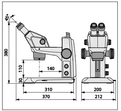
Weight
Stemi 305 in stand K EDU …………………………. 4.6 kg
Microscope system Stemi 305 LAB
Dimensions 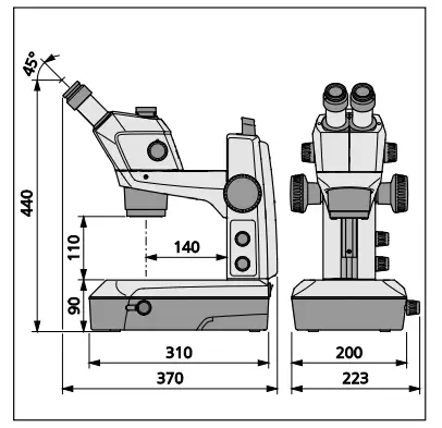
Technical data
Ambient conditions
Ambient conditions
Storage (in packaging)
Admissible ambient temperature ……………………………………. +10 °C to +40 °C
Admissible relative humidity ……………………………….. max. 75 % at +35 °C (non-condensing)
Transport (in packaging)
Admissible ambient temperature …………………………………….. -40 °C to +70 °C
Operation
Admissible ambient temperature ………………………………………. +10 °C to +40 °C
Admissible relative humidity ………………………………………………………… max. 75 %
Atmospheric pressure ……………………………………………………………. 800 hPa to 1060 hPa
Pollution degree …………………………………………………………………………………. 2
Field of application …………………………………………………………………. closed rooms
Height of field of application …………………………………………………………… max. 2000 m
Operating data – desktop power units, microscope and controller K LED
Safety Class …………………………………………………………………… II
Type of enclosure ……………………………………………………………. IP 20
Electrical safety ……………………………………………………………….. acc. to DIN EN 61010-1 (IEC 61010-1)
taking CSA and UL regulations into account
Pollution degree ……………………………………………………………………………….. 2
Overvoltage category …………………………………………………………………. 2
Line voltage …………………………………………………………………………………….. 100 V to 240 V ±10 %
Due to the fact that the instrument features a multi-voltage power supply unit, change-over.
of the device voltage not required!
Line frequency …………………………………………………………………… 50 Hz − 60 Hz
Power consumption: Desktop power unit with connected microscope …………………………….. max. 40 VA
Output desktop power unit for microscope
and for Controller K LED ………………………………………………………………… 12 V DC, max. 2 A
Input desktop power unit for microscope
and for Controller K LED …………………………………………….. 100 V to 240 V, 50 – 60 Hz, max. 0.55 A
Optical risk group classification acc. to DIN EN 62471:2009
Overall device ………………………………………………….. LED risk group 2 acc. to DIN EN 62471:2009
Integrated vertical illumination………………………………… LED risk group 2 acc. to DIN EN 62471:2009
Spot illuminator K LED (reflected illumination) ……………. LED risk group 2 acc. to DIN EN 62471:2009
Double spot illuminator K LED (reflected illumination) …… LED risk group 2 acc. to DIN EN 62471:2009
Transmitted-light unit in stand K LAB ……………………….. LED risk group 2 acc. to DIN EN 62471:2009
Transmitted-light unit in stand K EDU ………………………… LED risk group 2 acc. to DIN EN 62471:2009
LED reflected illumination, peak at 460 nm ………………….. LED risk group 2 acc. to DIN EN 62471:2009
LED transmitted illumination, peak at 465 nm ……………….. LED risk group 2 acc. to DIN EN 62471:2009
INSTALLATION
3.1 General information![]() Before installing and commissioning the device, make sure to read the Notes on instrument safety carefully (see section 1.2, Page 4).
Before installing and commissioning the device, make sure to read the Notes on instrument safety carefully (see section 1.2, Page 4).
The Stemi 305 with the necessary tools and optional equipment is delivered in several standard packages.
- Take all units out of the packaging and check them for completeness according to the delivery note.
 For installation and/or transport of the microscope or the stand, exclusively use the handle (Fig. 3/5) provided to this effect.
 - Remove transport securing devices (adhesive tapes etc.).
- Keep original packaging for a possibly extended period of storage or return of the device to the manufacturer or dispose of it appropriately.
3.2 Installing the stereo microscope
- Place stand on a level, firm support.
- If the Stemi 305 body (Fig. 10/2) has not yet been mounted, insert it in the Stemi mount (Fig. 10/4), align it and secure it using the clamping screw (Fig. 10/6).
The appropriate Allen key (Fig. 10/9) is located in the support on the back of the device. - If the two eyepieces (Fig. 10/1) have not yet been mounted, insert them both to their stop in the eyepiece tube.
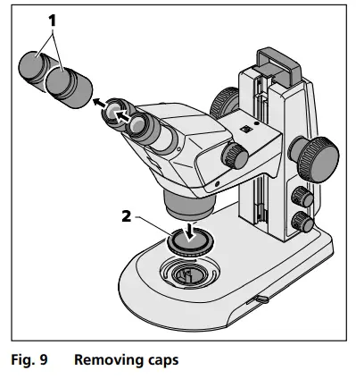
- Remove the two protective caps from the eyepieces (Fig. 9/1) and remove the protective cap (Fig. 9/2) from the objective by turning.
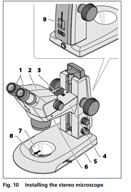
- Insert the connection cable (Fig. 10/3) supplied with the device into the socket on the Stemi body and in the socket on the Stemi mount.
- Insert glass plate or B/W plastic plate (Fig. 10/7) in the mount in the base of the stand.
To this effect, press the glass plate or the B/W plastic plate against the spring (Fig. 10/8) and make it lock in.
Installation of an additional reflectedlight illuminator has been described in section 3.3.1 on page23.
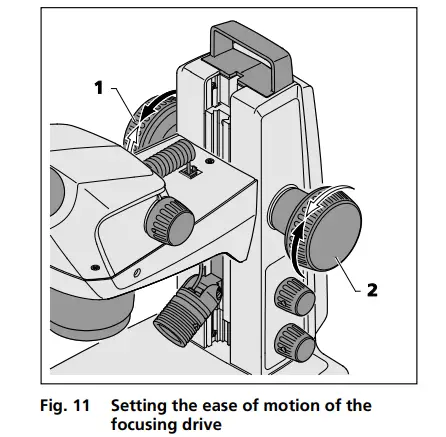
![]() If necessary, the ease of motion of the focusing drive can be set as required on a case-by-case basis by adjusting the two focusing buttons (Fig. 11/1 and 2) in opposite directions.The ease of motion must not be set so loosely that the drive moves downwards by itself. This might damage the microscope or the specimen.
If necessary, the ease of motion of the focusing drive can be set as required on a case-by-case basis by adjusting the two focusing buttons (Fig. 11/1 and 2) in opposite directions.The ease of motion must not be set so loosely that the drive moves downwards by itself. This might damage the microscope or the specimen.
3.3 Mounting optional components
3.3.1 Mounting additional reflected-light illuminator
Various reflected-light illuminators can be used, depending on the case of application.
For fastening, defined interfaces have been provided on the microscope.
3.3.1.1 Mounting spot illuminator K LED or double spot illuminator K LED
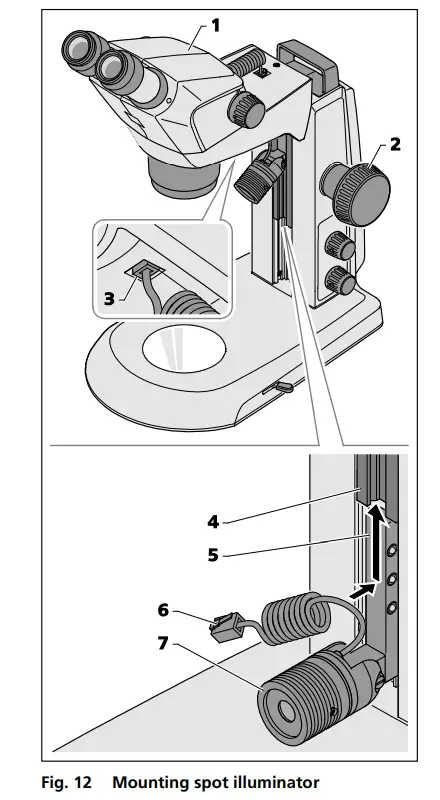
- Move the microscope body (Fig. 12/1) into its uppermost position via the focusing knob (Fig. 12/2).
- Insert the spot illuminator (Fig. 12/7) in the stand by sliding the holder (Fig. 12/5) into the stand guide (Fig. 12/4) from below and push it upwards into the required position.
- Plug the connection cable (Fig. 12/6) of the spot illuminator into the lower socket of the Stemi mount (Fig. 12/3).
The double spot illuminator is mounted in an analogical manner.
3.3.1.2 Mounting ring illuminator K LED (segmentable)
Mounting ring illuminator to microscope body
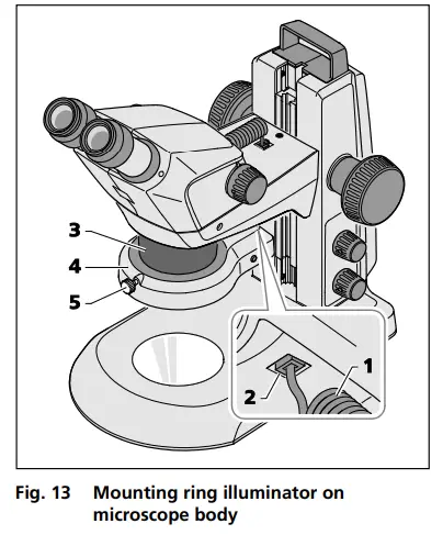
- Insert the connection cable (Fig. 13/1) of the ring illuminator (Fig. 13/4) into the lower socket (Fig. 13/2) of the Stemi mount and into the socket of the ring illuminator.
- Push ring illuminator onto the microscope body (Fig. 13/3) from below, and secure using the knurled screw (Fig. 13/5).
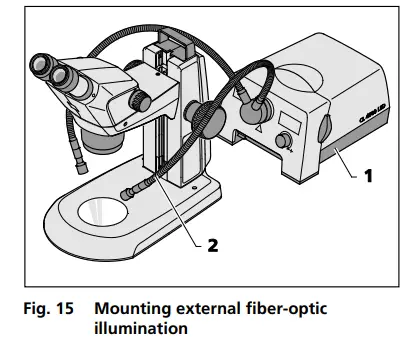
3.3.1.3 External fiber-optic illumination
- Switch on external fiber-optic illumination (Fig. 15/1), adjust illumination intensity and set illumination by bending the two goose necks (Fig. 15/2) so that the specimen is optimally lit.
To this effect, refer also to the separate operating instructions regarding the cold light source.
3.3.1.4 Placing reversible eyepiece cup onto the eyepiece
The eyepieces feature rubber protection rings for spectacles to avoid the spectacles being scratched.
These rings may be replaced at choice by reversible eye cups (Fig. 16/1).
- To this effect remove the protection rings for spectacles (Fig. 16/2) from the eyepieces and position the eye cups (Fig. 16/1).
3.3.1.5 Insert the eyepiece plate into the eyepiece
The adjustable eyepieces are intended for use with eyepiece plates.
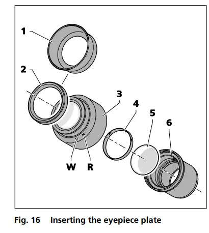
- Unscrew stop (Fig. 16/6) out of the eyepiece (Fig. 16/3).
- Pull locking ring (Fig. 16/4) out.
- Insert eyepiece plate (Fig. 16/5).
- Insert locking ring and re-fasten stop.
If eyepiece plates are inserted by the customer, it must be ensured that the writing is mirror-inverted before insertion into the eyepiece, and true to side after insertion.
![]() Fine cotton gloves should be worn to insert or replace eyepiece plates.
Fine cotton gloves should be worn to insert or replace eyepiece plates.
The slight image offset which is due to the additional glass distance is taken into account on the diopter scale by the zero position not being indicated by the white dot (Fig. 16/W), but by a red dot (Fig. 16/R).![]() Eyepieces with pre-inserted eyepiece plates are available directly from ZEISS.
Eyepieces with pre-inserted eyepiece plates are available directly from ZEISS.
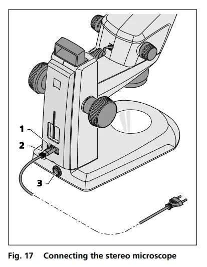
3.4 Connecting stereo microscope to the power supply
- Insert the mains cable (Fig. 17/2) in the mains supply socket (Fig. 17/1) of the stand.
- Connect the mains cable (Fig. 17/2) to a mains supply socket outlet.
3.5 Switching stereo microscope ON or OFF
- Use the power switch (Fig. 17/3) to switch the stereo microscope ON or OFF.
![]() Safe disconnection from the power supply is ensured exclusively by removing the mains plug.The switch on the stereo microscope only switches into standby mode.
Safe disconnection from the power supply is ensured exclusively by removing the mains plug.The switch on the stereo microscope only switches into standby mode.
Do not replace detachable mains cables by inadequately designed mains cables. Only the specified power supply lines may be used.
OPERATION
4.1 Adjusting the stereo microscope
The stereo microscope has been connected and switched ON.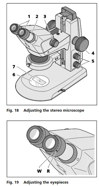
- Place specimen (Fig. 18/7) centrally on the glass or plastic plate (Fig. 18/6) and illuminate it (Fig. 18/5).
The functionality of the knob for the reflected-light illuminator has been described in section 4.2 on page 28. - Set diopter compensation on the adjustable eyepieces (Fig. 18/1) to “0”. “0” on white dot (without eyepiece plate). “0” on red dot (with eyepiece plate), see Fig. 19.
Check that the eyepieces are inserted into the tube to their stop. - Set individual eye distance by shifting the eyepiece tube laterally (Fig. 18/2), until only one complete light circle (specimen field) is visible when looking into the eyepieces with both eyes.
To this effect, a distance of approx. 2 cm must be maintained between the eye and the eyepiece. - Initially, set the zoom (Fig. 18/3) to the smallest magnification.
- Focus on a small distinct detail in the center of the specimen (Fig. 18/4).
- Adjust maximum zoom value (Fig. 18/3). Magnification will probably make the distinct detail appear blurred and no longer in the image center.
- Sharpen the specimen by focusing, then shift the specimen to re-search for the detail and focus “sharply” again (Fig. 18/4).
- Afterwards, reset to the lowest zoom value and correct any image blurring for each eye separately by diopter compensation on the adjustable eyepieces (not on the focusing knob, Fig. 18/4) (compensation of visual defect).
After adjustment of the stereo microscope, the image focus remains unchanged over the entire zoom range.![]() After change of the observer, repeat steps 3. to 8.
After change of the observer, repeat steps 3. to 8.
CARE, MAINTENANCE AND SERVICE
5.1 Care
Care of the devices is restricted to the following operations:![]() The devices are not equipped with special equipment protecting them from corrosive, potentially infectious, toxic and radioactive or other samples that may be hazardous to health. If you handle such samples, be sure to observe all legal requirements, in particular the relevant national accident prevention regulations.
The devices are not equipped with special equipment protecting them from corrosive, potentially infectious, toxic and radioactive or other samples that may be hazardous to health. If you handle such samples, be sure to observe all legal requirements, in particular the relevant national accident prevention regulations.
- Remove contamination in accordance with the national accident prevention regulations.
- Disconnect the devices from the mains power after use. Protect the devices from dust and moisture by using a suitable cover (protective device cover).
- Never expose the devices to inadmissible climate conditions (high humidity and temperature).
 Disconnect the devices from the mains power before cleaning. Make sure, that no cleaning fluids penetrate into the device.
Tenacious impurities on glass surfaces such as fingerprints and traces of grease, are best removed using a cotton wool bud wound around a round wooden stick and very little distilled water or non-aggressive solvent: - Distilled water: Clean glass surface with the slightly moistened cotton wool bud from the center to the edge, using circular movements.
- Cleaning solution for optics, consisting of 15 % isopropanol and 85 % surgical spirit (gasoline): Clean glass surface by the slightly moistened cotton wool bud from the center to the edge, using circular movements.
- Remove dust from optical surfaces using a brush with natural bristles or blow using rubber bellows (air blower).
- Clean plastic parts using commercially available cleaning products (no solvents!).
- Tenacious impurities can be treated carefully with benzine or white spirit.
- All labels on the components and on the desktop power unit may only be cleaned using a dry cotton cloth.
5.2.4 Wearing parts
The following wearing parts can be ordered directly from ZEISS:
| Description | Order No. | Remark |
| Transparent glass plate, d = 84 mm | 435425-9310-000 | |
| Plastic plate B/W, d = 84 mm | 435425-9320-000 | |
| Eyepiece PL 16x/16 Br foc. | 444054-9000-000 | |
| Eyepiece cup | 444801-0000-000 | required 2x |
| Eyepiece 16x/14 Br foc. | 435063-9160-000 | |
| Eyepiece W 25x/10 foc. | 455046-9901-000 | |
| Stemi 305/508 Set of Miscellanea: – lx Allen key, SW 3 – 2x spiral cable RJ 12 – lx cable RJ 12, length lm (for controler K LED) – 2x cover cap for eyepiece – lx cover cap for zoom body Stemi 305 – lx cover cap for c-mount – 2x rubber ring for eyepiece (protection for spectacles) – lx M6 screw for microscope mount of stands K/M – 2x M6 screw for c-mount – lx M4x8 screw for rear panel of stands K/M | 000000-0577-092 | |
| Protective dust cover, stand K | 415500-1800-000 |
5.3 Service
All interventions in mechanical, optical and electronic internal stereo microscope components may only be performed by Carl Zeiss Service or by specifically authorized qualified staff.
To ensure your stereo microscope is optimally set and also operates correctly over an extended period of time, we recommend that you conclude a service/maintenance contract with ZEISS.
For reordering or in case of service, contact your nearest regional ZEISS representative.
5.4 Product disposal
The product was developed, tested and produced in accordance with the valid regulations and guidelines for environmental law of the European Union.
The product and its accessories comply with the EU-regulations 2011/65/EU (RoHS) and 2012/19/EU (WEEE), and the German Electrical and Electronic Equipment Act (ElektroG).
The product contains electronic components which must be disposed of according to the requirements of the 2002/19/EU WEEE Directive and not as domestic waste. In addition, the national regulations must be omplied with.
For details on disposal and recycling please refer to your relevant ZEISS sales or service organization.
APPENDIX
6.1 List of abbreviations
| BF | Bright field |
| B/W | Black/white |
| DIN | Deutsche Industrie-Norm (German Industrial Standard) |
| DF | Dark field |
| EN | Europäische Norm (European Standard) |
| ESD | Electrostatic discharge |
| IEC | International Electrotechnical Commission |
| IP | Internal Protection (Type of enclosure) |
| IvD | In-vitro diagnostics |
| LED | Light Emitting Diode |
| RC | Relief contrast (oblique light) |
| UV | Ultra-violet |
6.2 Troubleshooting
| Description of fault | Cause of error | Troubleshooting |
| Stereo microscope illumination cannot be switched ON. | Power supply interrupted. Power switch not switched ON | Check or establish connection to power supply. Switch power switch on back of stereo microscope ON. |
| Power unit faulty. | Replacing the power unit, see section 5.2 on page 35 | |
| Vertical reflected-light illumination is not lit. | Power supply cable RJ-12 not plugged in. | Insert RJ plug correctly, see section 3.2 or 3.3 on pages 21 and 23 |
| Additional reflected-light illuminators are not lit. | Power supply cable RJ-12 not plugged in. Reflected light not switched ON or dimmed. | Insert RJ plug correctly, see section 3.2 or 3.3 on pages 21 and 23 Press and turn knob Fig. 20/1 several times to switch reflected light ON and to increase its intensity; see section 4.2 on page 28 |
| Transmitted-light illuminator does not light up | Transmitted light not switched ON or dimmed. | Press and turn rotary / push-button Fig. 25/2 to switch illumination ON and to increase its intensity; see section 4.3 on page 32 |
| Transmitted light not connected. | Open stand K EDU or K LAB and connect the plug-in connectors of the LED illumination according to section 5.2.3 on page 37 | |
| Transmitted-light illuminator dirty or control lever cannot be actuated. | Liquids or foreign matter in the transmitted-light unit. | Open and clean stand K EDU or K LAB and eliminate foreign matter according to section 5.2.3 on page 37 |
| Microscope mount moves down by itself. | Focusing drive too easy to move. | Set ease of motion of the focusing drive, see section 3.2 on page 21 |
Should any other faults occur or should you have queries regarding troubleshooting, please contact your regional ZEISS representative.


