DAIKIN Altherma 3 R ECH2O Low Temperature
FIXING PROCESS
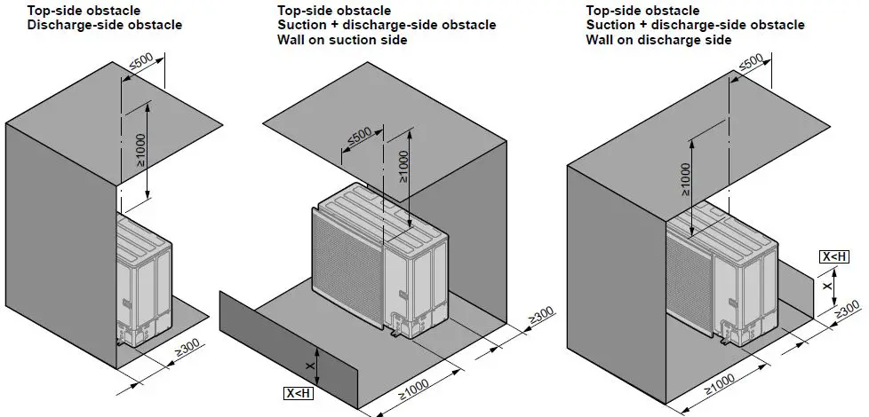
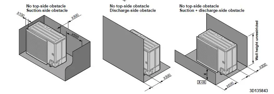
General (mm)
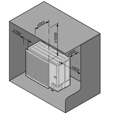
Top side obstacle Suction side obstacle
Specific installer safety instructions
Always observe the following safety instructions and regulations.
CAUTION
To avoid injury, do NOT touch the air inlet or aluminium fins of the unit.
WARNING
Provide adequate measures to prevent that the unit can be used as a shelter by small animals. Small animals that make contact with electrical parts can cause malfunctions,
smoke or fire. Only use R32 as refrigerant. Other substances may cause explosions and accidents. R32 contains fluorinated greenhouse gases. Its global warming potential (GWP) value is 675. Do NOT vent these gases into the atmosphere. When charging refrigerant, ALWAYS use protective gloves and safety glasses.
RISK OF ELECTROCUTION
WARNING
Electrical wiring connection method MUST be in accordance with the instructions from wiring diagram, which is delivered with the unit located at the inside of the service cover. For a translation of its legend.All wiring MUST be performed by an authorised electrician and MUST comply with the applicable legislation. Make electrical connections to the fixed wiring. All components procured on site and all electrical construction MUST comply with the applicable legislation. Rotating fan. Before powering ON the outdoor unit, make sure that the discharge grille covers the fan as protection against a rotating fan If the supply cord is damaged, it MUST be replaced by the manufacturer, its service agent or similarly qualified persons in order to avoid a hazard. ALWAYS use multicore cable for power supply cables.
CAUTION
Do NOT push or place redundant cable length in the unit.
Outdoor unit
To remove the accessories from the outdoor unit
NOTICE
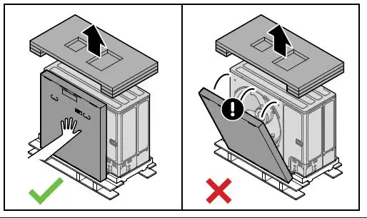
Unpacking
Top packaging. When you remove the top packaging, hold the box containing the discharge grille to prevent it from falling.
Remove the accessories on top and in front of the unit.
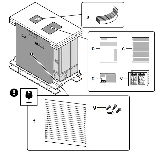
- a Sling to carry the unit
- b Installation Outdoor unit.
- c Multilingual fluorinated greenhouse gases label.
- d Fluorinated greenhouse gases label.
- e Energy labels.
- f Discharge grille.
- g Screws for discharge grille.
To remove the transportation stay
NOTICE
If the unit is operated with the transportation stay attached, abnormal vibration or noise may be generated. The transportation stay protects the unit during transport. During
installation it must be removed.
Prerequisite
Open the service cover
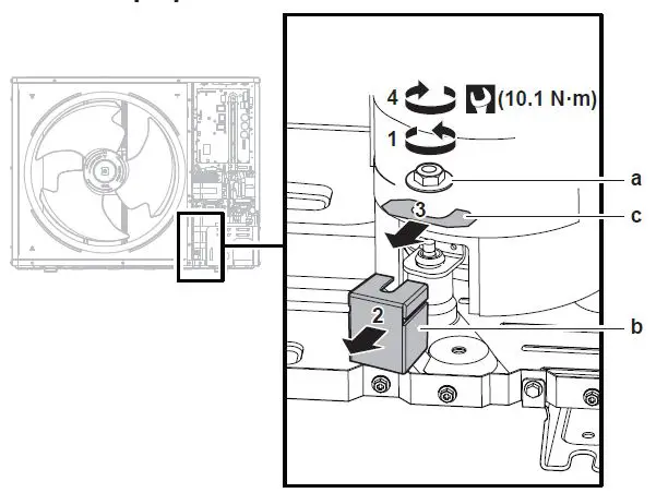
- a Nut
- b Transportation stay
- c Spacer
- Remove the nut (a) of the compressor mounting bolt.
- Remove and discard the transportation stay (b).
- Remove and discard the spacer (c).
- Reinstall the nut (a) of the compressor mounting bolt and torque to 10.1 N.m
Unit installation
Preparing the installation site
Installation site requirements of the outdoor unit
Mind the spacing guidelines on the inside of the front cover.
| English | Translation |
| Discharge side obstacle | Discharge-side obstacle |
| General | General |
| No top-side obstacle | No top-side obstacle |
| Suction + discharge-side obstacle | Suction + discharge side obstacle |
| Suction-side obstacle | Suction side obstacle |
| Top side obstacle | Top-side obstacle |
| Wall height unrestricted | Wall height unrestricted |
| Wall on discharge side | Wall on discharge side |
| Wall on suction side | Wall on suction side |
The outdoor unit is designed for outdoor installation only, and for the following ambient temperatures
| Cooling mode | 10~43°C |
| Heating mode | –25~35°C |
| DHW production | –25~35°C |
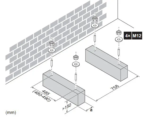
Mounting the outdoor unit
To provide the installation structure
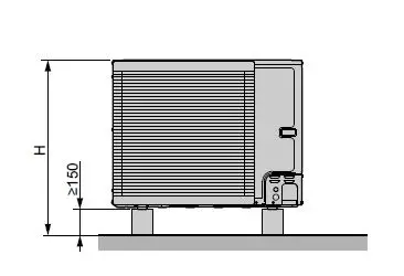
Use 4 sets of M12 anchor bolts, nuts and washers field supply. Provide at least 150 mm of free space below the unit. Additionally make sure the unit is positioned at least 100 mm above the maximum expected level of snow.
 Make sure not to cover the drain holes. Drain holes dimensions in mm.
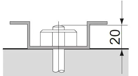
INFORMATION
The recommended height of the upper protruding part of the bolts is 20 mm.
 NOTICE
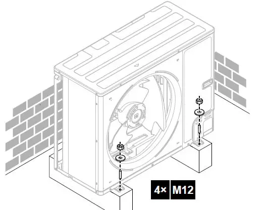
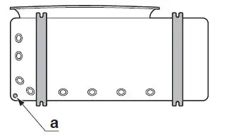
Fix the outdoor unit to the foundation bolts using nuts with resin washers (a). If the coating on the fastening area is stripped off, the metal can rust easily.
To install the outdoor unit
CAUTION
To avoid injury, do NOT touch the air inlet or aluminium fins of the unit.
- Put the sling delivered as accessory through the unit’s left feet.
- Carry the unit using the sling left and the unit’s handles right and put it onto the installation structure.

- Remove the sling, and dispose of it.
- Fix the unit to the installation structure.
 To provide drainage
 To provide drainage
Make sure that condensation water can be evacuated properly.
INFORMATION
If necessary, you can use a drain pan (field supply) to prevent drain water from dripping.
NOTICE
If the unit CANNOT be installed fully level, always make sure that the inclination is towards the backside of the unit. This is required to guarantee proper drainage. If drain holes of the outdoor unit are covered by a mounting base or by floor surface, raise the unit to provide a freeNspace of more than 150 mm under the outdoor unit.

Drain holes (dimensions in mm)
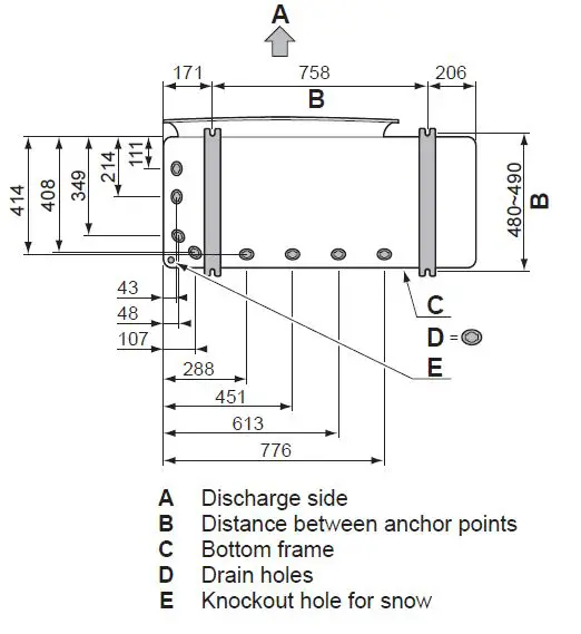
Snow
In regions with snowfall, snow might build up and freeze between the heat exchanger and the casing of the unit. This might decrease the operating efficiency. To prevent this. Remove the knockout hole a by tapping on the attachment points with a flat head screwdriver and a hammer.
 Remove the burrs, and paint the edges and areas around the edges using repair paint to prevent rusting.
NOTICE
When making knockout holes, do NOT damage the casing and underlying piping.
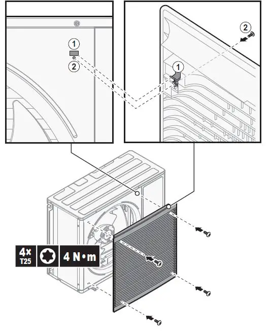
To install the discharge grille
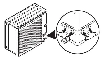
- Insert the hooks. To prevent breaking the hooks.
- First insert the bottom hooks (2×)
- Then insert the top hooks (2×)
- Insert and fix the screws (4×)(delivered as accessory).
Opening and closing the unit
To open the outdoor unit
DANGER
RISK OF ELECTROCUTION, RISK OF BURNING/SCALDING
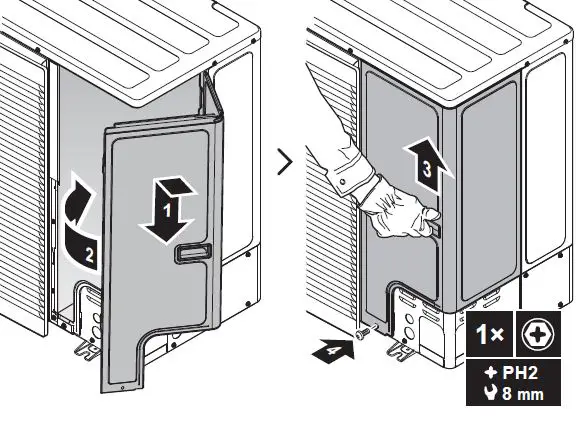
To close the outdoor unit
 Piping installation
Connecting the refrigerant piping
DANGER
RISK OF BURNING/SCALDING
NOTICE
Vibration
To prevent vibration of the refrigerant piping during operation, fixate the piping between the outdoor and indoor unit.
To connect the refrigerant piping to the outdoor unit
- Piping length: Keep field piping as short as possible.
- Piping protection:Protect the field piping against physical damage.
- Do the following
- Remove the service cover (a) with screw (b).
- Remove the piping intake plate (c) with screws (d).
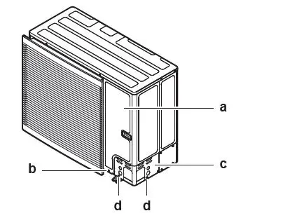
Choose a piping route (a, b, c or d)
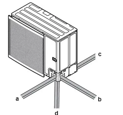
- a Front
- b Side
- c Rear
- d Bottom
INFORMATION
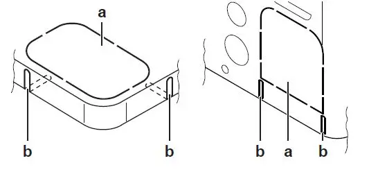 Remove the knockout hole (a) in the bottom plate or cover plate by tapping on the attachment points with a flat head screwdriver and a hammer. Optionally, cut out the slits b with a metal saw.
NOTICE
Precautions when making knockout holes.
- Avoid damaging the casing and underlying piping.
- After making the knockout holes, we recommend to remove the burrs and paint the edges and areas around the edges using repair paint to prevent rusting.
- When passing electrical wiring through the knockout holes, wrap the wiring with protective tape to prevent damage.
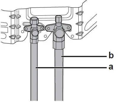
- Do the following:
- Connect the liquid pipe (a) to the liquid stop valve.
- Connect the gas pipe (b) to the gas stop valve.
 Do the following
- Insulate the liquid piping a and the gas piping b.
- Wind heat insulation around the curves, and then cover it with vinyl tape (c).
- Make sure the field piping does not touch any compressor components.
- Seal the insulation ends sealant etc.
- Wrap the field piping with vinyl tape (e) to protect it against sharp edges.
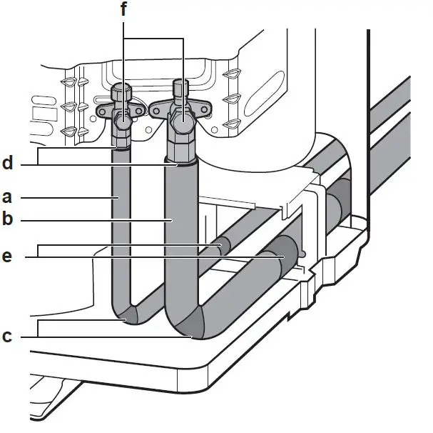 If the outdoor unit is installed above the indoor unit, cover the stop valves f with sealing material to prevent condensed water on the stop valves from moving to the indoor unit.
NOTICE
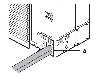
Any exposed piping might cause condensation. Reattach the service cover and the piping intake plate. Seal all gaps (example: a) to prevent snow and small animals
rom entering the system.
 Do not block the air vents. This could affect air circulationinside the unit.
WARNING
Provide adequate measures to prevent that the unit can be used as a shelter by small animals. Small animals tha make contact with electrical parts can cause malfunctions,
smoke or fire.
NOTICE
Make sure to open the stop valves after installing the refrigerant piping and performing vacuum drying. Running the system with the stop valves closed may break the compressor.
Checking the refrigerant piping
To check for leaks
NOTICE
Do NOT exceed the unit’s maximum working pressure PS High on the unit name plate. ALWAYS use a recommended bubble test solution from your wholesaler. NEVER use soap water. Soap water may cause cracking of components, such as flare nuts or stop valve caps. Soap water may contain salt, which absorbs moisture that will freeze when the piping gets cold. Soap water contains ammonia which may lead to corrosion of flared joints between the brass flare nut and the copper flare. Charge the system with nitrogen gas up to a gauge pressure of at least 200 kPa 2 bar. It is recommended to pressurize to 3000 kPa 30 bar in order to detect small leaks.Check for leaks by applying the bubble test solution to all connections. Discharge all nitrogen gas.
To perform vacuum drying
NOTICE
Connect the vacuum pump to both the service port of the gas stop valve and the service port of the liquid stop valve to increase efficiency. Make sure that the gas stop valve and liquid stop valve are firmly closed before performing the leak test or vacuum drying. Vacuum the system until the pressure on the manifold indicates −0.1 MPa −1 bar. Leave as is for 4-5 minutes and check the pressure .
| If the pressure | Then |
| Does not change | There is no moisture in the system. This procedure is finished. |
| Increases | There is moisture in the system. Go to the next step. |
Vacuum the system for at least 2 hours to a manifold pressure of −0.1 MPa −1 bar. After turning the pump OFF, check the pressure for at least 1 hour. If you do NOT reach the target vacuum or CANNOT maintain the vacuum for 1 hour, do the following
- Check for leaks again.
- Perform vacuum drying again.
NOTICE
Make sure to open the stop valves after installing the refrigerant piping and performing vacuum drying. Running the system with the stop valves closed may break the
compressor.
Charging refrigerant
To determine the additional refrigerant amount
| If the total liquid piping length is | Then |
| ≤10 m | Do NOT add additional refrigerant. |
| >10 m | R=total length (m) of liquid piping–10 m×0.050 R=Additional charge kg rounded in units of 0.01 kg |
INFORMATION
Piping length is the one-way length of liquid piping.
To charge additional refrigerant
WARNING
Only use R32 as refrigerant. Other substances may cause explosions and accidents. R32 contains fluorinated greenhouse gases. Its global warming potential (GWP) value is 675. Do NOT vent these gases into the atmosphere. When charging refrigerant, ALWAYS use protective gloves and safety glasses.
Prerequisite
Before charging refrigerant, make sure the refrigerant piping is connected and checked leak test and vacuum drying. Connect the refrigerant cylinder to both the service port of the gas stop valve and the service port of the liquid stop valve. Charge the additional refrigerant amount. Open the stop valves.
To fix the fluorinated greenhouse gases label
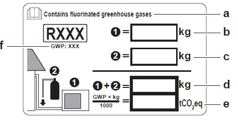
Fill in the label as follows
 a If a multilingual fluorinated greenhouse gases label is delivered with the unit peel off the applicable language and stick it on top of a.
- b Factory refrigerant charge: see unit name plate
- c Additional refrigerant amount charged
- d Total refrigerant charge
- e Quantity of fluorinated greenhouse gases of the total refrigerant charge expressed as tonnes CO2 equivalent.
- f GWP = Global warming potential
 a If a multilingual fluorinated greenhouse gases label is delivered with the unit peel off the applicable language and stick it on top of a.
Electrical installation
DANGER:
RISK OF ELECTROCUTION
WARNING
Rotating fan
Before powering ON the outdoor unit, make sure that the discharge grille covers the fan as protection against a rotating fan. See “4.2.4 To install the discharge grille. ALWAYS use multicore cable for power supply cables.
CAUTION
Do NOT push or place redundant cable length in the unit.
NOTICE
The distance between the high voltage and low voltage cables should be at least 50 mm.
About electrical compliance
Only for ERLA11~16DAV3
Equipment complying with EN/IEC 61000‑3‑12 European/International Technical Standard setting the limits for harmonic currents produced by equipment connected to public low voltage systems with input current >16 A and ≤75 A per phase.
Specifications of standard wiring components
| Component | ERLA11~16DAV 3 | ERLA11~16DAW 1 | |
| Power supply cable | MCA(a) | 30.8 A | 14 A |
| Voltage range | 220~240 V | 380~415 V | |
| Phase | 1~ | 3N~ | |
| Frequency | 50 Hz | ||
| Wire sizes | Must comply with applicable legislation | ||
| Interconnection cables | Minimum cable section of 1.5 mm² and applicable for 230 V | ||
| Recommended field fuse | 32 A, C curve | 16 A or 20 A, C curve | |
| Earth leakage circuit breaker | 30 mA Must comply with applicable legislation | ||
MCA
Minimum circuit ampacity. Stated values are maximum values (see electrical data of combination with indoor units for exact values.
Guidelines when connecting the electrical wiring
Tightening torques
| Item | Tightening torque (N.m) |
| M4 (X1M) | 1.2~1.8 |
| M4 (earth) | 1.2~1.4 |
| M5 (X1M) | 2.0~3.0 |
| M5 (earth) | 2.4~2.9 |
Connections to the outdoor unit
| Item | Description |
| Power supply cable | |
| Interconnection cable |
To connect the electrical wiring to the outdoor unit
NOTICE
Follow the wiring diagram (delivered with the unit, located at the inside of the service cover. Make sure the electrical wiring does NOT obstruct proper reattachment of the service cover.
- Remove the service cover.
- Connect the interconnection cable and power supply 1N~or 3N~ depending on model, see name plate as follows
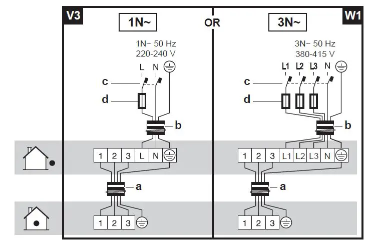
- a Interconnection cable
- b Power supply cable
- c Earth leakage circuit breaker
- d Fuse
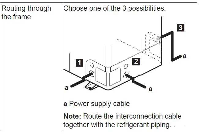
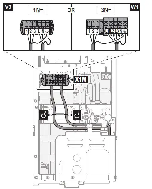 Fix the cables power supply and interconnection cable with a cable tie to the stop valve attachment plate and route the wiring according to the illustration above. Choose a knockout hole and remove the knockout hole by tapping on the attachment points with a flat head screwdriver and a hammer. Route the wiring through the frame and connect the wiring to the frame at the knockout hole.
 NOTICE
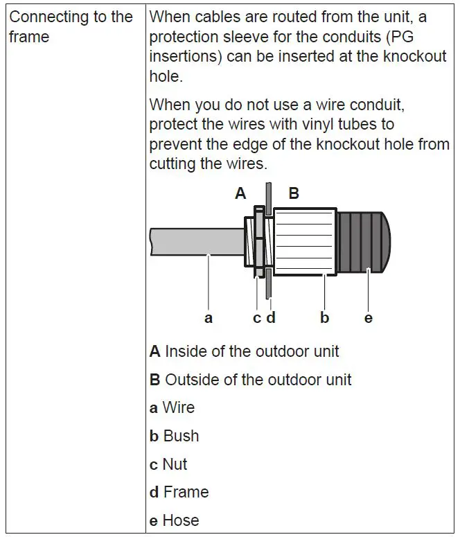
Precautions when making knockout holes. Avoid damaging the casing and underlying piping. After making the knockout holes, we recommend to remove the burrs and paint the edges and areas around the edges using repair paint to prevent rusting. When passing electrical wiring through the knockout holes, wrap the wiring with protective tape to prevent damage. Reattach the service cover. Connect an earth leakage circuit breaker and fuse to the power supply line.
Finishing the outdoor unit installation
To check the insulation resistance of the compressor
NOTICE
If after installation, refrigerant accumulates in the compressor, the insulation resistance over the poles can drop, but if it is at least 1 MΩ, then the unit will not break down. Use a 500 V mega-tester when measuring insulation. Do NOT use a megatester for low voltage circuits.Measure the insulation resistance over the poles.
| If | Then |
| ≥1 MΩ | Insulation resistance is OK. This procedure is finished. |
| <1 MΩ | Insulation resistance is not OK. Go to the next step. |
Turn ON the power and leave it on for 6 hours
Starting up the outdoor unit
Result
The compressor will heat up and evaporate any refrigerant in the compressor measure the insulation resistance again.
To finish the outdoor unit installation
Insulate and fix the refrigerant piping and cables as follows
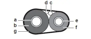
- a Gas pipe
- b Gas pipe insulation
- c Interconnection cable
- d Field wiring (if applicable)
- e Liquid pipe
- f Liquid pipe insulation
- g Finishing tape
Install the service cover.
Starting up the outdoor unit
WARNING
Rotating fan. Before powering ON the outdoor unit, make sure that the discharge grille covers the fan as protection against a rotating fan.
Technical data
A subset of the latest technical data is available on the regional Daikin website publicly accessible. The full set of latest technical data is available on the Daikin Business Portal authentication required.
Piping diagram Outdoor unit
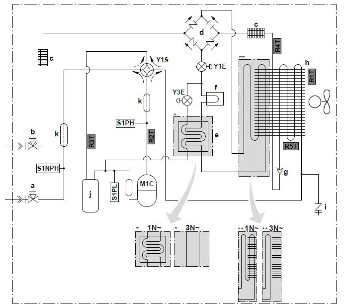
- a Gas stop valve with service port
- b Liquid stop valve with service port
- c Filter
- d Rectifier
- e Economiser
- f Heat sink
- g Distributor
- h Heat exchanger
- i Service port 5/16″ flare
- j Accumulator
- k Muffler
- M1C Compressor
- S1PH High pressure switch
- S1PL Low pressure switch
- S1NPH Pressure sensor
- Y1E Electronic expansion valve main
- Y3E Electronic expansion valve injection
- Y1S Solenoid valve 4 way valve
- Thermistors: R1T Outdoor air
- R2T Compressor discharge
- R3T Compressor suction
- R4T Air heat exchanger
- R5T Air heat exchanger, middle
Refrigerant flow
- Heating
- Cooling
Connections
- Flare connection
- Brazed connection
Technical data
Wiring diagram: Outdoor unit
The wiring diagram is delivered with the unit, located at the inside of the service cover.Translation of text on wiring diagram
| English | Translation | ||
| Connection diagram | Connection diagram | ||
| Compressor SWB | Compressor switch box | ||
| Hydro SWB | Hydro switch box | ||
| Indoor | Indoor | ||
| Outdoor | Outdoor | ||
| Compressor switch box layout | Compressor switch box layout | ||
| Front | Front | ||
| Rear | Rear | ||
| Legend | Legend | ||
| Optional Field supply | |||
| A1P | Printed circuit board main | ||
| A2P | Printed circuit board noise filter | ||
| A3P (only for 1N~ models) | Printed circuit board flash | ||
| Q1DI | # | Earth leakage circuit breaker | |
| X1M | Terminal strip | ||
| (4) Notes | Notes | ||
| X1M | Main terminal | ||
| Earth wiring | |||
| Field supply | |||
| 1 | Several wiring possibilities | ||
| Option | |||
| Wiring depending on model | |||
| Switch box | |||
| PCB | |||


