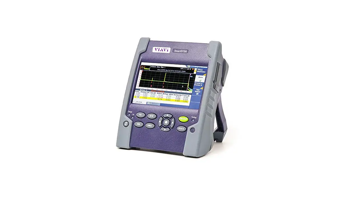
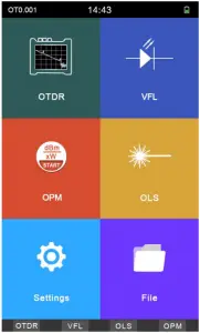
Smart OTDR
Optical Time Domain Reflectometer
User Manual
Foreword
Thank you for purchasing our OTDR (Optical Time Domain Reflectometer). This user’s manual contains useful information about the instrument’s functions and operating procedures of the OTDR. To ensure correct use, please read this manual thoroughly before beginning operation. After reading the manual, keep it in convenient location for quick reference whenever a question arises during operation.
Note
The contents of this manual are subject to change without prior notice as a result of continuing improvements to the instrument’s performance and functions. The figures given in this manual may differ from those that actually appear on your screen.
Every effort has been made in the preparation of this manual to ensure the accuracy of its contents. However, should you have any questions or find any errors, please contact your nearest dealer.
Copying or reproducing all or any part of the contents of this manual without our company’s permission is strictly prohibited.
Safety Tips
Charger:
Input: AC 100V~240V, 50/60Hz; @0.3A~0.5A.
Output: DC 8.4V, 0.5A~1A, Polarity: positive inside, negative outside
Please use the charger in strict accordance with the specifications, or it may cause damage to the equipment
Battery:
Special lithium battery is used in the instrument. In order to fully utilize the performance of the battery, when using the instrument for the first time, please exhaust the battery and then charge the battery. The first charging time should be no less than 8 hours. The charging temperature of the internal battery is from 0°C to 50°C. When the ambient temperature is too high, please terminate the charging for your safety. When the instrument is unused for more than 2 months, it should be charged in time to maintain the battery power; do not remove the battery; please do not let the battery close to the fire source, strong heat; do not open or damage the battery; Temperature for long-term storage of the battery is -20°C ~ 45°C.
Laser Safety
When using this instrument, please pay attention to avoid direct view of the laser output port, and do not look directly at the end of the fiber during testing; After used the instrument, please cover dust cap. When the visible fault locator function is turned on, please do not look directly at the output port of the VFL; and do not look directly at the end of pigtail connected to VFL port to avoid the damage to eyes.
Features:
- Two wavelength: 1310/1550nm
- Measurement distance: 60km
- Touching screen ( Optional)
- Test record can be saved as so format
- Optical power meter/ optical light source/ visual fault locator/ OTDR- -Multi-function tester
- Editable file name and lineNo.
- Support upgrade
- 4 inch ISP Display, 800*480 pixels, Clear and readable in outdoor sunlight
- Quick boot, it takes only 2 seconds to test
2
1. Specifications
| OTDR | |
| Wavelength (nm) | 1310/1550nm |
| Dynamic Range | 22/20dB |
| Measurement Distance | 0-60 km |
| Type of Fiber | 9/125um SM |
| Type of Connectors | FC/PC/; SC/PC (FC/APC SC/APC–Optional) |
| Peak Value of laser | >=30mW |
| Unit | Meter/ inch/ mile |
| Dead Zone of Reflection | 2m |
| Dead Zone of attenuation Event | 12m |
| Accuracy Distance (Reflection Event) | About ±(1m+2 *10(-4)* distance) |
| Storage of records | 200 groups |
| Visual Fault locator (VFL) | |
| Wavelength (nm) | 650nm |
| Output power | >=10mW |
| Mode | CW, 1Hz, 2Hz |
| Fiber type | SM, MM |
| Optical Power Meter | |
| Measurement range dBm | -70~+10 dBm | -50~+26 dBm |
| Wavelength range (nm) | 800~1650 |
| Calibrated wavelength | 850, 1300, 1310, 1490, 1550, 1625 |
| Detector | InGaAs |
| Accuracy | <±3% (-10dBm, 22°C) |
| Resolution | Linearity: 0.1%, Non-linearity: 0.01dBm |
| Connector | Changeable FC/PC SC/PC ( ST as Optional) |
| Optical Light Source | |
| Emitter | FP-LD |
| wavelength (nm) | 1310/1550nm |
| Connector | FC/PC (SC/ST as optional) |
| Output power | ≥-5dBm |
| Output stability (dBm) | ±0.04@20°C @15min |
| Modulation | CW/270Hz/1KHz/2KHz |
| Fiber type | SM |
| Others | |
| LCD | 3.97inch, 800*480pixels, IPS screen |
| Battery | 7.4V/4400mAH Lithium-ion battery, >5000 tests |
| Temperature | Work temperature: -5 ~ 50 °C, storage temperature: -10 ~ 60 °C |
| Humidity | 0~85%(Non-condensing) |
| Dimensions (mm) | 190×84×52 |
| Weight (g) | 375 |
4
2. Functions
2.1 Front Panel
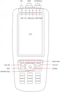
5
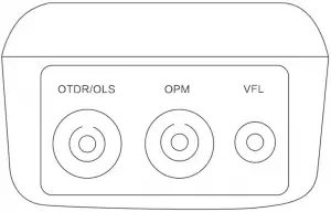
2.2 Top Interface
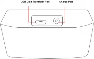
2.3 Bottom Interface
6
3. LCD Display
4.Operations
4.1 ON/OFF & Charge
Turn On: Press ![]() to turn on the tester, the PWR LED lights up and the display shows the main menu
to turn on the tester, the PWR LED lights up and the display shows the main menu
7
Turn Off: Press “OFF”, the display shows: Confirm to turn it off? Yes: OK; NO: ESC
Turn off by force: when the tester works abnormally, press ![]() for 6 seconds to turn off the tester by force.
for 6 seconds to turn off the tester by force.
During normal use, the battery level will be displayed in the upper right corner of the tester. When the battery level is too low, the battery level symbol will turn red as warning. Please charge it with the charger provided by factory. The remaining charge will be displayed at the top of the screen. The red color of LED on the charger indicates that charging is in progress, and the green color means it is already fully charged.
After turn on the device, please enter into the system settings from the main menu, set the parameters like date, time, backlight, brightness, auto power off time, button tone and other information.
4.2 Connect the fiber
Note: In any case,do not exposure eyes to the emitted light directly;
The light is harmful to your eyes;
Before connecting the fiber,please check whether the connector type matches or not, and also check whether the connector is clean or not; both the unmatched connectors and the contaminated connectors can cause inaccurate measurements and can even damage the the instrument.
Clean the end face of connector and pigtail:
Before connecting the pigtail, please clean the end face of the pigtail by waterfree alcohol; After the alcohol has evaporated, connect it to the device. Please cover the dust cap when not in use
4.3 Setting measurement conditions
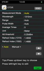
4.3.1 Auto Test
- Press OTDR/parameters
- Choose wavelength
- Choose Test Mode
- Choose Automatic
8
4.3.2 Manual Test
The manual test is a professional test mode, and operators can set the test conditions according to the actual condition of the fiber
- Press OTDR/parameters
- Choose Test Mode: Manual
- Choose Average time: we suggest 10 as Minimum:
- Choose suitable parameters
9
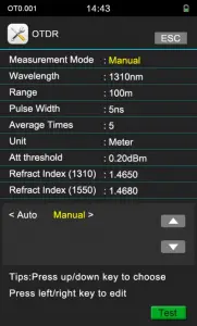
Experienced engineers can select the most suitable measurement parameters; according to the accumulated experience of the measurement and the situation of the field curve, which can improve the measurement efficiency and quickly find the fault point.
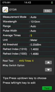
4.3.3 Real-time Test
- Press OTDR/parameters
- Choose wavelength
- Choose Test Mode
- Choose Test range
- Choose pulse width
- Choose Average times: Real
10
4.4 Test
- PRESS F4 to Test
- Press F4 in the” OTDR” menu
4.5 Curve analysis
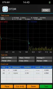
After testing, the curve, test results and event list will show in the display
11
4.6 Measure Distance and Average Loss
Press F2, choose cursor A , cursor B, or cursor A+B, move the cursors to left or right through press the direction keys, the distance and average loss between B-A will display in the gray area above the curve
4.7 Save& Browse&export record
4.7.1 Save record
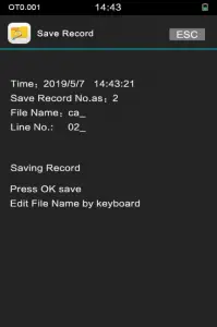
After testing, press F3 to save the record, there will be prompt message shows in the display, operators can edit the file name and prefix via keyboard, Enter the starting number of the file name, press ” OK” to save the record; and the number of the line will Automatically add 1 next time
This tester can save 200 groups of records
12
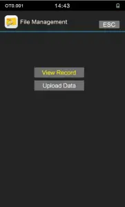
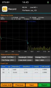
4.7.2 View Record
From the main menu of the home page/File/REC View;To view the records by moving or pressing F2 to view the previous record and press F3 to view the next record
13
4.7.3 Data Upload
Connect the instrument to the PC with the USB data cable. The USB interface is at the bottom of the instrument, Turn on the instrument, enter the main menu/Files/Data Upload, and save the records to the software. The software can do Analysis, archiving and printing operations to test records
14
5. Optical Power Meter
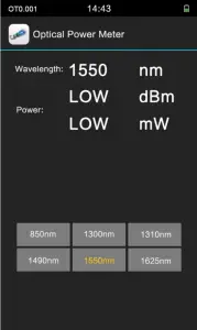
Calibration Instructions:
when the power meter shows deviation values, please clean the detector firstly. If there is still a small deviation after cleaning, you can perform manual calibration. The operation is as follows: Press the up/down direction key to display Adjust State (above 1300nm) and press “#” key enters manual calibration mode, press the up and down keys to fine tune, press 2 and 8 keys to coarse adjustment, press OK to save.
6. Visual Fault Locator (VFL)
15
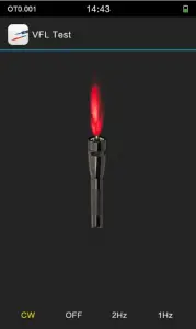
CW: continuous light; OFF: turn off the light; 2Hz: Fast Blink; 1Hz: Slow Blink
Reminder: When using the VFL function, Do not see directly to the optical interface of the instrument and the end of the pigtail connected to the optical interface , otherwise it may hurt the eyes or even blindness!
16
7. Optical Light Source
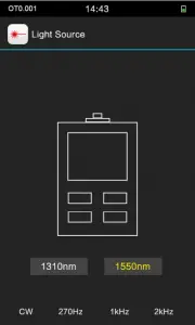
Two wavelengths:1310nm,1550nm
CW:Continuous light output, 0Hz.
270Hz, 1kHz, 2kHz : Non-continuous light output, Simulate actual data signal transmission
8.Upgrade software
8.1 Install Driver
Copy the CH340 driver (USB serial driver)_XP_WIN7 shared file in the CD or U disk to the computer, unzip it, and then click SETUP.EXE to install it. When the installation is successful. After connecting the PC and the instrument, you can see the USB-SERIAL CH340 under Device Manager/Port. At this point, you can upgrade the software software FlyMcu and the instrument data transmission.
17
8.2 FlyMcu Firmware download tool
Copy the FlyMcu application from the CD or USB flash drive to your computer and double-click it to open it.
I. Choose serial port : button 1(see the red circle as below) Port, choose the COM of USB-SERIAL CH340
II. see the button 2 (see the pic as below) at the bottom left , choose “DTR low reset, ,RTS high level into BootLoader” (the fourth option)
18
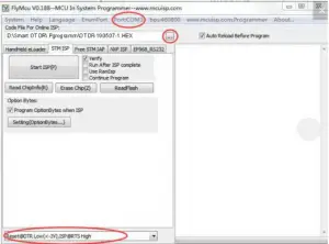
8.3 Upgrade firmware
Click the FlyMcu button 3. Select the HEX upgrade file of the main program and click Start Programming. The upgrading progress will be shows on the right window w. Do not perform other operations. Wait until the upgrade completed
8.4 Driver and algorithm program upgrade
This upgrade is slightly different from upgrade of the main application firmware. Please follow the process below to complete the driver and algorithm upgrade.
a: Unplug the USB cable and turn off the FlyMcu software and open the OTDR tester.
b: Enter the system settings / version information, do not do any operations on the device now
c: Plug in the USB data cable and open the FlyMcu software. Then select the correct serial and level mode as described above. Click the FlyMcu button 3, select the HEX upgrade file of the drive algorithm, click Start Programming, the right window will prompt the upgrade progress, do not perform other operations, and wait for the upgrade to complete.
9. Simulation analysis software
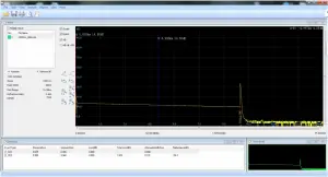
The device is equipped with simulation analysis software, which can preview the curve from computer, analyze the curve offline and preview and print the curve. It is convenient for operators to manage and maintain the data of fibre link.
19
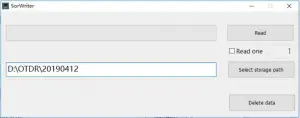
9.1 Batch read and storage of test data
Connect the device to the PC through the USB data cable, boot the machine, follow the instructions in Chapter 8 to install the CH340 driver on the PC, use the WriteSor application, obtain the test record saved by the instrument to the PC, select the storage path and save the location. The data can read and converted to the sor format
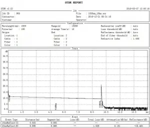
9.2 Print Test Report
Use the OTDRViewer simulation analysis software to view the OTDR test report through print preview. The test report contains the information such as test conditions, test curves, link loss, average loss, event list, etc., and the test reports can be batch printed after confirmation.
20
The software can open, print preview, and print curves through files.Through the report wizard, you can set to print multiple test curves per page. The test report is shown as below:
10. Maintenance and troubleshooting
10.1 Clean connectors
The connectors (end face of the pigtail) must be kept clean during use. When the device fails to test the normal curve, or the test result is inaccurate, please consider cleaning the connector firstly.
When cleaning, be sure to turn off the OTDR and VFL functions. Unscrew the connector and wipe the connecting end face with a special dust-free paper towel or cotton swab moistened with alcohol. At the same time, after using the instrument, please cover the dust cap to keep the connector clean.
10.2 Clean Display
The display of this OTDR adopts 3.97-inch IPS color LCD with touch screen (Optional). When using it, you can’t use a sharp object to click on the LCD screen. When cleaning, operators can wipe the LCD screen with a soft paper. Do not wipe the LCD with an organic solvent, as this may cause damage to the LCD.
10.3 Calibration
It is recommended to calibrate the device every two years. Please contact the supplier for specific calibration items.
10.4 Trouble shootings
| Fault | Reasons | Solutions |
| Can’t turn on | Low power | Charge the battery and observe the charger indicator. If CHR LED is red continue charging. Otherwise, contact the supplier. |
| Can’t be charged properly | The use environment does not meet the charging conditions | Charge the device in an environment of 0 °C ~ 50 °C |
| Battery problem, or internal circuit problem | Contact the supplier to replace the battery | |
| Unable to measure normal curve | Parameter settings are incorrect | Reset the correct test parameters |
| The end of the fiber is contaminated | Clean the end face of fiber | |
| Connector of device is damaged | Change the connector | |
| Connectors do not match | Change the matched connector | |
| The test curve has a large burr. Waveform is not smooth | Output connector is not connected correctly | Reconnect the appropriate output connector |
| Pulse width is too low | Increase value of pulse width | |
| Saturated (flat top) phenomenon at the front end of the test curve | Pulse width setting is too large | Reduce value of pulse width |
| At the beginning of the test curve, the reflection peak drops slowly and tailing occurs. | The end of the fiber is | Clean the end face of fiber |
| Connector of device is damaged | Change the connector | |
| Connectors do not match | Change the matched connector | |
| Unable to test reflection peak of fiber end | Range of setting too low | Increase value of range |
| Pulse width is too low | Increase value of pulse width |
22
| False report of test curves | Quality of test curve is bad; Event threshold setting is too small | Increase value of test pulse width and increase the value of event threshold |
| The measured fiber length is not accurate | Parameter settings are incorrect | Reset the appropriate parameters |
| Refractive index setting is not | Reset fiber refractive index | |
| The measured average fiber loss value is not accurate | The front end of the test curve is | Clean end face of fiber interface |
| The cursor position is not set | Reset cursor position |
- The above description is for reference only. Please refer to the new instructions for detailed usage. If you have any questions during the use of the device,please contact the supplier to resolve it.
- During the use of the device, It is forbidden to disassemble the device without authorization, otherwise the warranty will be lost!
11. Packing List
| NO | Name | Qty |
Standard accessories | ||
| 1 | OTDR with FC/UPC connector | 1 |
| 2 | AC/DC Charger | 1 |
| 3 | CD (software and user manual) | 1 |
| 4 | User manual | 1 |
| 5 | Test Report | 1 |
| 6 | Softcase | 1 |
Optional Accessories | ||
| 1 | SC /ST connector for OTDR Port | 1 |
| 2 | SC/ST Connector for OPM port | 1 |
Note: The default connector of this OTDR FC/UPC, and the FC/APC type is optional. The above contents are subject to change without notice due to the need for design improvement.
23


