![]() HBOC-C Oil Level Controller
HBOC-C Oil Level Controller
Instruction Manual
Quick guide for OIL MANAGEMENT SWITCHES
Covers HBOC and HBOR both mk1 and mk2 versions.
Setup information is available in the manual which is available under download on www.hbproduct.dk
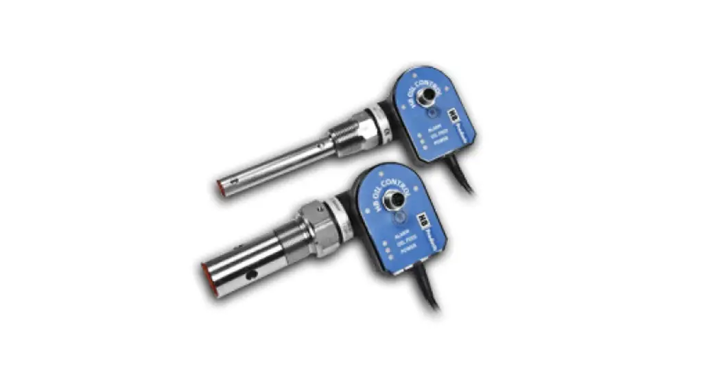
Introduction
The sensors are designed for control of oil levels igas HBOC and in Liquid ammonia HBOR HBOR will also be useable for measuring water inoil.
Both sensors can control a level based on a singleswitch. These sensors replace the common mechanical float and the two-switch solution where a minimum and maximum level switch is used for controlling the level.
The difference between mk1 and mk2 is the output on the cable.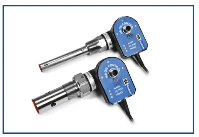
- HBOC/C and HBOR/C has 24 VDC max 24 W output on the cable
- HBOC/C mk2 and HBOR/C mk2 has 24 V AC/DC max 24 W output on the cable
Mk2 version are labeled mk2. Mk1 versions are not labeled mk1
Installation
The sensor is mounted either on a compressor or an oil separator. On a compressor, an adapter flange can be provided as an accessory. The sensor is sealed with Teflon tape or liquid gasket before installation. Dependent upon the thread type, the gasket consists of:
- NPT thread = Teflon tape or liquid gasket
- BSPP & UNEF = Aluminum washer/gasket
Electrical connections
HBOC/C and HBOR/C can supply a magnetic valve, or it can be connected to the central control via the sensor’s control/alarm output. See the diagrams below for the two
HBOC/C and HBOR/C – mk1
(DC version – DC supply and DC output on cable)
DC version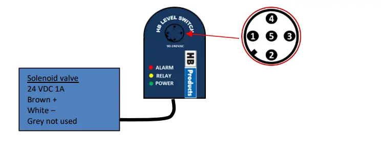
- Brown +24 VDC
- White – common
- Blue Alarm Output pot. free 1A
- Black Alarm Output pot. free 1A
- Grey DI Run-in signal 5-24 V DC
HBOC/C and HBOR/C – mk2 (AC version – AC/DC supply and AC/DC output on cable)
AC version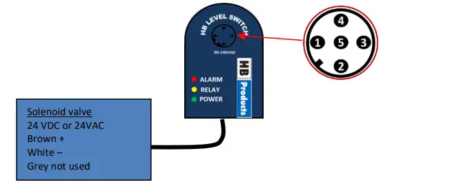
- Brown +24 VDC or 24 V AC
- White – common or 24 V AC
- Blue not used
- Black Digital out 24VDC 30 mA
- Grey DI Run-in signal 5-24 V
The sensor controls the valve independent of other parts of the system. The function starts to work when the supply is connected. The control function can be activated/deactivated via an external run signal with “Run in” (pin 5) or work continuously
LED indication:
- 3 x green LEDs indicate oil level
- Green Power LED constant light indicate sensor is standby – not controlling Green Power LED flashes when the sensor is in control operation.
- Yellow LED indicates supply is open to magnetic valve
- Red LED indicates ALARM
| LED signal | ON/OFF/Frequency | Functionality |
| Green (3x) | ON | Oil detected |
| Flash | Turbulence in the compressor housing | |
| OFF | Oil is not detected | |
| Green POWER | ON | Standby power connected |
| Flash | In operation or when the sensor is connected to HB Tool. (Red and yellow LED also flashes) | |
| OFF | No supply | |
| Yellow | ON | Activation/supply to the magnetic valve |
| OFF | Magnetic valve is not being supplied | |
| Red | ON | Alarm. Activated automatically according to a calculated time span if oil has not been detected (oil cycle x alarm counter = Time before alarm goes off). Output relay (pin 3 & 4) is activated. |
| OFF | Oil level reached in accordance with the calculated time span / number of oil cycles. | |
| Flash | Sensor is faulty |
Calibration:
HBOR is pre-calibrated upon delivery and ready for use in ammonia systems only. If the sensor is used in other systems/applications, please contact HB products
HBOC is pre-calibrated upon delivery and ready for use in refrigeration systems using conventional mineral and PAO oils. If the HBOC is used in other oil types a calibration might be needed. This calibration is done by using the HB tool connected via an USB cable.
Calibration instructions:
Both a calibration in gas an oil must be done:
A zero calibration is performed when the switch is in gas. The calibration is done by clicking on the zerocalibration button in the tool. A span/max calibration is done when
the switch is covered with oil. Thecalibration is done by clicking on the span-calibration button in the tool.
Fault Detection
| Fault | Reason | Correction of fault |
| No LED is on. | No supply to the sensor or defective cable/plug | Check and find faults in the power supply. Change the supply cable. |
| Sensor does not trigger even though there is oil. | Quality/type of oil is different from that used during factory calibration. | Recalibrate the sensor. |
| Red alarm | Oil level has not been attained during the specified number of oil cycles. | Check system oil return. Check oil filter and magnetic valve if necessary. |
| 3 x green flash | There is oil turbulence in the compressor housing. | Change “filter func/time cons” to a higher value. |
| No output (3 x green LED are on, but the output signal is not active) | Check the setup of the parameters/which contact function has been selected, NC or NO (Normally closed/Normally open) | Change the setup using the tool. |
| Delay in sensor activation | May be caused by gas and foam bubbles in the system. | Check if the sensor is placed optimally. |
| No detection | Fault in the electronics | Send the sensor to be repaired. |
| Red LED flash | Sensor is faulty | Contact supplier |
More information
For further information please download the full instruction manual from our homepage: www.hbproducts.dk. You find it under downloads and then instruction manuals
![]() HBOC/C and HBOR/C quick guide 001 EN
HBOC/C and HBOR/C quick guide 001 EN
December 2021


