![]()
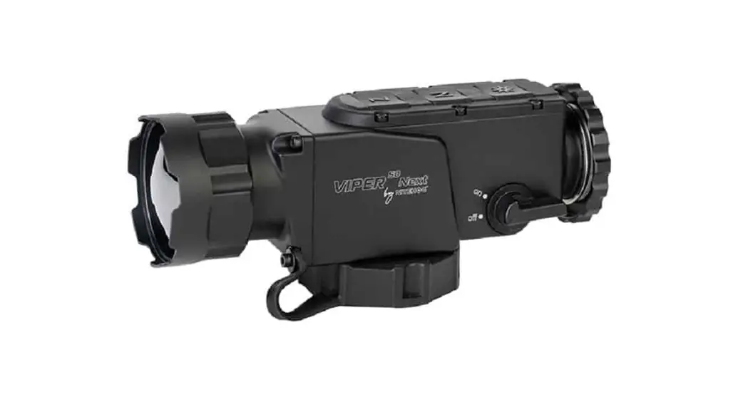
Viper 50 Next Dual Thermal Imaging Device
INSTRUCTION MANUAL
Viper 50 Next Dual Thermal Imaging Device
IMPORTANТ!
Make sure to carefully read the present manual before using the device to ensure its safe exploitation.
Thoroughly test the device before use after it has been left in storage for a long period of time.
Disassembling the device is prohibited, except in authorized repair centers.
The external optical surfaces should be clean at all times. Touching the optical surfaces with bare hands is not recommended.
Sand and sea water can damage the optical coatings!
Do not point the device directly at the sun!
Image performance (quality) depends on the scenery and the atmosphere conditions. The contrast of the image may vary as a function ofthe timeof day due to the effect
of the sun. For example, at sunset objects will have absorbed different levels of heat resulting in greater temperature differences and better contrast.
When storing the device for a longer period of time, the battery has to be removed and stored in polyethylene bags to prevent contact with metal. It is recommended to recharge the battery every two to three months.
Condensation can cause fogging of the external optical surfaces! Condensation occurs when:
- Moving the device from cold to warm place or vice versa;
- The device’s temperature differs significantly from the ambient one;
- Using the device in places with high humidity.
When the temperature of the device is equalized with the ambient one, the condensation disappears. Use the cleaning cloth to remove moisture. Condensation also can be prevented with anti-fogging sprays or with the provided rubber pieces. Condensation on the objective does not affect the performance of the device!
Clean the lens surfaces with the Lens Pen®.
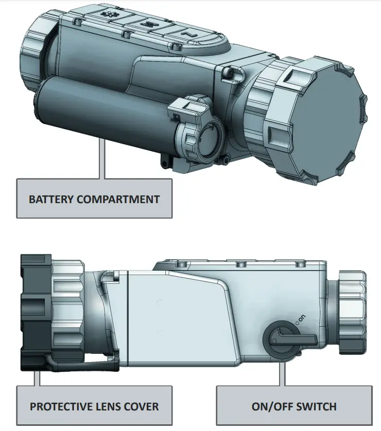
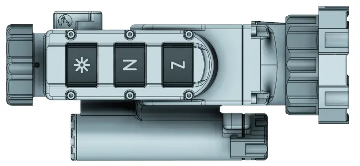
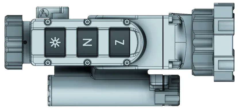
DEVICE OVERVIEW
![]() NOTE
NOTE
All images used in this instruction manual are for illustrative purpose only. Actual product may vary due to product enhancement.
DELIVERY SET
| N | DESCRIPTION | QTY. | |
| 1 | Thermal Imaging multifunctional device Viper 50 Next | ✓ | 1 |
| 2 | Transport Box | ✓ | 1 |
| 3 | Accessories box | ✓ | 1 |
| 4 | Cordura pouch/soft bag ✓ | ✓ | 1 |
| 5 | Rechargeable batteries 18650 | ✓ | 2 |
| 6 | Battery charger | ✓ | 1 |
| 7 | Cleaning cloth | ✓ | 1 |
| 8 | Lens Pen® | ✓ | 1 |
| 9 | Neck strap | ✓ | 1 |
| 10 | Protective rubber lens cap | ✓ | 1 |
| 11 | Rubber protector for the collimator thread | ✓ | 1 |
| 12 | Counter-ring | ✓ | 1 |
| 13 | Sticker with Nitehog logo | ✓ | 1 |
| 14 | User guide | ✓ | 1 |
| 15 | Quick start guide | ✓ | 1 |
| 16 | Certificate of quality | ✓ | 1 |
PRODUCT OVERVIEW
Viper 50 Next multi functional thermal imaging device is purposefully designed for installation in front of daytime rifle scopes or other observation devices as well as a standalone hand held device, ensuring clear view in variety of environmental conditions, including fog, rain, snow, smoke, total darkness. The sophisticated ultra lightweight and low-profile design of the Viper 50 Next multi functional thermal imaging device eliminates the need to remove the day sighting equipment since the Viper 50 Next mounts easily directly in line with a standard daytime rifle scopes without the need of tools. Such a combination allows the user to avoid re-zeroing the rifle every time the sight setup is changed since the primary sight remains undisturbed. The point of impact remains the same no matter how often or how many times the clip-on is mounted. Viper 50 Next is based on the A-CORE module with proven 320×240 pixels detector resolution and ultra small 12 μm pitch size. The housing is made of durable and extremely resistant magnesium alloy and is coated with matte anti-reflective coating.
![]() NOTE
NOTE
Read the instructions carefully to familiarize yourself with the capabilities of the device!
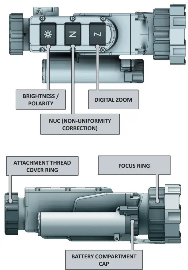
CONTROLS
![]() ATTENTION!
ATTENTION!
The main operations are performed through the buttons ![]() and
and ![]() .
.
![]() NOTE
NOTE
The integrated functions of the device exceed the number of controls. Some features are triggered by a combination of buttons or temporary pressing and holding the buttons.![]() ATTENTION!
ATTENTION!
Turn off the device after usage, otherwise you can permanently damage the battery!
| BUTTONS | SHORT PRESS | LONG PRESS |
| Digital zoom/in observation tion mode | When the device is switched on, the SRF function is activated. | |
| Infobox/in Clip-on mode | ||
| NUC activating | Activating the Auto Isotherm Palette. When the device is switched on, the Auto Isotherm pictogram is activated | |
| Changes between four values of the display luminance | When you are not in the Menu function: Inverts the image between white and black mode | |
| In the menu function: quick Menu exit | ||
| Switch between Clip-on and observation mode | ||
| Activating the Menu of the device. |
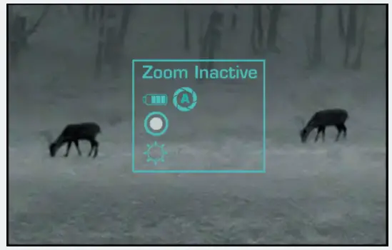
![]() DIGITAL ZOOm
DIGITAL ZOOm
A long press of the ![]() button activates the SRF function. Short press of the
button activates the SRF function. Short press of the ![]() button in monocular mode activates the digital zoom x2, x4.
button in monocular mode activates the digital zoom x2, x4.
The current digital zoom is shown at the top-right corner of the screen.
![]() NOTE
NOTE
The digital zoom reduces the quality of the image!
For a larger and scalable image and to facilitate the operating with the menu during the initial individual adjustment, please switch to observation mode.
• Quick function for switching between observation and clip-on mode: hold down the ![]() button and the
button and the![]() button simultaneously. The pictogram for indication of the respective mode appears in the center of the image for 2 seconds.
button simultaneously. The pictogram for indication of the respective mode appears in the center of the image for 2 seconds.
NUC (NON-UNIFORmITY CORRECTION)
The picture quality highly depends on the sensor temperature. Minimal change in temperature is reflected in visible imperfections of the picture- vertical lines, the appearance of light and dark pixels, etc.
We recommend the use of Auto mode, in which the calibration frequency depends on the temperature characteristics of the sensor. The NUC algorithm can be activated manually by pressing the ![]() button. When Auto NUC function is activated, the following symbol
button. When Auto NUC function is activated, the following symbol ![]() will be displayed on the screen for 5 sec., after that, the pictogram will dis- appear. The symbol
will be displayed on the screen for 5 sec., after that, the pictogram will dis- appear. The symbol ![]() will appear in the top left corner on the screen and will be high- lighted in red as a warning for 2 seconds before the NUC is performed automatically.
will appear in the top left corner on the screen and will be high- lighted in red as a warning for 2 seconds before the NUC is performed automatically.
When the Auto NUC function is deactivated the NUC procedure will be carried out manually only when pressing the ![]() button.
button.
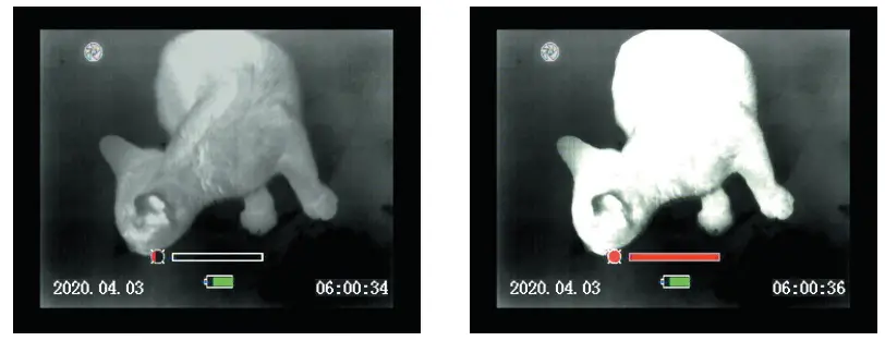
![]() BRIGHTNESS / POLARITY
BRIGHTNESS / POLARITY
The device has four fixed values of the display luminance, marked with the following icons:![]()
When using the device in low lighting conditions and for an extended period of time, consider lowering the brightness levels to extend the battery life and to avoid eye fatigue.
A single short press of the button ![]() shows the current Luminance value. Pressing the button again in close succession will cycle through the available luminance values. The value of the manual luminance option can be configured through the user menu. Press and hold the
shows the current Luminance value. Pressing the button again in close succession will cycle through the available luminance values. The value of the manual luminance option can be configured through the user menu. Press and hold the ![]() button for more than 2 seconds to invert the image, i.e. warm object appear in black hot or in white hot and vice-versa. The change of polarity is denoted by the BH or WH symbols that appear on the screen for 2 seconds.
button for more than 2 seconds to invert the image, i.e. warm object appear in black hot or in white hot and vice-versa. The change of polarity is denoted by the BH or WH symbols that appear on the screen for 2 seconds.
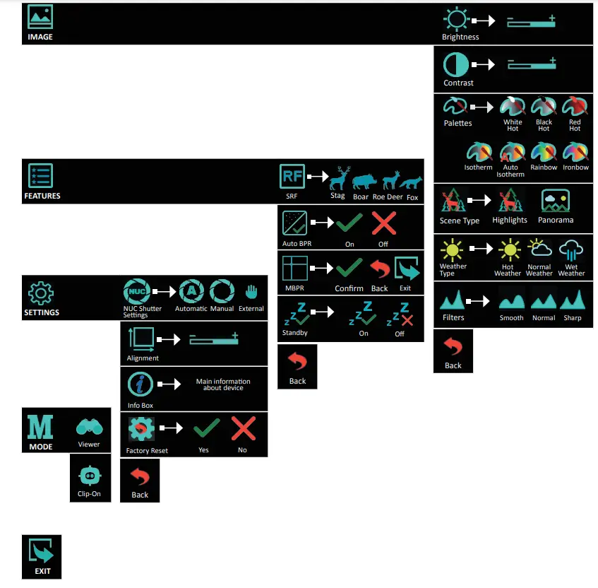
5.1 Navigation
ATTENTION!
The buttons![]() and
and ![]() are dual purpose buttons!
are dual purpose buttons!
Besides the main and secondary functions, they also serve for entering and navigation through the menu.
| BUTTONS | SHORT PRESS |
| Activates the menu | |
| Moves the cursor up | |
| Moves the cursor down | |
| Function select |
5.2 Appearance
![]() ATTENTION!
ATTENTION!
When the Menu is activated and the user is inactive for more than 20 seconds, the Menu is automatically deactivated.
The function is not active in the Alignment and Manual Bad Pixel Replacement (MBPR) sub-menus.
![]() NOTE
NOTE
To quickly exit the device Menu function, hold down the ![]() (Brightness) button for more than 3 seconds.
(Brightness) button for more than 3 seconds.
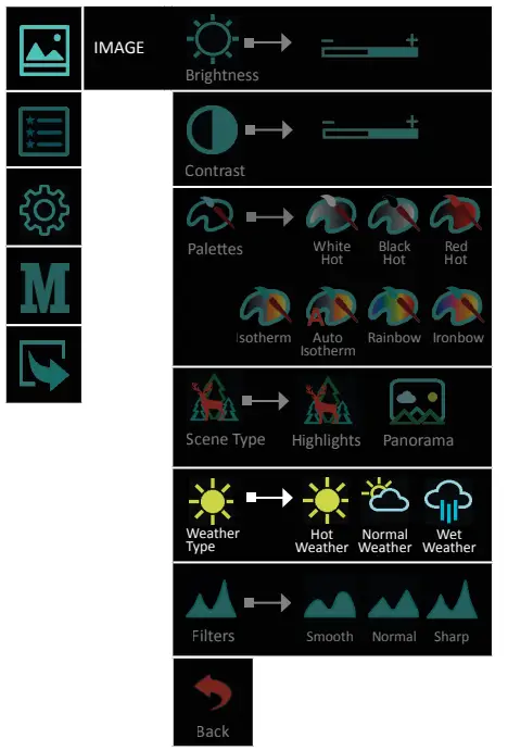
5.2.1 .1 Brightness![]()
5.2.1 Image![]()
Selecting Brightness gives the opportunity to set your own user-defined level of image brightness.
Brightness is not related with the Luminance adjustment performed by the button ![]() !
!
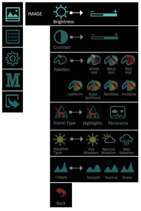
5.2.1 .2 Contrast ![]()
Selecting Contrast gives the opportunity to set your own user-defined level of image contrast (Gain).
Increasing the contrast value will ensure better object contrasting and easier detection. However this will decrease the details on the observed object. Decreasing the contrast value will make the details visible.
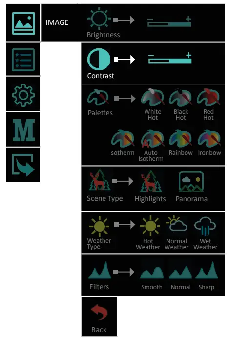
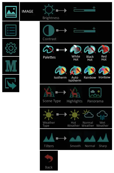
5.2.1 .3 Palettes![]()
A variety of color palettes can be used:
White Hot, Black Hot, Red Hot, Iso therm, Auto Isotherm, Rainbow and Ironbow.
| White Hot | |
| Black Hot | |
| Red Hot | |
| Iso therm | |
| Auto Iso therm | |
| Rainbow | |
| Ironbow |
The pictogram in the main menu shows the active user selection.
![]() White Hot and
White Hot and ![]() Black Hot – Choosing Black Hot (warmer objects appear in black) and White Hot (warmer objects appear in white) is up to user’s personal preference.
Black Hot – Choosing Black Hot (warmer objects appear in black) and White Hot (warmer objects appear in white) is up to user’s personal preference.![]() Red Hot – recommended mode for prolonged observation. The image is red black to minimize the blue light emitting from the display and is more comfortable on the eyes.
Red Hot – recommended mode for prolonged observation. The image is red black to minimize the blue light emitting from the display and is more comfortable on the eyes.![]() Isotherm – the objects above the threshold temperature are colored in different shades of red.
Isotherm – the objects above the threshold temperature are colored in different shades of red.
The temperature threshold can be set (increase/decrease) by the temperature scale shown.
![]()
Increasing the threshold value ignores the colorization of the colder objects.
This option is highly dependent from the distance to the object. It is highly recommended to try different values of the threshold in the daily usage to find the right value for
your personal preference.
![]() Auto Isotherm – the AUTO Isotherm mode enables a marked object to be set as the lowest temperature object in the scene, and the other objects in the scene with higher temperatures are highlighted with yellow-red colors with graduation to this temperature threshold automatically.
Auto Isotherm – the AUTO Isotherm mode enables a marked object to be set as the lowest temperature object in the scene, and the other objects in the scene with higher temperatures are highlighted with yellow-red colors with graduation to this temperature threshold automatically.
When activating the function (with long press of the ![]() button) a marker appears on the center of the screen and pictogram notifying the current mode. The pixels around the marker are taken as a minimum threshold temperature value. Setting the value (marking the object) is performed by short pressing the Brightness button. To deactivate the mode long press the brightness button
button) a marker appears on the center of the screen and pictogram notifying the current mode. The pixels around the marker are taken as a minimum threshold temperature value. Setting the value (marking the object) is performed by short pressing the Brightness button. To deactivate the mode long press the brightness button ![]() to enter WH/BH mode and the pictogram disappears. The activation and deactivation of this feature should be available also
to enter WH/BH mode and the pictogram disappears. The activation and deactivation of this feature should be available also
from the menu.
![]() Rainbow and
Rainbow and ![]() Ironbow – The palettes Rainbow and Ironow help increase chances for recognition & identification of the objects.
Ironbow – The palettes Rainbow and Ironow help increase chances for recognition & identification of the objects.
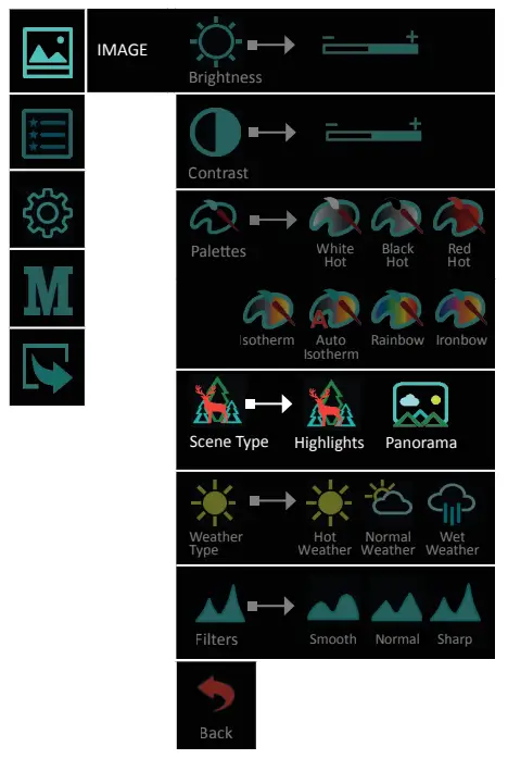
5.2.1 .4 Scene Type ![]()
Two types of auto contrasting, for better performance:
![]() Highlights – this type of image contrasting is suitable for detection and observation.
Highlights – this type of image contrasting is suitable for detection and observation.![]() Panorama – The picture is very stable during changes in the dynamics of the scene. Suitable for observing panoramic scenes with combination of: forest and sky, earth and sky, scenes on the horizon, etc.
Panorama – The picture is very stable during changes in the dynamics of the scene. Suitable for observing panoramic scenes with combination of: forest and sky, earth and sky, scenes on the horizon, etc.
The pictogram Scene Type in the main menu shows the active user selection.
5.2.1 .5 Weather Type![]()
The image quality is strongly depending on weather conditions. When the weather is wet (fog, rain,etc.) the dynamic range of the scene is reduced, causing the contrast of the
image to lower. To prevent this effect, this option provides a filter, that enhances the details of the low contrast image in wet weather conditions (incl. fog and haze). You may choose between 3 filters:
| Hot Weather | |
| Normal Weather | |
| Wet Weather |
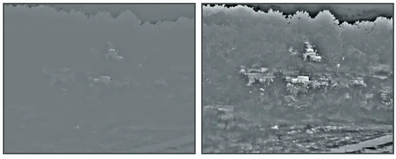
Wet and foggy weather conditions with Normal Weather Type Filter
Wet and foggy weather conditions with Wet Weather Type Filter
![]() NOTE
NOTE
During good weather conditions please select ![]() (normal weather). Otherwise the image will be noisy.
(normal weather). Otherwise the image will be noisy.
5.2.1 .6 Filter![]()
For a more detailed image and clear edges, you can switch between 3 levels of image sharpness:
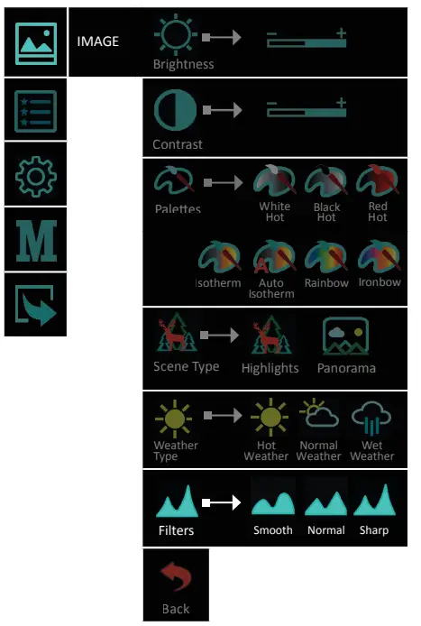
| Smooth | |
| Normal | |
| Sharp |
The pictogram in the main menu shows the active user selection.
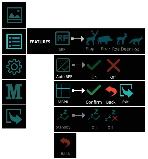
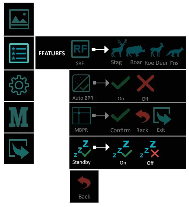
5.2.2 .1 SRF![]()
5.2.2 Features![]()
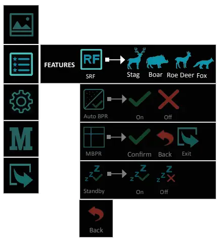
Viper 50 Next is equipped with a stadiametric range finder which allows the user to determine the approximate distance to an object of known size with reasonable accuracy.
Activate the Stadiametric Range Finder (SRF) function with long presses of the ![]() button or by selecting it from the Features мenu.
button or by selecting it from the Features мenu.
You will see on the display: measurement bars, icons of four reference objects and respective distances for these objects.
Position the lower fixed bar under the object being ranged.
By pressing the ![]() button for UP or
button for UP or ![]() button for DOWN, move the upper horizontal bar relative to the lower fixed bar until the object fits entirely between the two bars.
button for DOWN, move the upper horizontal bar relative to the lower fixed bar until the object fits entirely between the two bars.
The distance to the object is automatically recalculated as you move the upper line.
Exit the range finder mode with a short press of the brightness button.
There are four predefined silhouettes for the reference objects:
| Stag (1.40m) | |
| Boar (0.85 m) | |
| Roe deer (0.70m) | |
| Fox (0.40m) |
5.2.2.2 Auto BPR![]()
The AUTO BPR functionality gives the opportunity to automatically correct and clear bad pixels that have appeared on the microbolometer.
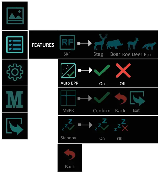
The On/Off function is visualized with an ![]() or a check mark
or a check mark ![]() above the main icon.
above the main icon.
Activating/deactivating of the function is done by briefly pressing the ![]() button.
button.
The icon in the menu shows the active user selection.
![]() IMPORTANT!
IMPORTANT!
When observing small objects over long distances, we recommend that the Auto BPR function be turned off, so that it does not affect negatively the detection of the observed object.
5.2.2.3 MBPR![]()
The device offers a function for manual correction of defective pixels.
This functionality gives the opportunity to manually correct and clear bad pixels that have appeared on the microbolometer array.
Instructions and working steps for “bad” pixels removal:
- BPR procedure should happen after calibration of the device. This calibration can be activated by pressing the
 .
.
If the NUC procedure does not resolve the issue with the bad pixels, then remove the defective pixel by using the MBPR function in the Settings menu.
- Activate the MBPR function with choosing
 icon with a short press of the
  button;
 - The screen is scaled in HD format, and a cross marker
 appears on it. The marker is a fine cross, the lines of which extend throughout the active picture area. The
cross (marker) will disappear automatically after 15 seconds of inactivity; - First, move the cross horizontally with a short press of
 and buttons. The vertical line must match the damaged pixel. Аfter confirmation with a short press of the button, start moving the cross vertically, the horizontal line to match the position of the damaged pixel. By holding the navigation buttons, the marker moves 10 pixels per step. If the desired position is not reached, the actions may be repeated until the marker matches the desired pixel;
 - Set the defective pixel with a long press of the button;
- The defective pixel is cleared, the cross marker disappears for visual inspection,
 (confirmation) and
  (back) and (exit) icons appears on the screen;
 - In case of match and success the actions are confirmed with a short press of the button over icon;
- If you want to restore the last cleared pixel choose icon with a short press of the button;
- After confirmation with icon, the pixel correction is confirmed and saved.
- A cross marker should appear again on the display for subsequent adjust- ments. Then you can proceed to clear the next defective pixels by moving the marker as described;
- If there are no more bad pixels for correction, you can exit the correction screen in the following ways:
- Restart the device. The last adjustments are going to be saved automatically;
- Select any normal pixel, long press the brightness button for the menu;
- The pictograms , and appears on the screen;
- Select the icon, which action returns you to the Settings menu.
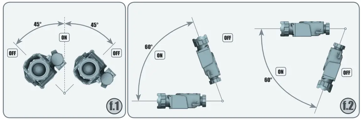
5.2.2 .4 Standby![]()
Rather than turning the device off, the user could choose the Standby function. In this condition, the device passes into a low-power consummation state and switches off the display, the module, and other peripheral hardware, every time when the tilt angle is more than 45° to both sides (fig. 1) and 60° upwards and downwards (fig. 2).
As soon as these conditions are not fulfilled, or any key is pressed, the device will automatically switch on.
When the Standby function is active, the mode-corresponding icon appears in the upper right corner and it is visible permanently. The icon indicates the active user selection
The On/Off function is visualized with an ![]() or a check mark
or a check mark ![]() above the main icon.
above the main icon.
Activating/deactivating of the function is done by briefly pressing the ![]() button.
button.
5.2.3.1 NUC Shutter Settings![]()
5.2.3 Settings ![]()
Through the menu the user has access to three modes of calibration of the microbolometer and the sensor of the device. We recommend the use of Automatic mode, in which the calibration frequency depends on the temperature characteristics of the sensor.
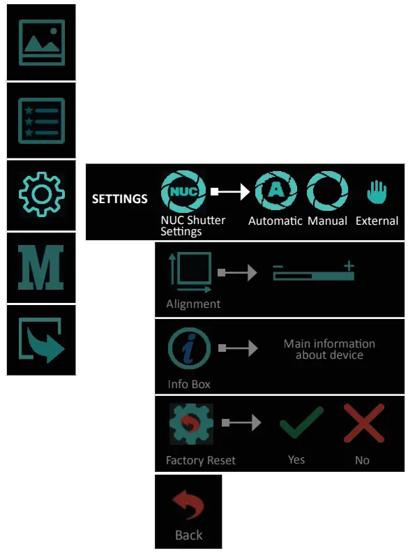
- Automatic mode – The calibration is performed automatically at regular intervals and with a shutter mechanism located in the device.
![]() IMPORTANT!
IMPORTANT!
The factory NUC settings of the device are in Automatic mode!
- Manual mode – The calibration is performed by the user, by pressing and holding the button for more than 2 seconds, at desired intervals, with a shutter mechanism located in the device. It is not necessary for the user to cover the lens with an external barrier.
- External mode – The calibration is performed by the user, by pressing the button, at desired intervals, with an external lens barrier, which can be a hand or the protective cap of the lens. The user must eliminate the entry of energy through the lens to the sensor of the device. Calibration without closing the lens will create a “ghost” effect in the image.
![]() IMPORTANT!
IMPORTANT!
In manual and external calibration mode (NUC), the pictogram for the respective is permanently displayed.
When the user switches to Auto NUC from some other calibration mode, the icon appears on the display for 5 seconds and then disappears.
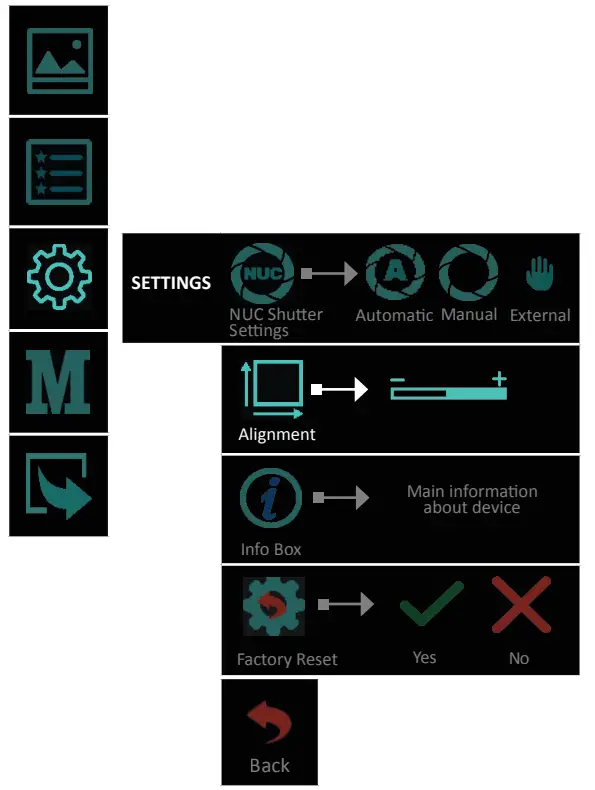
5.2.3.2 Alignment![]()
With Alignment function, you can precisely align the optical axis of the day sight and the clip-on attachment. The manufacturing process of the device ensures the shooting precision tolerance up to 5 cm at 100 m. By this Alignment function, you can achieve much better accuracy.
Entering the Alignment function allows shifting the image in all directions to align it to the day scope zero, The X and Y values showing the current position of the image and If the impact point is different than the center point of the day scope, the image should be moved in a direction opposite of the impact point by changing the X and Y values (up/down or left/right).
The action is performed with the ![]() (up/right) and
(up/right) and ![]() (down/left) buttons.
(down/left) buttons.
Switching between directions is performed by short pressing the ![]() button.
button.
Move the image so that the point of impact matches with the center point of the day scope. Example: If the impact point is right below the impact point of the day scope, the
image should be moved up and left.
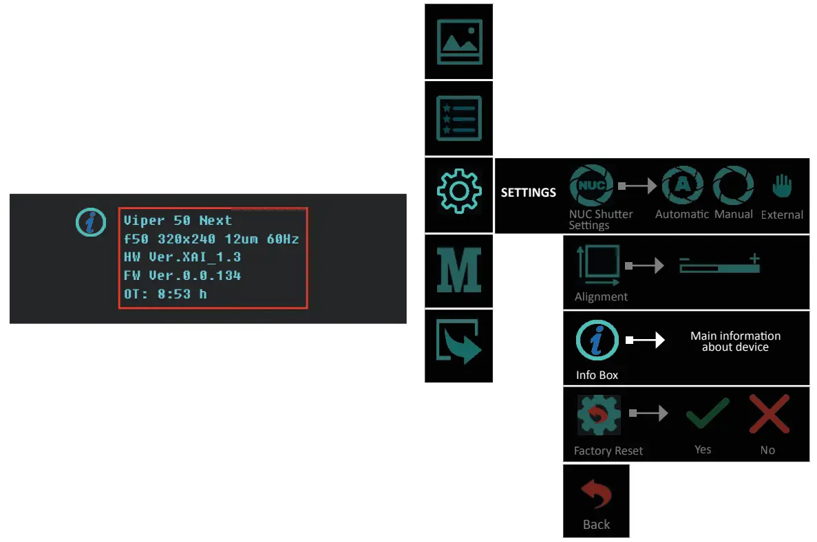
5.2.3.3 Info Box![]()
The customer can get up-to-date information about the device, such as main technical characteristics and firmware information.
In Info Box is shown and the actual operating time of the device.
![]() 5.2.3.4 Factory Reset
5.2.3.4 Factory Reset
By selecting and confirming this feature all factory settings of the device are restored, including the alignment of the front attachment. During the factory reset process, the user receives information about the progress on the display.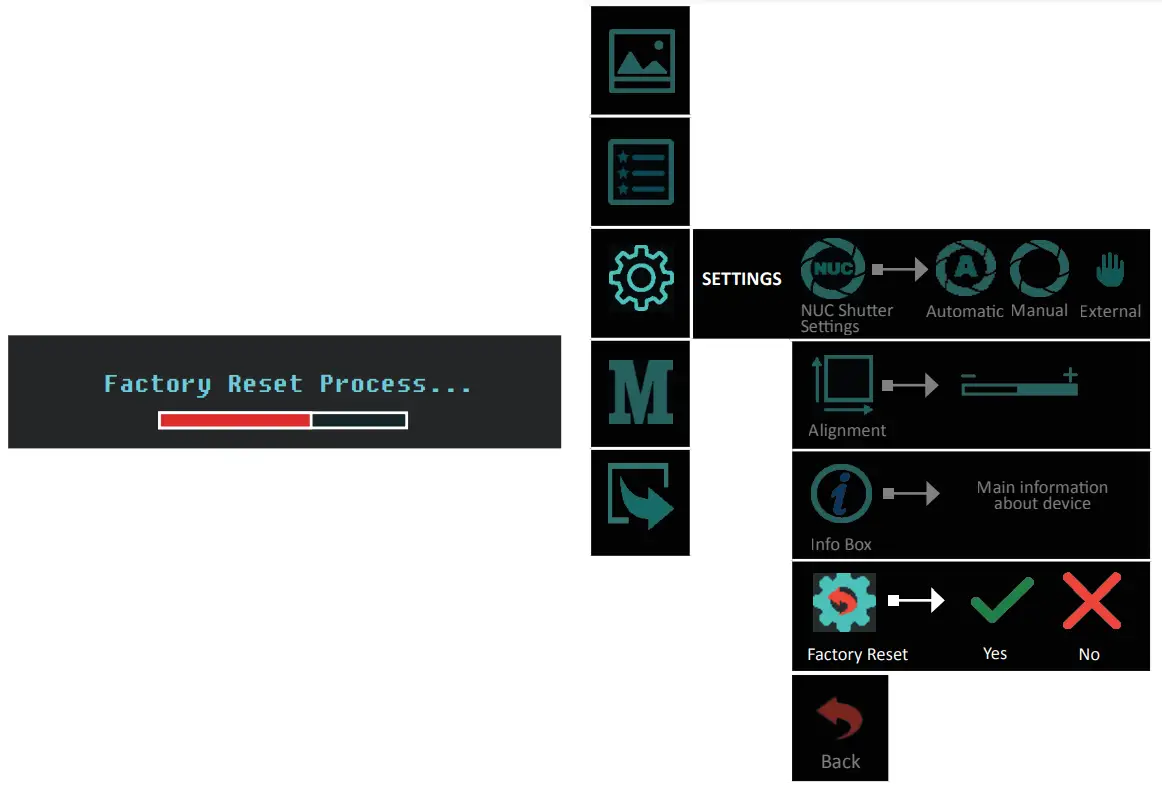
![]() ATTENTION!
ATTENTION!
By performing the Factory Reset procedure, you will delete all the settings saved on the device, including the alignment with the day optical sight!
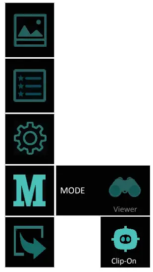
5.2.4 Mode
To use Viper 50 Next as a clip-on device select Mode>Clip-On![]() from the menu. All important On-screen elements are displayed in the central area of the image. The reason is the reduced field of view of the daysight by higher magnifications. For a larger and scalable image and to facilitate the operating with the menu during the initial individual adjustment, please switch to observation mode.
from the menu. All important On-screen elements are displayed in the central area of the image. The reason is the reduced field of view of the daysight by higher magnifications. For a larger and scalable image and to facilitate the operating with the menu during the initial individual adjustment, please switch to observation mode.
Quick function for switching between observation and clip-on mode: hold down the button![]() and the
and the ![]() button simultaneously. The pictogram for indication of the respective ode appears in the center of the image for 2 seconds.
button simultaneously. The pictogram for indication of the respective ode appears in the center of the image for 2 seconds.
When reaching a low battery state the device gives a warning in the top left corner of the central area. There is a possibility to ignore it by pressing the ![]() button.
button.
![]() NOTE
NOTE
It is recommended to use up to 3X magnification of the primary optical unit in order to keep the menu and all submenus visible in clip-on mode.
![]() NOTE
NOTE
In Clip-on mode the digital zoom is locked. The![]() button calls up the Infobox, which gives information about the current settings of the device.
button calls up the Infobox, which gives information about the current settings of the device.
BATTERY USE
6.1 Battery replacement
The device is powered through 1 piece of 18650 Li-Ion rechargeable battery.
The battery replacement instructions are presented below.
Please remove the protective rubber lens cap before opening the battery compartment and replacing the battery.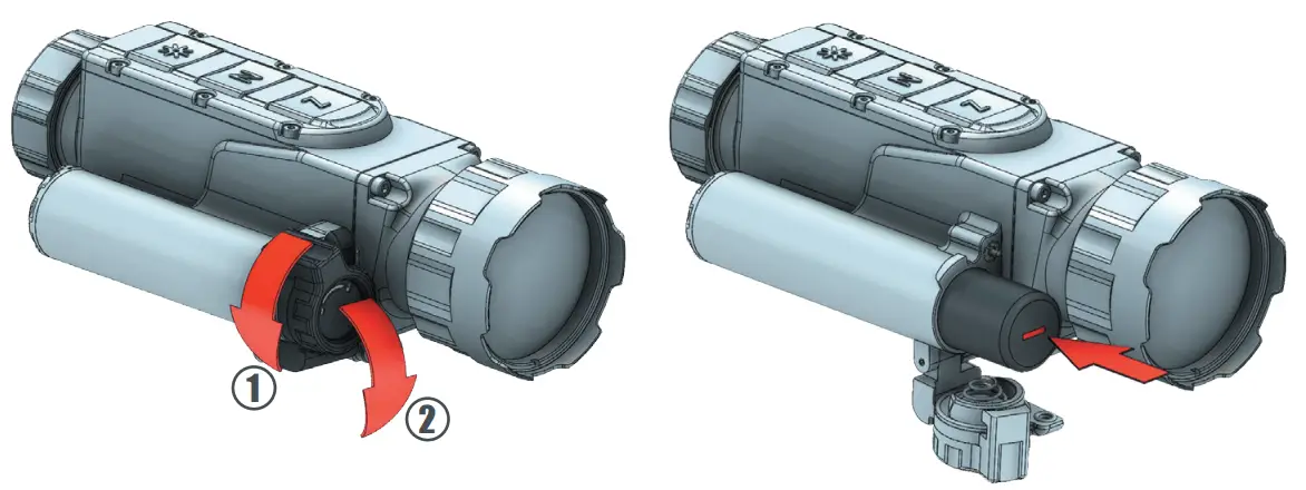
![]() NOTE
NOTE
Attempting to power on the device, when the battery is fully depleted, will cause a red indicator to blink for a few seconds.
![]() IMPORTANT!
IMPORTANT!
Always place the battery using the correct battery orientation (shown in the battery holder) to avoid damaging the device.![]() NOTE
NOTE
The batteries are not covered by the warranty!![]() IMPORTANT!
IMPORTANT!
Please keep all batteries away from moisture.
![]() NOTE
NOTE
Make sure the device is turned off before replacing the battery.
6.2 Tips for proper battery care and use
- Use the correct size and type of battery specified in the technical description and user manual.
- Keep the battery contact surfaces and the battery compartment contacts clean. For this purpose you can use a clean pencil rubber or a rough cloth each time you replace the battery.
- Remove the battery from the device when in storage for a longer period of time.
- Make sure that you insert the battery into your device properly (with the + (plus and – (minus) in the correct position). Store batteries in a dry place at normal room emperature.
- Extreme temperatures reduce battery performance.
- Do not attempt to recharge a battery, unless it is specifically marked as “recharge- able.”
6.3 Battery charging
![]() ATTENTION!
ATTENTION!
Only recharge the batteries provided in the delivery set!
Note the polarity of the batteries when placing them in the charger.
The battery charger is equipped with a led indicator for each battery slot that will display the current charge of the inserted battery.
The indicator will blink while the charging process is not completed and will turn a solid yellow color when it is complete.
Incorrectly placed batteries will cause all three slot indicators to blink.
Should this occur, correct any wrongly placed batteries to resume the charging process.
 Charger for RCR123 A and 18650 Li-Ion rechargeable batteries
![]() ATTENTION!
ATTENTION!
Do NOT insert more than one battery in each slot.![]() NOTE
NOTE
The battery charger is not covered by the warranty!
ATTACHMENT
7.1 Installation in front of the daytime rifle scope
![]() NOTE!
NOTE!
During shooting with the clip-on thermal device Viper 50 Next attached to the daytime rifle scope with help of the fixed adapter. The adapter could move along the daytime rifle scope. The size of this movement depends on the tightening force of the locking thumb and recoil force of the weapon and could be equal to 1 mm on each shot. This movement is allowed and does not affect the impact point. The position of the adapter should be controlled after each shot in the shooting sequence.
![]() NOTE
NOTE
Always check and make sure that the counter ring providing with the Viper 50 Next device is tightened to the adapter securely and ensures the thread and the connection adapter-device firmly enough.
![]() TIp
TIp
Mark both – the clip-on and the daytime rifle scope and check markers for displacement fter each shot.![]() WARNING!
WARNING!
Use of this device may be restricted by national regulations. You should consult with local authorities prior to using the clip-on thermal device Viper 50 Next.
![]() NOTE
NOTE
Images used in the following instructions are for illustrative purposes only. Diameter and the appearance of the counter ring may vary due to the diameter of the used daytime ifle scope and the manufacturer of the counter ring.
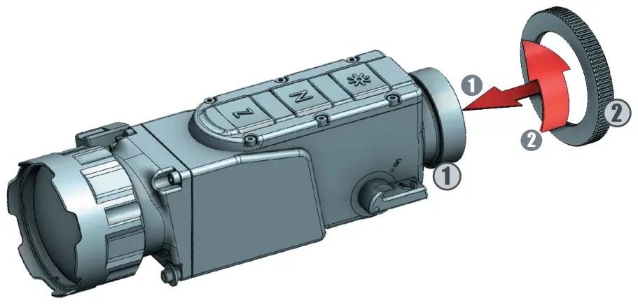
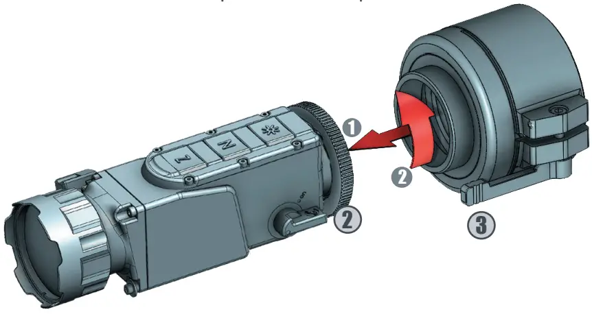
Mount your clip-on thermal device in front of the daytime rifle scope as follows
- Turn the counter ring 2 clockwise and screw it into the thread 1 , located on the back side of the device until stops.

- Turn the fixed counter ring 3 clockwise and screw it on the inner thread of the counter ring 2 . Tight the counter ring to the adapter and ensure the connection between he adapter and the Viper 50 Next device is securely.
 Position the clip-on thermal device to the daytime rifle scope with the control buttons located on top. Put the clip-on thermal device with the fixed adapter on the front of the daytime rifle scope 4 and fix it with the adapter thumb 5 .
 Position the clip-on thermal device to the daytime rifle scope with the control buttons located on top. Put the clip-on thermal device with the fixed adapter on the front of the daytime rifle scope 4 and fix it with the adapter thumb 5 .
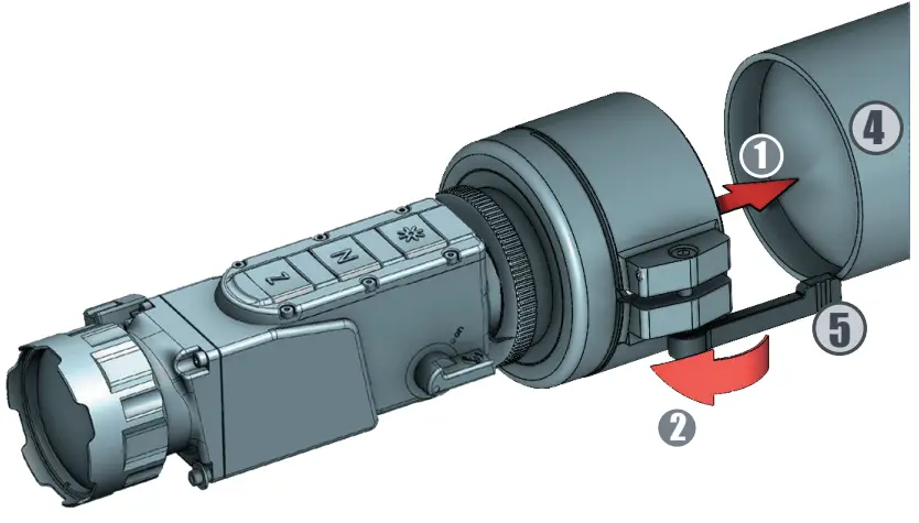
OPERATING WITH THE DEVICE
The advantage of being mounted in front of a daytime rifle scope is that the clip-on thermal device does not affect the rifle scope zero and keeps all tactical features of a
daytime rifle scope intact.
After attaching the clip-on thermal device Viper 50 Next to the daytime rifle scope follow the next steps for operation with the device:
- Always check the adjustment of the daytime rifle scope (diopter adjustment, parallax, adjustment, etc.)
- witch on the device.
- Make sure the device is in clip-on mode.
3. Set the required magnification of the daytime rifle scope. Choose the object of observation and focus the objective lens of the device by using the lens focusing ring of the front of the objective. - The fire adjustment of the system that includes both the daytime rifle scope and Viper 50 Next clip-on thermal device should be performed in accordance with the nstructions for adjustment of the daytime rifle scope.
- Turn off the device after use and remove the battery from the compartment to avoid battery leakage.
![]() NOTE!
NOTE!
When mounted in front of the daytime rifle scope Viper 50 Next can change zeroing no more than 5 cm. This is connected to changes in the weapon balance, light distortions in the daytime rifle scope, and technological limits of the adjustment of the Viper 50 Next clip-on thermal device.![]() NOTE!
NOTE!
For maximum image quality through the daytime rifle scope, we recommend using a rifle scope magnification up to 3x.
STORAGE
To maximize the life of your device and to protect it from damage we recommend stor- ing it in the individual packaging in which you received it.
Before storing it, be sure to clean the device (remove any moisture, dust or traces of dirt)!
Make sure that the battery compartment is empty and there aren’t any traces of moisture in it.
For shorter periods of time, the device can be safely stored in a suitable soft bag or a cartridge box.
The premises in which the device is kept for long term have to be dry, enclosed, unheated and ventilated.
When storing the device for a longer period of time, make sure that it is kept in a dry, enclosed, unheated and ventilated space. Do not subject the device to excessive temperatures outside the range of [-30:50°C], relative humidity that is greater than 80% and long periods of direct sunlight.
TRANSPORTATION
We recommend that the product be transported only with its original packaging
Before each transportation, the product should be neatly packed in its original packaging (transport bag) and all other items and accessories should be carefully and securely placed in the transport box.
PRODUCT DESCRIPTION AND PRINCIPLE OF OPERATION
We recommend that the product be transported only with its original packaging.
Before each transportation, the product should be neatly packed in its original packaging (transport bag) and all other items and accessories should be carefully and securely
placed in the transport box.
11.1 Product description
The Viper 50 Next device allows detection of objects that emit energy in the infrared spectrum. The equipment can operate in rain, fog and total darkness in a completely passive mode (without additional illumination). The active matrix is microbolometer, working in the wavelength range from 7 to 14 μm. The unique design of the device makes it reliable and ergonomic.
The body is made of strong, ultra-lightweight magnesium alloy and has been applied with matt anti-reflective coating. The device’s functions can be accessed through the buttons, while the OSD (on-screen-display) provides status information about it’s current condition.
11.2 Principle of operation
Thermal cameras detect temperature by recognizing and capturing different levels of infrared light. This light is invisible to the naked eye, but can be felt as heat if the intensity is high enough.
All objects emit some kind of infrared radiation, and it’s one of the ways that heat is transferred. If you hold your hand over some hot coals on the grill, those coals are emitting a ton of infrared radiation, and the heat is transferring to your hand. Furthermore, only about half of the sun’s energy is given off as visible light—the rest is a mix of ultraviolet and infrared light.
The hotter an object is, the more infrared radiation it produces. Thermal cameras can see this radiation and convert it to an image that our eyes can see.
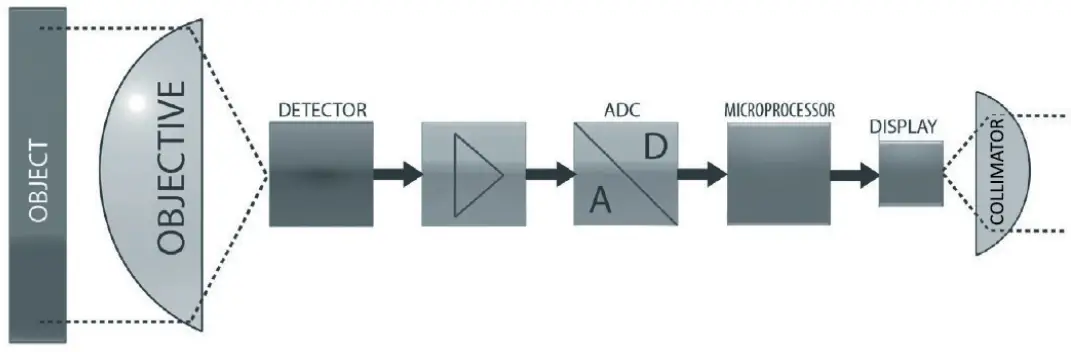
A special germanium objective lens focuses the infrared energy emitted by all of the objects in field of view of the device. The focused radiation is scanned by an array of infrared-detector elements. The detector elements create a detailed temperature pattern of the observed scene called a thermogram. The signal generated by the detector elements is passed through an analog-to-digital converter and translated into discrete electric impulses. The impulses are sent to an image-processing unit, a circuit board with a dedicated chip that improves the image quality and converts the information from the elements into data for the display. The signal-processing unit sends the information to the display, where it is displayed as a different shade of gray depending on the intensity of the infrared emission. The combination of the impulses from all of the detector’s elements creates the final image.
TROUBLESHOOTING
| TYPICAL FAULTS AND THEIR EXTERNAL SIGNS | POSSIBLE CAUSES | POSSIBLE SOLUTIONS |
| When the device is turned on there is no image on the screen | – Poor contact with the bat- teries – Wrong battery polarity – Depleted battery – Display brightness is set to minimum – Problem with the battery cap – Display problem – Detector problem | – Check batteries and battery compartment contacts and clean them, if necessary with the cleaning cloth. Replace or recharge the batteries – Adjust the brightness through the menu – Replace the battery cap – Return the device for maintenance |
| The image of the area is weak and foggy | – Contamination over the external surfaces of the objective and/or the eyepiece/col- limator – Contamination of the internal surfaces of the objective and/ or the eyepiece/collimator | – Clean all external surfaces with a napkin or the LensPen – Return the device for maintenance |
| The image is smudged/ negative like image | – NUC is on external mode – NUC mechanism is stuck | – Cover the lens by hand and press the N button or switch to internal NUC and press the N button – If on internal NUC the mechanics do not move when pressing the N button (you do not hear acoustic click), return the unit to the factory for maintenance. |
| The image is smeared or grainy | – Wrong weather type or im- age filter is selected | – Try other image filters or weather types until you reach the desired Image appearance |
| The panel buttons do not function | – Electronics boot failure – Electronics malfunction | -Restart the device – Return the device for maintenance |
| The Auto NUC is not working | – External NUC mode is se- lected – Shutter is stuck | – Switch to internal NUC and press N button – Return the device for maintenance |
| The ZOOM is not working | – Clip-on mode is selected (if applicable) – Electronics boot failure Electronics malfunction | – Select monocular mode (if applicable) – Restart the device – Return the device for maintenance |
| The image on the display is blurred and out of focus | – Device is not focused on the observed distance – The eyepiece/collimator back lens are dirty – Opto-mechanical malfunction | – Focus on the target object – Clean the collimator lens _ Return the device for maintenonce |
| There are fewer or no details in the image and there is too much exposure of the object | _ Contrast level is high | – Decrease Contrast level |
| The scene back- ground is too dark | – Low Contrast level – Low Brightness level | – Increase Contrast level – Increase Brightness level |
| The image is too dark | – Low Luminance level – Low Brightness level | – Increase display Luminance level – Increase Brightness level |
| The dip-on goes off when shooting | – Poor contact with the bat-teries – Problem with the battery cop – Display problem | – Check batteries and battery compartment contacts and clean them, if necessary, with the cleaning cloth. Replace the batteries. – Check that the battery cap is tightly closed – Return the device for maintenance |
| There is a shift of point the impact relative to the daily sight scope | – Incorrectly parallax adjust- ment of the daily optic sight – Improper attachment of the ,. cisp-on to the daily optical sight – Ammunition changed – The clip-on needs additional adjustment | -Set the parallax correctly of the daily optic sight – Check the attachment of the clip-on to the daily optical sight – Check your ammo – Make additional adjustments with the alignment function |
| There are defective pixels on the display | – Damage in the microbolom- eter array caused by shooting or other mechanical impacts | – Correct defective pixels with the MBPR function in settings or use Auto BPR function |
| There is a ghost effed on the image | The device is in calibration mode of the sensor with an external barrier (external NUC mode), and access of light through the lens to the sensor is not blocked by a hand or cop during the NUC procedure. | – Block the access of light through the lens to the sensor by hand or cop during NUC procedure. – Switch to AUTO NUC mode |
TECHNICAL PARAMETERS
| FOCAL PLANE ARRAY (FPA) | |
| Type | Microbolometer |
| Pixel Count (Resolution) | 320×240 |
| Pitch Size | 12 pm |
| Spectral Response | 7 ÷14 pm |
| Thermal Sensitivity (NETD) | < SO mK @ F/ 1.0 |
| THERMAL IMAGING PERFORMANCE | |
| Brightness/Contrast | Automatic/Advanced Image Processing |
| Image Polarity | User Selectable (White Hot/ Black Hot/Red Hot/Isotherm) |
| Menu | Dropdown Menu / OSD |
| IFOV | 0.24 mrad |
| NUC | Automatic / Manual/External |
| OPTICS | |
| Focal Length of the Objective Lens | 50 mm |
| FOV | 4.4°(H) X 3.3°(V) |
| F/# | 1.2 |
| Material & Coating | Germanium, Hard Carbon Coating on the External Surface |
| VIDEO | |
| Digital Zoom | x2, x4 |
| Frame Rate | 60 Hz progressive |
| Viewfinder Luminance | Manual via OSD |
| POWER | |
| Power Source | 1 x 18650 LI-Ion rechargeable |
| Operating Times | Up to 5 hours with 1 x 18650 Li-Ion @ 25°C |
| STATIC RANGE PERFORMANCE Calculated Apr geometrical average NOTE: The distances defined are calculated in geometrical values only, not accounting the atmospheric conditions. | |
| Human Detection Range (human figure 1.8×0.5m) | 1980 m |
| Human Recognition Range (human figure 1.8×0.5m) | 660 m |
| ENVIRONMENTAL CHARACTERISTICS | |
| Operating Temperature Range | -25°C to +50°C |
| Storage Temperature Range | -30°C to +55°C |
| Mechanical Vibration | Sinusoidal, 40 m/s2, 10 to 80 Hz |
| Index of Protection | IP 66 |
| PHYSICAL CHARACTERISTICS | |
| Dimensions Hx WxL | 157x 54x 71mm |
| Weight – without battery – with battery | 295 g 340 g |
ANMERKUNGEN
NOTES
Website:
https://nitehog.com/
Youtube:
Nitehog Europe GmbH
Facebook:
https://www.facebook.com/NitehogEuropeGmbH
Instagram:
https://www.instagram.com/nitehog/
Contacts:
Pistoriusstrasse 6A, 13086 Berlin, [email protected]
+49 (0) 30 / 9606 670 220
![]()


