Befaco SYN0007992-000 Noise Plethora Complex Noise Generator
POWER & INTRO
POWERING THE MODULE
THANKS FOR PURCHASING A MODULE FROM BEFACO!BEFORE YOU PLUG THIS MODULE IN…
- Disconnect your cabinet from the mains.
- Triple check the power cord polarity. The coloured line on the cable (pin number one) is the -12V rail.
- If you plug the module backwards you might burn it out and unfortunately this is not covered by the warranty.
- If you have any questions about this product feel free to contact us [email protected]

INTRODUCTION
WHAT IS NOISE PLETHORA?
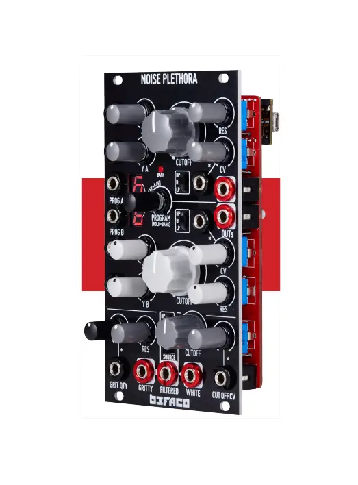
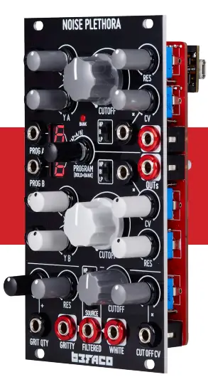
Noise Plethora is an Eurorack Noise Workstation in 14HP. The module consists in three digital sounds generators equipped with an Analog Multimode Filter to sculpt the sound and generate any kind of textures and noises.
MODULE STRUCTURE
GENERATORS
- GENERATOR A
Digital Noise algorithms Analog multimode filter - GENERATOR B
Digital Noise algorithms Analog multimode filter - GENERATOR C
- White Noise and Granular “Gritty Noise”
- Analog multimode filter
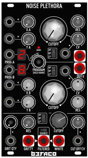
CONTROLS
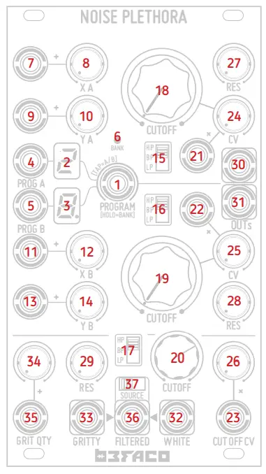
- 1. Manual Program/Bank Selector
Programs are organized in banks of 10 programs each (0…9) Turn it to select the programs.
Toggle between Generator A and B by pushing it quickly. Hold it for 1 second to access Bank selection (Bank LED will blink). Select the bank same way you select a program.
To come back to Program selection just hold it for 1 second again.
After a couple of seconds of inactivity on this control, the selection is saved to the internal non-volatile memory. - 2/3. Program/Bank Display
- Shows the current Program or Bank.
- The dot at the bottom right corner of the display shows which Generator is selected.
- 4/5. Program Select CV Ins
Select between programs on the selected Bank. - 6. Bank LED Indicator
It lits during Bank selection. - 7/8/11/12. “X” Controls (Generator A and B).
The voltage applied to “X” CV Input is summed to the value present at “X” manual control.
CV Input Range: 10Vp-p. Higher voltages will be ignored. - 9/10/13/14. “Y” Controls (Generator A and B)
- The voltage applied to “Y” CV Input is summed to the value present at “Y” manual control.
- CV Input Range: 10Vp-p. Higher voltages will be ignored.
- 15/16/17. Filter Mode Selectors
Switch between Low-Pass, Band-Pass and High-Pass mode. - 18/19/20. Filter Cutoff Frequency Control.
- 21/22/23. Filter Cutoff CV Inputs.
The voltage applied to those Inputs is summed to the value present at the Cutoff manual control.
Input Range: 10Vp-p - 24/25/26. Filter Cutoff CV Attenuators.
Attenuators for Cutoff CV Inputs. - 27/28/29. Filters Resonance Control.
- 30/31. Main Outputs for Generators A and B
- 32. White Noise Output.
- 33. Gritty Noise Output.
- 34/35. Gritty Noise “Grit” Quantity.
The voltage applied to “Grit Qty” CV Input is summed to the value present at “Grit Qty” manual control. CV Input Range: 10Vp-p - 34/35. Gritty Noise “Grit” Quantity.
The voltage applied to “Grit Qty” CV Input is summed to the value present at “Grit Qty” manual control. CV Input Range: 10Vp-p
MISCELLANEA
- SPECS
- Size: 14HP
- Deeth: 30 mm
- +12v: 65 mA
- -12v: 8mA
- CREDITS
- This module is the result of loads of hours of work, love, and care.
- It would have been impossible to finish without the help of beta testers, loving friends, fearless programmers, and the whole Befaco conclave of opinionologist.
- Hardware design, documentation, user interface, and sound design by Befaco team.
- Beta testing by Jose Cabrera, Sam Gerber, Miguel Eedl, and the Befaco team.
- Firmware coding by Jeremy Bernstain, Julia Mugica, Ivan Paz, and Befaquers.
BE SURE YOU HAVE THE LATEST FIRMWARE INSTALLED
- The firmware version will display shortly at startup.
- Example of a display showing 1.1 version
- If your Noise plethora is not updated please download the firmware from “https://Befaco.org/noise-plethora” and follow the install
instructions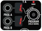
PROGRAMS
| BANK: A – TEXTURES | |||
| CV1 | CV2 | ||
| 0 | RadioOhNo | Four Square wave Oscillators cross Moded in couples and added together. | |
| OSC 1 Frequency | OSC 2 Frequency + PWM | ||
| 1 | Rwalk_SineFMFlange | Four random walkers in a box of size L mapped to the frequencies of Pulse oscillators, modulated by sine FM synth and filtered by a flange effect. | |
| Modulation Frequency | Flanger | ||
| 2 | xModRingSqr | Cross FM Between Two square wave Oscillators. The out is the ring modulation of the two. | |
| OSC 1 Frequency | OSC 2 Frequency | ||
| 3 | xModRingSine | Cross FM Between Two sine wave Oscillators. The out is the ring modulation of the two. | |
| OSC 1 Frequency | OSC 2 Frequency | ||
| 4 | CrossModRing | 4 waves FMing each other in a daisy chain and the last one FMing the first one. All outs are multiplied together. | |
| Freq (different ratios each) | FM Index | ||
| 5 | Resonoise | Square wave FM-ing a sine wave. The result is passed through a wave folder and a BPF. The filter cutoff is modulated by white noise. | |
| Both waves Freqency | Folding amount | ||
| 6 | GrainGlitch | Square Wave sent through a granular cell. The out of this cell is feedback to the Oscillator as FM. The out is a combination of the oscillator and the granular cell using XOR logic gate. | |
| Square Wave frequency | FM Index and grain size | ||
| 7 | GrainGlitchIII | Square Wave sent through a granular cell. The out of this cell is feedback to the Oscillator as FM. The out is taken from the granular cell. | |
| Square Wave frequency | FM Index and grain size | ||
| 8 | GrainGlitchIII | Sawtooth Wave sent through a granular cell. The out of this cell is feedback to the Oscillator as FM. The out is taken from the granular cell. | |
| Square Wave frequency | FM Index and grain size | ||
| 9 | Basurilla | 3 Withe Noise generators gated by 3 independent Pulse LFOs | |
| LFOs Frequency | LFOs Pulsewidth | ||
| BANK: B – HH CLUSTERS | |||
| CV1 | CV2 | ||
| 0 | ClusterSaw | 16 Sawtooth Oscillators with adjustable linear frequency relation | |
| Frequency | Spread | ||
| 1 | PwCluster | 6 Detuned pulse waveforms with adjustable pulse width | |
| Frequency | Pulsewidth | ||
| 2 | CrCluster2? | 6 detuned Sine Waves with low-frequency FM | |
| Frequency | FM Index | ||
| 3 | SineFMcluster | 6 detuned sine waves, frequency modulated by 6 independent sine modulators. | |
| Frequency | FM Index | ||
| 4 | TriFMcluster | 6 detuned triangle waves with frequency modulated by 6 independent sine modulators. | |
| Frequency | FM Index | ||
| 5 | Primecluster | 16 sawtooth waves detuned using prime numbers, with a common Sine Frequency Modulator. | |
| Frequency | FM Index | ||
| 6 | PrimecCnoise | 16 Triangle Waves detuned using prime numbers, frequency modulated by white noise. | |
| Frequency | FM Index | ||
| 7 | FibonacciCluster | 16 sawtooth detuned using Fibonacci series, and each frequency is multiplied by a “spread” Factor. | |
| Frequency | Spread Factor | ||
| 8 | PartialCluster | 16 sawtooth, detuned by multiplying each of the frequencies by a “spread” Factor. | |
| Frequency | Spread Factor | ||
| 9 | PhasingCluster | 16 Square Waves detuned by multiplying each of the frequencies by a “spread” Factor, with an LFO detuning all of them slightly. | |
| Frequency | Spread Factor | ||
| BANK: C – HARSH & WILD | |||
| CV1 | CV2 | ||
| 0 | BasuraTotal | “Bent” LFSR using FM on an oscillator with reverb. | |
| LFSR Speed | Reverb Amount | ||
| 1 | Atari | Two Square waves with PWM/FM cross Modulation. The first one do PWM to the second, and the second do FM to the first. | |
| Wave 1 Freq | Wave 2 freq + FM Index | ||
| 2 | WakingFilomena | 16 random walkers mapped to the frequencies of Pulse oscillators in an L-size box. | |
| L box lenght | FM Index | ||
| 3 | P_S_H | Noise trough Sample & Hold + Dirty Reverb. | |
| S&H Rate | Reverb Amount | ||
| 4 | ArrayOnTheRocks | FM patch where modulator is a sine wave and the carrier a wavetable with some values of the table been randomized on the fly. | |
| Carrier Frequency | Modulator Frequency | ||
| 5 | ExistencelsPain | Sample & Hold Noise through four bandpass filters whose frequency is controlled by four triangle oscillators. | |
| Sample & Hold Rate | BPF CutOff Mod-Index | ||
| 6 | WhoKnows | Pulse Wave trough four band pass filters whose frequency is controlled by four triangle oscillators. | |
| Pulse Frequency | BPF CutOff Mod-Index | ||
| 7 | SatanWorkout | White Noise FM-ing a sine wave. The result is downsampled and distorted. | |
| Frequency + FM index | Sample Rate | ||
| 8 | Rwalk_BitCrushPW | Nine random walkers in a box of size L mapped to nine waveforms frequencies, and a bit crusher filter mapped to their pulse-width. The result Is passed through reverb. | |
| L box length | Reverb Roomsize | ||
| 9 | Rwalk_LFree | Four Pulse Width Modulated Pulse waveforms with reverb. | |
| L box length | Reverb Roomsize | ||


