Shuttle DH410 Robust 1.3-litre Slim PC
 Product Overview
 Product Overview
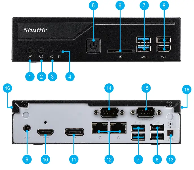
- MIC-in (Option)
- Headphones (Option)
- Power LED
- Hard Disk Drive LED
- Power Button
- SD Card Reader (Option)
- USB 3.2 Gen 1 Ports
- USB 2.0 Ports
- Power Jack (DC IN)
- HDMI 2.0 Port
- DisplayPort
- LAN Ports
- Clear CMOS & Power Button & +5V
- COM 1 Port (RS232/RS422/RS485)
- COM 2 Port (RS232 only)
- Kensington® Lock Hole
Hardware Installation
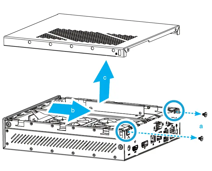
Begin Installation
NOTE: For safety reasons, please ensure that the power cord is disconnected before opening the case.
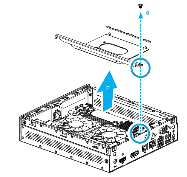
- Unscrew the two screws of the chassis cover. Slide the cover backward and upwards.

- Unfasten the rack mount screw and remove the rack.

The product’s color and specifications may vary from the actual shipping product.
CPU and ICE Module Installation
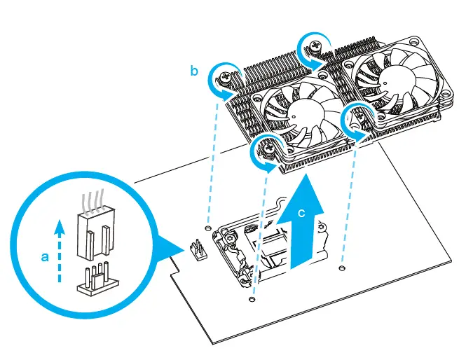
- Unfasten the four ICE module attachment screws and unplug the fan connector. Remove the ICE module from the chassis and put it aside.

Follow the steps below to correctly install the CPU into the motherboard CPU socket.
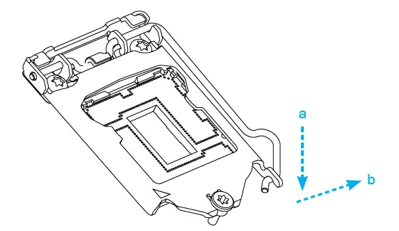
Note: This CPU socket is fragile and can easily be damaged. Always use extreme care when installing a CPU and limit the number of times you remove or change the CPU. Before installing the CPU, make sure to turn off the computer and unplug the power cord from the power outlet to prevent damage of the CPU. - Unlock and raise the socket lever.

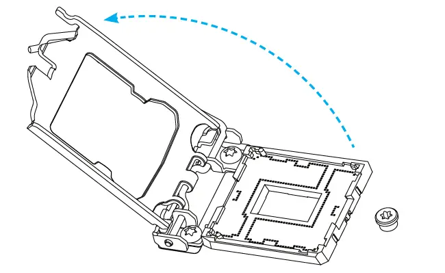
- Lift the metal load plate on the CPU socket.

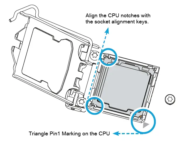
DO NOT touch the socket contacts. To protect the CPU socket, always use the protective socket cover when the CPU is not installed. - Please orientate the CPU correctly and align the CPU notches with the socket alignment keys. Make sure the CPU sits perfectly horizontal, then push it gently into the socket.

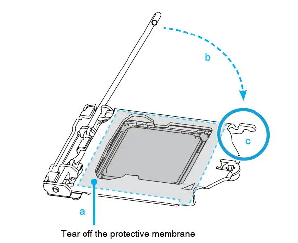
Note: Please be aware of the CPU orientation, DO NOT force the CPU into the socket to avoid bending of pins on the socket and damage of CPU! - Tear off the protective membrane from the metal load plate. Close the metal load plate, lower the CPU socket lever and lock in place.

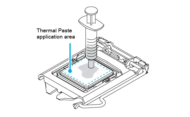
- Spread thermal paste evenly on the CPU surface.

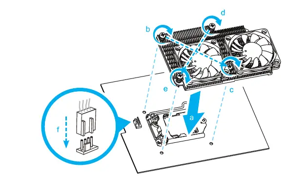
Note: Please do not apply excess amount of thermal paste. - Screw the ICE module to the motherboard. Note to press down on the opposite diagonal corner while tightening each screw.
- Connect the fan.

Memory Module Installation
This motherboard does only support 1.2 V DDR4 SO-DIMM memory modules.
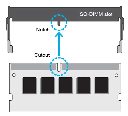
- Locate the SO-DIMM slots on the motherboard.
- Align the notch of the memory module with the one of the relevant memory slot.

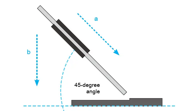
- Gently insert the module into the slot in a 45-degree angle.
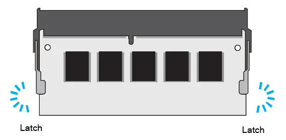
- Carefully push down the memory module until it snaps into the locking mechanism.


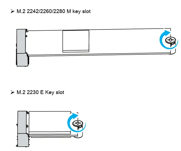
M.2 Device Insatallation
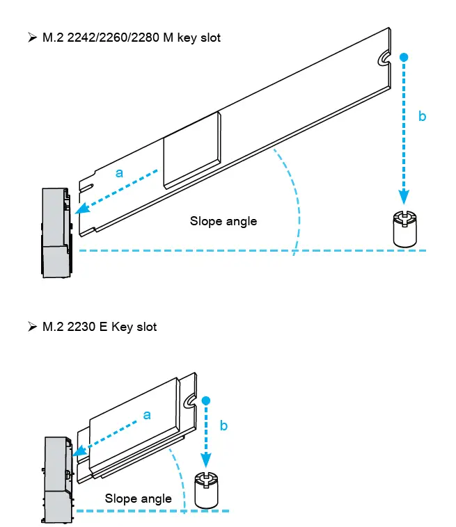
- Locate the M.2 key slots on the motherboard.

- Install the M.2 device into the M.2 slot and secure with the screw.

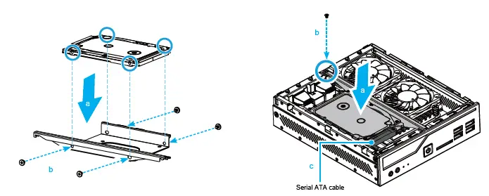
HDD or SSD Installation
- Place an HDD or SSD in the rack and secure it with the four screws from the sides.

- Slide the rack back into the chassis and refasten the screws. Connect the Serial ATA cable to the HDD or SSD.
Complete
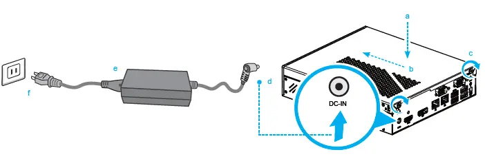
- Please replace and affix the case cover with two screws, then connect the power cord.
- Complete.

Note: Please press the “Del” key while booting to enter BIOS. Here, please load the optimised BIOS settings.
Safety Information
Incorrectly replacing the battery may damage this computer. Replace only with the same or equivalent as recommended by Shuttle. Dispose of used batteries according to the manufacturer’s instructions.
This device complies with Part 15 of the FCC Rules. Operation is subject to the following two conditions: (1) this device may not cause harmful interference, and (2) this device must accept any interference received, including interference that may cause undesired operation.|
This device meets the requirements for the EU conformity in accordance to the currently valid EU directives.
Product Overview
- MIC-in (Option)
- Headphones (Option)
- Power LED
- Hard Disk Drive LED
- Power Button
- SD Card Reader (Option)
- USB 3.2 Gen 1 Ports
- SB 2.0 Ports
- Power Jack (DC IN)
- HDMI 2.0 Port
- DisplayPort
- LAN Ports
- Clear CMOS & Power Button & +5Vv
- COM 1 Port (RS232/RS422/RS485)
- COM 2 Port (RS232 only)
- Kensington® Lock Hole
Hardware Installation
Begin Installation
For safety reasons, please ensure that the power cord is disconnected before opening the case.
- Unscrew the two screws of the chassis cover. Slide the cover backwards and upwards.
- Unfasten the rack mount screw and remove the rack.
CPU and ICE Installation
- Unfasten the four ICE module attachment screws and unplug the fan connector.
Remove the ICE module from the chassis and put it aside.
Follow the steps below to correctly install the CPU into the motherboard CPU socket. - Unlock and raise the socket lever.
- Lift the metal load plate from the CPU socket.
Note: DO NOT touch the socket contacts. To protect the CPU socket, always use the protective socket cover when the CPU is not installed. - Please orientate the CPU correctly and align the CPU notches with the socket alignment keys. Make sure the CPU sits perfectly horizontal, then push it gently into the socket.
- Carefully push down the memory module until it snaps into the locking mechanism.
- Repeat the above steps to install an additional memory module, if required.
M.2 Device Installation
- Locate the M.2 key slots on the motherboard.
- 2. Install the M.2 device into the M.2 slot and secure with the screw.
HDD or SSD Installation
- Place an HDD or SSD in the rack and secure with the four screws from the sides.
- Slide the rack back into the chassis and refasten the screws. Connect the Serial ATA cable to the HDD or SSD.
Complete
- Please replace and affix the case cover with two screws, then connect the power cord.
- Complete.
Note: Please press the “Del” key while booting to enter BIOS. Here, please load the optimised BIOS settings.
Motherboard Illustration
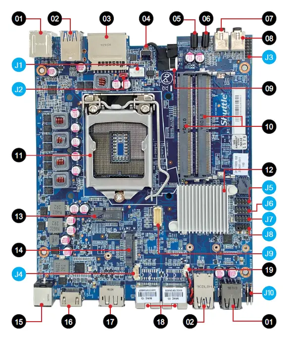
- SB 2.0 Port
- USB 3.2 Gen 1 Ports
- SD Card Reader (Option)
- Power Button
- Hard Disk Drive LED
- Power LED
- Headphones (Option)
- MIC-in (Option)
- SATA connector
- DDR4 SO-DIMM slots
- Processor socket LGA1200
- Intel® H410 Chipset
- M.2 2230 E key slot
- M.2 2242/2260/2280 M key slot
- Power Jack (DC IN)
- HDMI 2.0 Port
- Display Port
- LAN ports
- Battery connector
Jumper Settings
Fan connector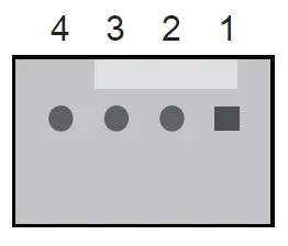
| CPU_FAN1 | |
| Pin | Signal Name |
| 1 | GND |
| 2 | +12V |
| 3 | SPEED_SENSE |
| 4 | PWM_CTRL |
AC auto power-on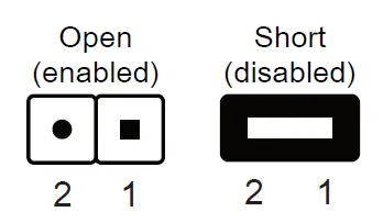
| JP2 | |
| Pin | Signal Name |
| 1 | AMP+ (From U30_pin5) |
| 2 | GND |
Audio connector (optional)
| AUDIO1 | |
| Pin | Signal Name |
| 1 | PULL AGND |
| 2 | LINE_R |
| 3 | NA |
| 4 | LINE_L |
| 5 | PULL AGND |
| 6 | FRONT_L |
| 7 | NULL |
| 8 | FRONT_SENSE |
| 9 | PULL AGND |
| 10 | FRONT_R |
| 11 | FR_AUDIO-JD |
| 12 | MIC1_R |
| 13 | AGND |
| 14 | MIC1_L |
USB connector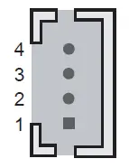
| CN12 | |
| Pin | Signal Name |
| 1 | GND |
| 2 | USB1P_C |
| 3 | USB1N_C |
| 4 | USBPW01 (+5V) |
Debug header
| Pin | Signal Name |
| 1 | LPC_24M |
| 2 | LAD1 |
| 3 | SIORST- |
| 4 | LAD0 |
| 5 | LFRAME- |
| 6 | +3.3V |
| 7 | LAD3 |
| 8 | GND |
| 9 | LAD2 |
| 10 | NULL |
COM port (R232/RS422/RS485)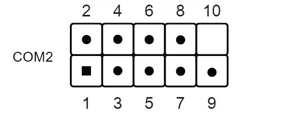
| Pin | Signal Name |
| 1 | DCD_485TX- |
| 2 | RX_485TX+ |
| 3 | TX_422RX+ |
| 4 | DTR_422RX- |
| 5 | GND |
| 6 | DSR |
| 7 | RTS |
| 8 | CTS |
| 9 | COM_-XRI1 |
| 10 | NULL |
COM port (RS232)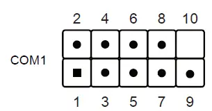
| Pin | Signal Name | Pin | Signal Name |
| 1 | DCD | 2 | RX |
| 3 | TX | 4 | DTR |
| 5 | GND | 6 | DSR |
| 7 | RTS | 8 | CTS |
| 9 | COM_-XRI2 | 10 | NULL |
COM 1 & COM 2 power switch \ COM 1 & COM 2
COM PORT Pin 9 “Ring Indicator” (RI) configuration:
Configure COM 1 with the first jumper:
- Short Pin 1-2: Pin 9 = RI1 (default)
- Short Pin 5-7: Pin 9 = +5V
- Short Pin 7-9: Pin 9 = +12V
Configure COM 2 with the second jumper:
- Short Pin 3-4: Pin 9 = RI2 (default)
- Short Pin 6-8: Pin 9 = +5V
- Short Pin 8-10: Pin 9 = +12V

Pin Signal Name Pin Signal Name 1 -XRI1 2 COM_-XRI1 3 -XRI2 4 COM_-XRI2 5 +5V 6 +5V 7 COM1_PWR 8 COM2_PWR 9 +12V 10 +12V

VGA connector (optional) 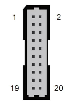
| CN6 | |||||
| Pin | Signal Name | Pin | Signal Name | Pin | Signal Name |
| 1 | GND | 2 | GND | 3 | VGASCL |
| 4 | GND | 5 | VGASDA | 6 | GND |
| 7 | GND | 8 | GND | 9 | CRT_VSYNC_R |
| 10 | GND | 11 | CRT_HSYNC_R | 12 | GND |
| 13 | GND | 14 | GND | 15 | BOUT-O |
| 16 | VGA_PWR | 17 | GOUT-O | 18 | VGA_PWR |
| 19 | ROUT-O | 20 | VGA_PWR | ||
Clear CMOS & power button & +5V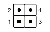
| SW1 | |
| Pin | Signal Name |
| 1 | RTCRST- |
| 2 | +5V |
| 3 | GND |
| 4 | PWRSW- |


