P22U Quick Guide
![]() 53R-P22U03-2001
53R-P22U03-2001
More information on this product can be found at: https://bit.ly/S-P22U
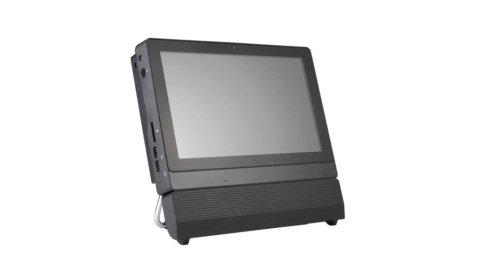
Product Overview
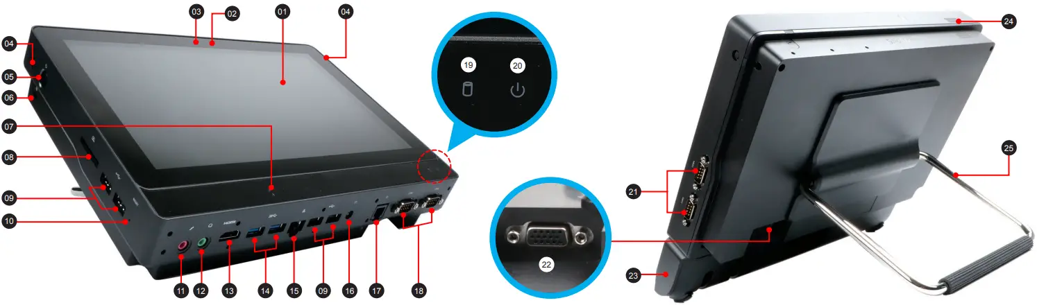
01. LCD display (Multi-touch)
02. Webcam status LED
03. Webcam
04. Two 4G external antennas (optional)
05. Power button
06. Kensington® Lock Hole
07. Microphone
08. SD card reader
09. USB 2.0 ports
10. Clear CMOS button
11. Microphone jack
12. Headphone / Line-out jack
13. HDMI port
14. USB 3.2 Gen 1 ports
15. LAN (RJ45) port
16. Power jack (DC-IN)
17. Cash drawer (RJ11) port (optional)
18. COM 1 and COM 2 ports
19. Hard disk drive LED
20. Power LED
21. COM 3 and COM 4 ports (optional)
22. D-Sub (VGA) port
23. Line collection box
24. Mono speaker
25. Stand / Handle
Hardware Installation
A. Begin Installation
![]() For safety reasons, please ensure that the power cord is disconnected before opening the case.
For safety reasons, please ensure that the power cord is disconnected before opening the case.
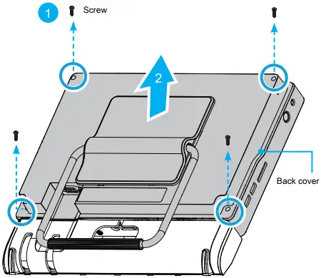
1. Unscrew four screws of the back cover.
2. Pull the back cover upward and remove it.
 3. Follow the steps a~c to remove the line collection box cover.
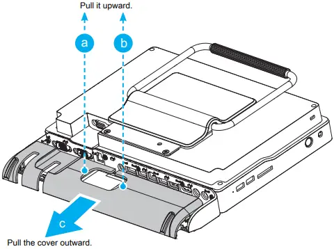
4. Place the cable/cord/wire inside the box and stow the extra cable lengths before closing the cover.
B. HDD or SSD Installation
1. Place an HDD or SSD in the rack and secure with the four screws from the sides. Affix the EMI shielding gasket with the adhesive tape, as shown.
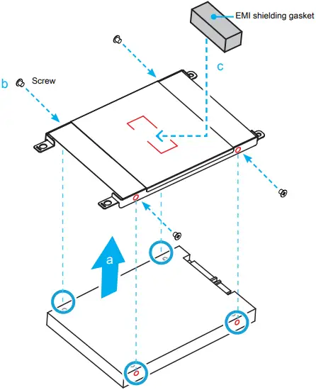
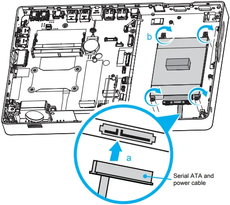
2. Tear off the adhesive tape of the serial ATA and power cable.
3. Connect the Serial ATA and power cable to the HDD or SSD. Slide the rack into the chassis and refasten the screws.
C. Memory Module Installation
![]() This motherboard does only support 1.2 V DDR4 SO-DIMM memory modules.
This motherboard does only support 1.2 V DDR4 SO-DIMM memory modules.
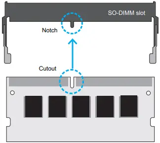
1. Locate the SO-DIMM slots on the motherboard.
2. Align the notch of the memory module with the one of the relevant memory slot.
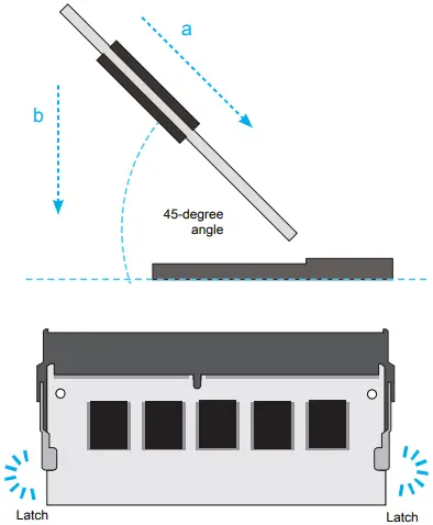
3. Gently insert the module into the slot in a 45-degree angle.
4. Carefully push down the memory module until it snaps into the locking mechanism and put back the mylar.
5. Repeat the above steps to install an additional memory module, if required.
D. M.2 Device Installation
1. Locate the M.2 key slots on the motherboard.
- M.2 2242/2260/2280 M key slot
 2. Install the M.2 device into the M.2 slot and secure with the screw.
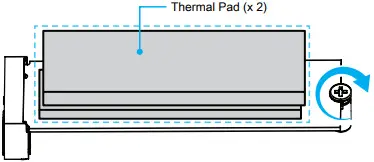
![]() Pasting the supplied thermal pad on the M.2 SSD can effectively reduce its temperature.
Pasting the supplied thermal pad on the M.2 SSD can effectively reduce its temperature.
E. Complete
1. Replace the back cover and refasten the screws.
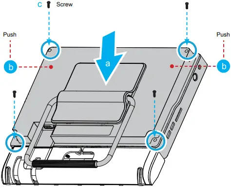
2. Complete
• Daughter board (CM008)
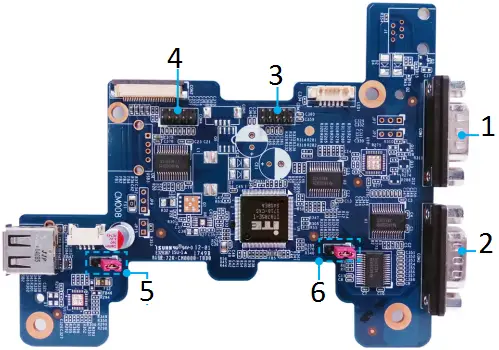
1. COM1
2. COM2
3. COM3 (optional)
4. COM4 (optional)
5. JP11: USB2 \ USB3 jumper for standby voltage![]() Pin1-2 = +5V (Default)
Pin1-2 = +5V (Default)
3 2 1![]() Pin2-3 = +5VS (Standby)
Pin2-3 = +5VS (Standby)
6. JP13: COM port quantity jumper![]() Pin1-2 = COM port x 2 (Default)
Pin1-2 = COM port x 2 (Default)
3 2 1![]() Pin2-3 = COM port x 3
Pin2-3 = COM port x 3![]() COM port x 4
COM port x 4
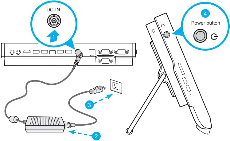
• Powering on the system
Follow the steps (1-3) below to connect the AC adapter to the power jack (DC-IN).
Press the (4) Power button to turn on the system.
![]() Please press the “Del” key while booting to enter BIOS. Here, please load the optimised BIOS settings.
Please press the “Del” key while booting to enter BIOS. Here, please load the optimised BIOS settings.
• VESA mounting it to the wall
If you are mounting your P22U to the wall, remove the cover from the back of the P22U first.
Unscrew four screws of the stand mount and remove the stand. The VESA standard makes it easy to mount the P22U on to walls. Please refer to the user guide of the wall/arm mount kit you bought separately how to install it.
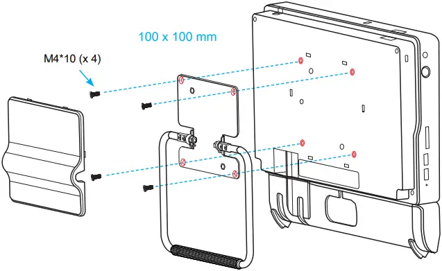
![]() The P22U can be mounted to a wall using a VESA compatible 100 x 100 mm wall/arm bracket.
The P22U can be mounted to a wall using a VESA compatible 100 x 100 mm wall/arm bracket.
• How to use the Touch Panel
The touch of your finger replaces the input devices and is all you need to operate the P22U.
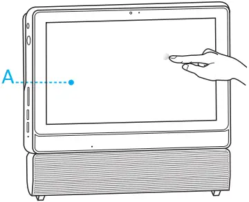
A ![]() Cleaning the screen
Cleaning the screen
Follow these guidelines for cleaning the outside and handling the screen of the computer:
Turn off the system and disconnect all cables. Use a cleaning cloth which is soft, lint-free and a little damp to gently wipe the screen surface.
Do not spray liquids directly onto the device.
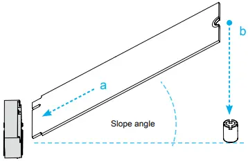
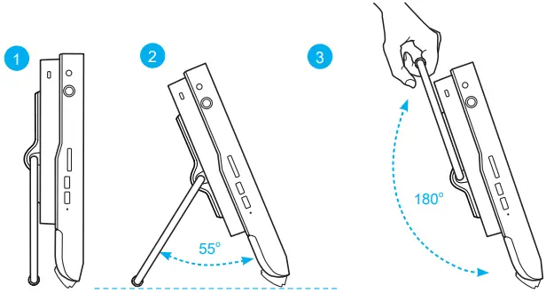
• Placing on a desk
To place the machine on a desk and to carry it, do the following:
1. Place the P22U on a flat surface such as a table.
2. Pull the stand upwards to an angle of 55°.
3. To carry or move your P22U, fully extend the angle to 180°.
Safety Information
![]() Incorrectly replacing the battery may damage this computer. Replace only with the same or equivalent as recommended by Shuttle. Dispose of used batteries according to the manufacturer’s instructions.
Incorrectly replacing the battery may damage this computer. Replace only with the same or equivalent as recommended by Shuttle. Dispose of used batteries according to the manufacturer’s instructions.
This device complies with Part 15 of the FCC Rules. Operation is subject to the following two conditions: (1) this device may not cause harmful interference, and (2) this device must accept any interference received, including interference that may cause undesired operation.
![]() This device meets the requirements for the EU conformity in accordance to the currently valid EU directives.
This device meets the requirements for the EU conformity in accordance to the currently valid EU directives.
* The equipment was evaluated for use in a maximum air ambient temperature of 40 ºC.
All bundled parts, power cord included, shall not be used without this product.


