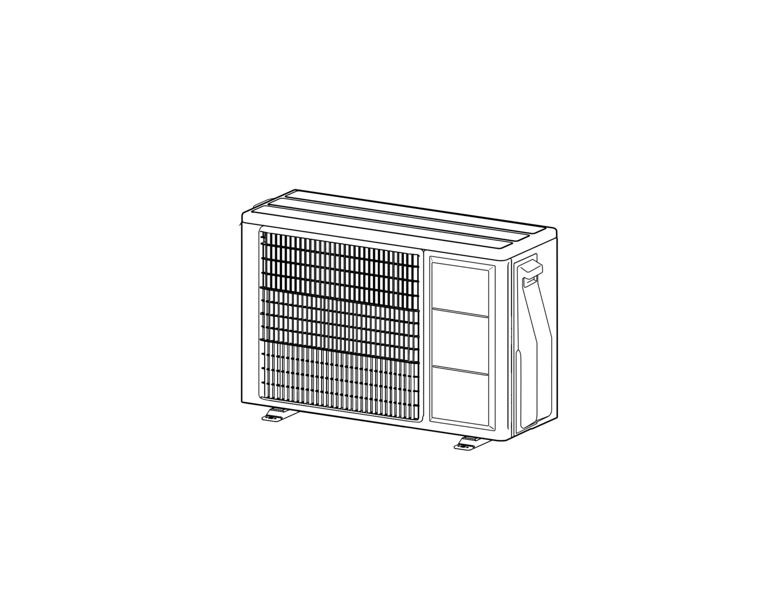
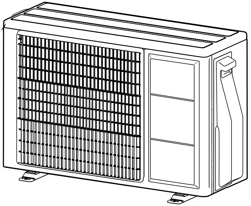
FUJITSU Air Conditioner Outdoor Unit
Installation must be performed in accordance with the requirement of NEC and CEC by authorized personnel only
SAFETY PRECAUTIONS
IMPORTANT! Please read before starting
This air conditioning system meets strict safety and operating standards.
As the installer or service person, it is an important part of your job to install or service the system so it operates safely and efficiently.
For safe installation and trouble-free operation, you must:
- Carefully read this instruction booklet before beginning.
- Follow each installation or repair step exactly as shown.
- Observe all local, state, and national electrical codes.
- Pay close attention to all warning and caution notices given in this manual.
 This symbol refers to a hazard or unsafe practice which can result in severe personal injury or death.
 This symbol refers to a hazard or unsafe practice which can result in personal injury and the potential for product or property damage.
 - Hazard alerting symbols
 Electrical
 Safety/alert
If Necessary, Get Help
These instructions are all you need for most installation sites and maintenance conditions.
If you require help for a special problem, contact our sales/service outlet or your certified dealer for additional instructions.
In Case of Improper Installation
The manufacturer shall in no way be responsible for improper installation or maintenance service, including failure to follow the instructions in this document.
Special precautions
When Wiring
ELECTRICAL SHOCK CAN CAUSE SEVERE PERSONAL INJURY OR DEATH. ONLY A QUALIFIED, EXPERIENCED ELECTRICIAN SHOULD ATTEMPT TO WIRE THIS SYSTEM.
- Do not supply power to the unit until all wiring and tubing are completed or reconnected and checked.
- Highly dangerous electrical voltages are used in this system. Carefully refer to the wiring diagram and these instructions when wiring. Improper connections and inadequate grounding (earthing) can cause accidental injury or death.
- Ground (Earth) the unit following local electrical codes.
- Connect all wiring tightly. Loose wiring may cause overheating at connection points and a possible fire hazard.
When Transporting
Be careful when picking up and moving the indoor and outdoor units. Get a partner to help, and bend your knees when lifting to reduce strain on your back. Sharp edges or thinaluminum fins on the air conditioner can cut your fingers.
When Installing…
…In a Ceiling or Wall
Make sure the ceiling/wall is strong enough to hold the unit’s weight. It may be necessary to construct a strong wood or metal frame to provide added support.
…In a Room
Properly insulate any tubing run inside a room to prevent “sweating” that can cause dripping and water damage to walls and floors.
…In Moist or Uneven Locations
Use a raised concrete pad or concrete blocks to provide a solid, level foundation for the outdoor unit. This prevents water damage and abnormal vibration.
…In an Area with High Winds
Securely anchor the outdoor unit down with bolts and a metal frame. Provide a suitable air baffle.
…In a Snowy Area (for Heat Pump-type Systems)
Install the outdoor unit on a raised platform that is higher than drifting snow.
When Connecting Refrigerant Tubing
- Keep all tubing runs as short as possible.
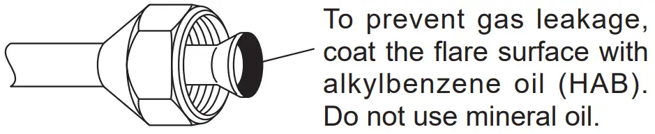
- Use the flare method for connecting tubing.
- Apply refrigerant lubricant to the matching surfaces of the flare and union tubes before connecting them, then tighten the nut with a torque wrench for a leak-free connection.
- Check carefully for leaks before opening the refrigerant valves.
NOTE:
Depending on the system type, liquid and gas lines may be either narrow or wide. Therefore, to avoid confusion the refrigerant tubing for your particularmodel is specified as either “small” or “large” rather than as “liquid” or “gas”.
When Servicing
- Turn the power OFF at the main circuit breaker panel before opening the unit to check or repair electrical parts and wiring.
- Keep your fingers and clothing away from any moving parts.
- Clean up the site after you finish, remembering to check that no metal scraps or bits of wiring have been left inside the unit being serviced
- After installation, explain correct operation to the customer, using the operating manual.
|
|
|
PRODUCT SPECIFICATION
- All Fujitsu General products are manufactured to metric units and tolerances.
United States customary units are provided for reference only. In cases where exact dimensions and tolerances are required, always refer to metric units.
Installation tools
|
| To install a unit that uses R410A refrigerant, use dedicated tools and piping materials that have been manufactured specifically for R410A use. Because thepressure of R410A refrigerant is approximately 1.6 times higher than R22, failure to use dedicated piping material or improper installation can cause rupture or injury. Furthermore, it can cause serious accidents such as water leakage, electric shock, or fire. |
| Tool name | Change from R22 to R410A |
| Gauge manifold | Pressure is high and cannot be measured with a conven- tional (R22) gauge. To prevent erroneous mixing of other refrigerants, the diameter of each port has been changed. It is recommended to use gauge with seals -0.1 to 5.3 MPa (-1 to 53 bar) for high pressure. -0.1 to 3.8 MPa (-1 to 38 bar) for low pressure. |
| Charge hose | To increase pressure resistance, the hose material and base size were changed.(R410A) |
| Vacuum pump | A conventional vacuum pump can be used by installing a vacuum pump adapter. (Use of a vacuum pump with a series motor is prohibited.) |
| Gas leakage detector | Special gas leakage detector for HFC refrigerant R410A. |
Copper pipes
It is necessary to use seamless copper pipes and it is desirable that the amount of residual oil is less than 0.0014 oz/33 ft (40 mg/10 m). Do not use copper pipeshaving a collapsed, deformed or discolored portion (especially on the interior surface). Otherwise, the expansion value or capillary tube may become blocked with contaminants.
As an air conditioner using R410A incurs pressure higher than when using R22, it is necessary to choose adequate materials.
Thicknesses of copper pipes used with R410A are as shown in table.
Never use copper pipes thinner than those indicated in the table even if they are available on the market.
Thicknesses of Annealed Copper Pipes
| Nominal diameter (in) | Outer diameter (mm) | Thickness [in(mm)] |
| 1/4 | 6.35 | 0.031 (0.80) |
| 3/8 | 9.52 | |
| 1/2 | 12.70 | |
| 5/8 | 15.88 | 0.039 (1.00) |
| 3/4 | 19.05 | 0.047 (1.20) |
Accessories
|
| For installation purposes, be sure to use the parts supplied by the manufacturer or other prescribed parts. The use of non-prescribed parts can cause serious accidents such as the unit falling, water leakage, electric shock, or fire. |
- The following installation parts are supplied. Use them as required.
- Keep the Installation Manual in a safe place and do not discard any other accessories until the installation work has been completed.
| Name and Shape | Q’ty | Name and Shape | Q’ty |
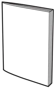
Installation manual (This manual) | 1 | Drain pipe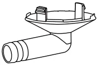 | 1 |
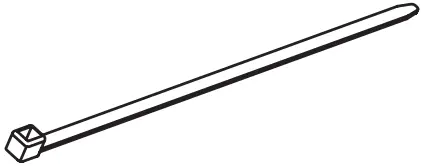
Drain cap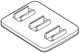 | 5 | Cable tie | 2 |
One set of following parts are necessary installation of this product.
Additional materials | |||
| Connection pipe assembly | Decorative tape | Saddle | Tapping screws |
| Connection cable | Vinyl tape | Drain hose | Sealant |
| Wall pipe | Wall cap | M10 bold, nut | |
Pipe requirement
Protection of pipes
- Protect the pipes to prevent the entry of moisture and dust.
- Especially, pay attention when passing the pipes through a hole or connecting the end of a pipe to the outdoor unit
| Location | Working period | Protection method |
| Outdoor | 1 month or more | Pinch pipes |
| Less than 1 month | Pinch or tape pipes | |
| Indoor | – | Pinch or tape pipes |
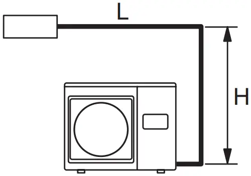
Refrigerant pipe size and allowable piping length
|
|
Model | 9, 12 | 18 |
Pipe diameter <Liquid/Gas> [in (mm)] | 1/4 (6.35) / 3/8 (9.52) | 1/4 (6.35) / 1/2 (12.70) |
| Max. piping length (L) [ft (m)] | 66 (20) | 98 (30) |
Max. height difference (H) <Indoor unit to outdoor unit> [ft (m)] | 49 (15) | |
| View (Example) |
| |
Power source
|
|
|
|
Electric requirement
|
|
| Voltage rating | 1 ø 208/230 V (60 Hz) |
| Operating range | 187-253 V |
| Cable | Type | Remarks |
| Power supply cable | 14 AWG | 2 cable + Ground (Earth), 1 ø 208/230 V |
| Connection cable | Refer to the installation manual of the indoor unit for the connection cable specifications. | |
Select the correct cable type and size according to the country or region’s regulations. Max. wire length: Set a length so that the voltage drop is less than 2%. Increase the wire diameter when the wire length is long
| ||
Outdoor unit capacity | MINIMUM CIRCUIT AMPACITY | MAX. CKT. BKR. |
| 9 | 11.5 A | 15 A |
12 | 13.8 A | 15 A |
| 18 | 18.1 A | 20 A |
- Before starting work check that power is not being supplied to all poles of the indoor unit and outdoor unit.
- Install all electrical works in accordance to the national standard.
- Install the disconnect device with a contact gap of at least 1/8 in (3 mm) in all poles nearby the units. (Both indoor unit and outdoor unit)
- nstall the circuit breaker nearby the units.
Additional charge
|
| When adding refrigerant, add the refrigerant from the charging port at the completion of work. |
Refrigerant suitable for a piping length of 49 ft (15 m) [09, 12 model] or 66 ft (20 m) [18 model] is charged in the outdoor unit at the factory.
When the piping is longer than 49 ft (15 m) [09, 12 model] or 66 ft (20 m) [18 model], additional charging is necessary.
Enter the total refrigerant amount to the label affixed to the outdoor unit.
For the additional amount, refer to the following table.
Pipe length | Model | 49 ft (15 m) | 66 ft (20 m) | 82 ft (25 m) | 98 ft (30 m) | Rate |
Additional refrigerant | 9, 12 | None | + 4 oz (+ 100 g) | – | – | 0.2 oz/ft (20 g/m) |
| 18 | None | None | + 4 oz (+ 100 g) | + 7 oz (+ 200 g) | 0.2 oz/ft (20 g/m) |
Between 49 ft (15 m) [09, 12 model] or 66 ft (20 m) [18 model] and the maximum length, when using a connection pipe other than that in the table, charge additional refrigerant with 0.2 oz/ft (20 g/m) as the criteria.
* Refer to “Refrigerant pipe size and allowable piping length”
Model | Maximum amount of refrigerant charge |
9 | 2 lbs 7 oz (2 lbs 3 oz + 4 oz) [1100 g (1000 g + 100 g)] |
| 12 | 2 lbs 14 oz (2 lbs 10 oz + 4 oz) [1300 g (1200 g + 100 g)] |
18 | 3 lbs 3 oz (2 lbs 12 oz + 4 oz) [1450 g (1250 g + 200 g)] |
Operating range
Cooling mode Dry mode | Heating mode [Reverse cycle model only] | |
| Outdoor temperature | 14 to 115 °F (-10 to 46 °C) | -5 to 75 °F (-21 to 24 °C) |
- If this unit is operated outside the operating temperature, the protection circuits may be activated to stop the unit.
INSTALLATION WORK
Make sure to obtain the customer’s approval for selecting and installing the outdoor unit.
Selecting an installation location
|
|
|
|
Decide the mounting position with the customer as follows:
- Install the outdoor unit in a location which can withstand the weight of the unit and vibration, and which can install horizontally.
- Provide the indicated space to ensure good airflow.
- If possible, do not install the unit where it will be exposed to direct sunlight.
(If necessary, install a blind that does not interfere with the airflow.) - Do not install the unit near a source of heat, steam, or flammable gas.
- During heating operation, drain water flows from the outdoor unit.
Therefore, install the outdoor unit in a place where the drain water flow will not be obstructed. - Do not install the unit where strong wind blows or where it is very dusty.
- Do not install the unit where people pass.
- Install the outdoor unit in a place where it will be free from being dirty or getting wet by rain as much as possible.
- Install the unit where connection to the indoor unit is easy
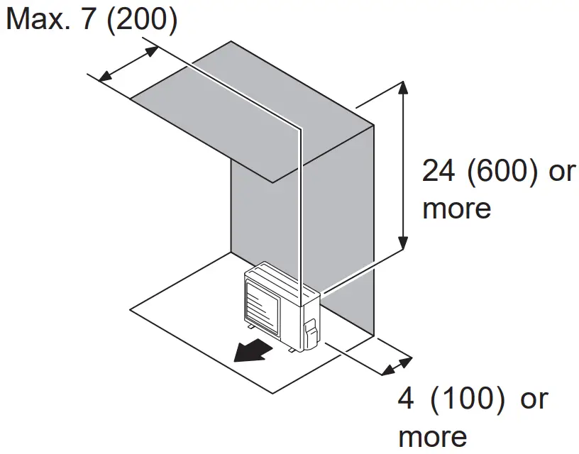
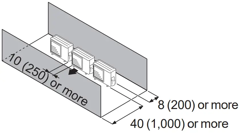
Installation dimensions
|
| Keep the space shown in the installation examples. If the installation is not performed accordingly, it could cause a short circuit and result in a lack of operating performance. |
Outdoor unit installation
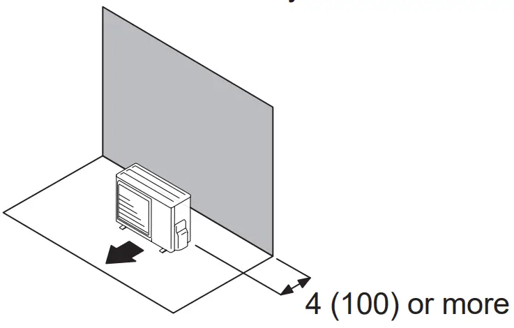
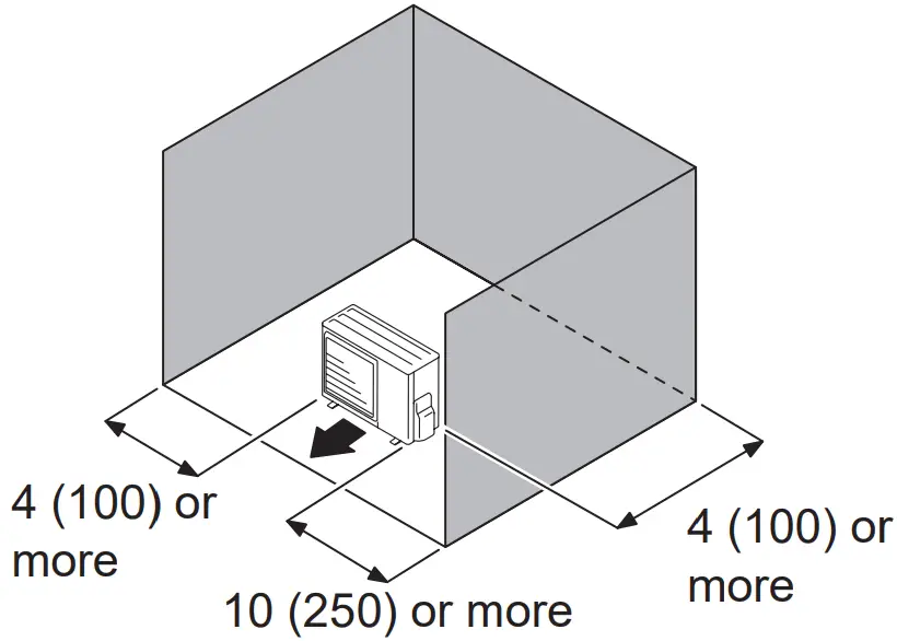
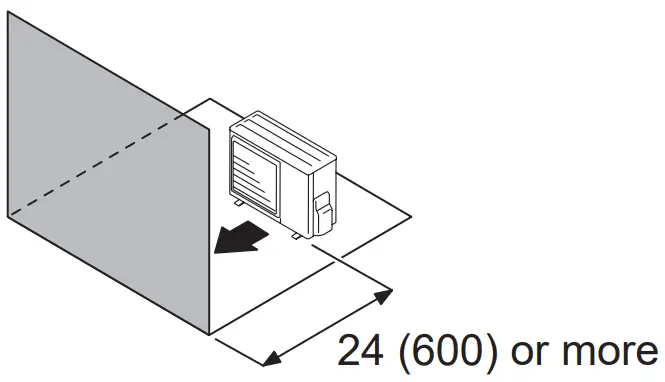
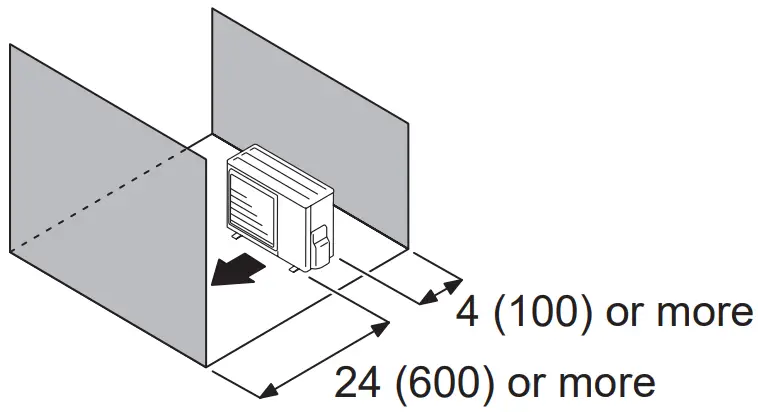
When the upper space is open [ Unit: in (mm) ]
- Obstacles at rear only

- Obstacles at rear and sides

- Obstacles at front

- Obstacles at front and rear

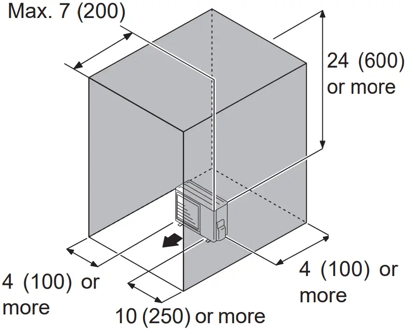
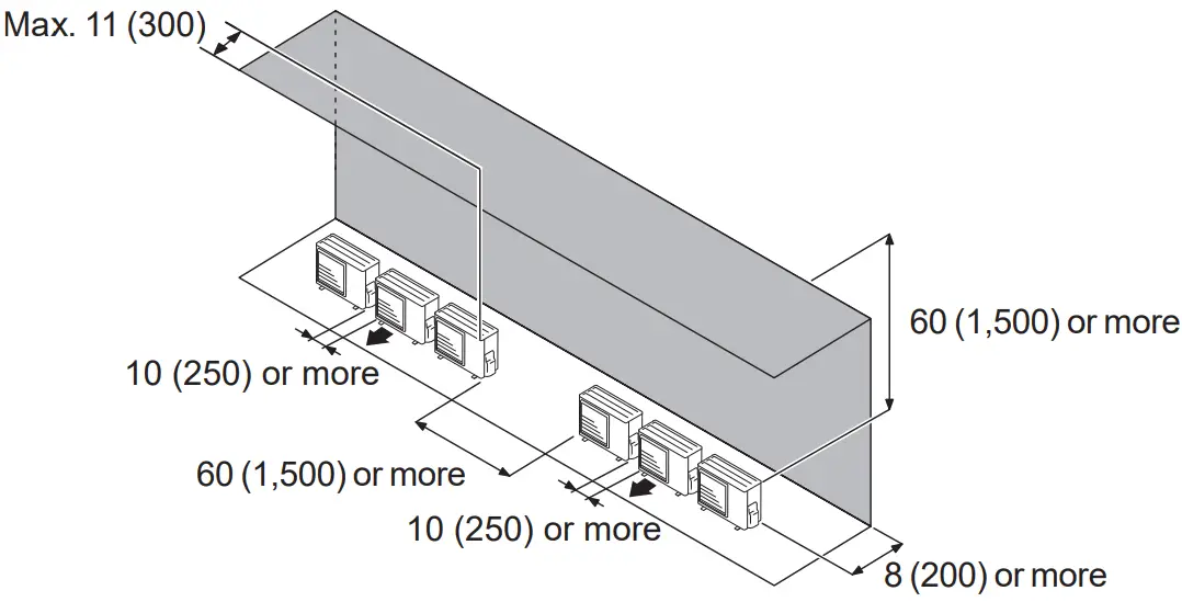
When an obstruction in the upper space [ Unit: in (mm) ]
- Obstacles at rear and above

- Obstacles at rear, sides, and above

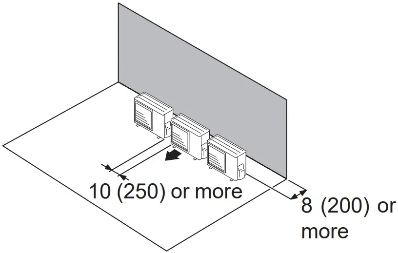
Multiple outdoor unit installation
- Provide at least 10 in (250 mm) of space between the outdoor units if multiple units are installed.
- When routing the piping from the side of an outdoor unit, provide space for the piping.
- Up to 3 units can be installed side by side
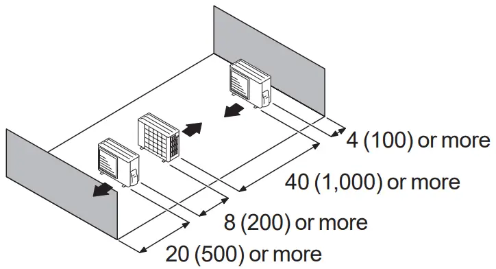
When the upper space is open [ Unit: in (mm) ]
- Obstacles at rear only

- Obstacles at front only

- Obstacles at front and rear

When an obstruction in the upper space [ Unit: in (mm) ]
Obstacles at rear and above
- Up to 3 units can be installed side by side.
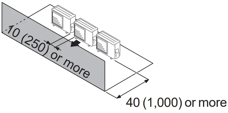
- When 4 units or more are arranged in a line, provide the space as shown below.

Outdoor units installation multi-row [ Unit: in (mm) ]
- Single parallel unit arrangement

- Multiple parallel unit arrangement

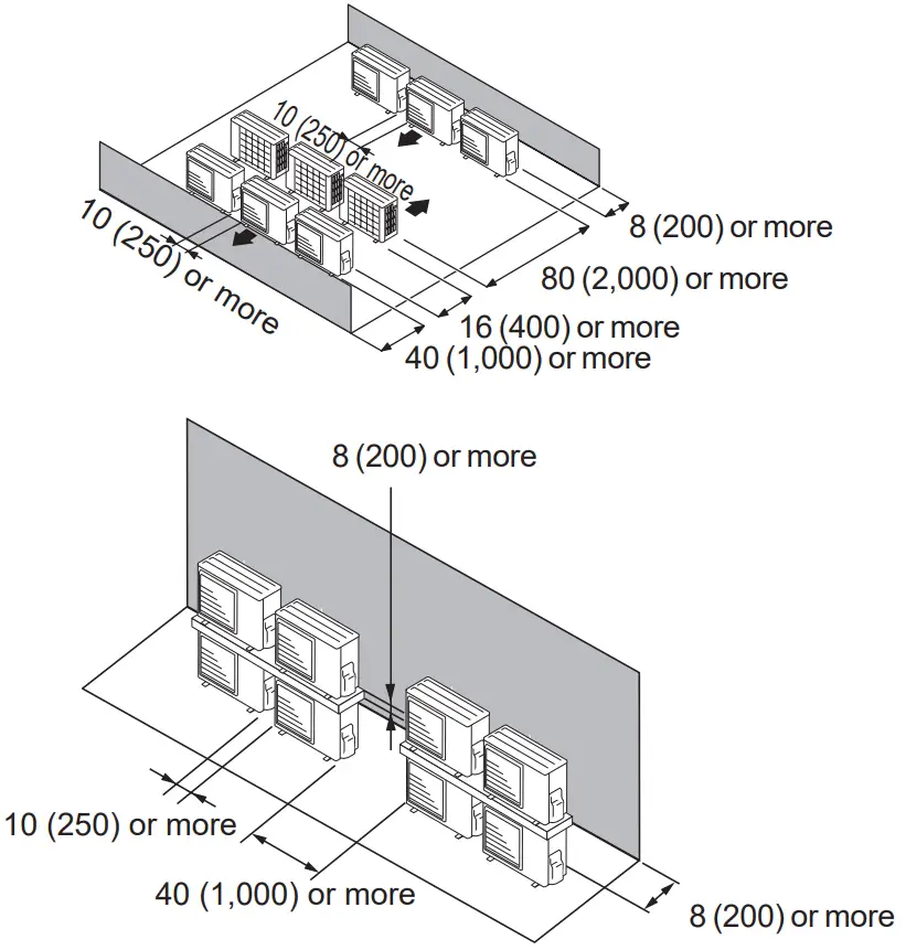
|
| Do not install the outdoor unit in two-stage where the drain water could freeze. Otherwise the drainage from the upper unit may form ice and cause a malfunction of the lower unit. |
NOTES:
- If the space is larger than stated above, the condition will be the same as when there is no obstacle.
- When installing the outdoor unit, be sure to open the front and left side to obtain better operation efficiency.
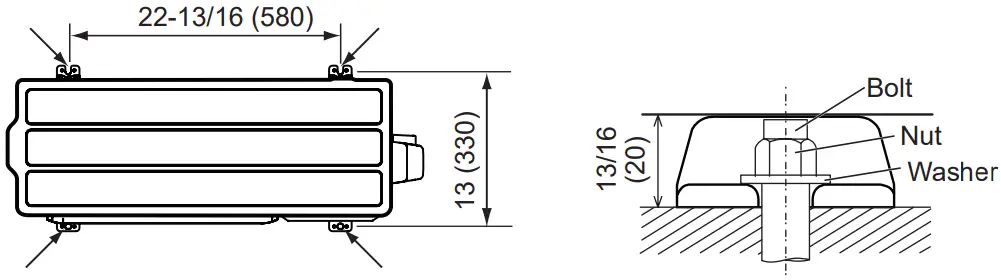
Mounting the unit
- Install 4 anchor bolts at the locations indicated with arrows in the figure.
- To reduce vibration, do not install the unit directly on the ground. Install it on a secure base (such as concrete blocks).
- Depending on the installation conditions, the outdoor unit may spread its vibration during operation, which may cause noise and vibration. Therefore, attach damping materials (such as damping pads) to the outdoor unit during installation.
- Install the foundation, making sure that there is enough space for installing the connection pipes.
- Secure the unit to a solid block using foundation bolts. (Use 4 sets of commercially available M10 bolts, nuts, and washers.)
- The bolts should protrude 1 in (20 mm). (Refer to the figure.)
- If overturning prevention is required, purchase the necessary commercially available items.
- The foundation shall support the legs of the unit and have a width of 2 in (50 mm) or more.


|
To ensure stable operation, the outdoor unit must be installed on a raised stand or rack, at or above the anticipated snow depth for the region. |
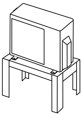
[ Unit: in (mm) ]
Drain installation
|
| When the outdoor temperature is 32°F (0°C) or less, do not use the accessory drain pipe and drain cap. If the drain pipe and drain cap are used, the drain water in the pipe may freeze in extreme cold weather. (Reverse cycle model only) |
- Since the drain water flows out of the outdoor unit during heating operation,install the drain pipe and connect it to a commercial 5/8 in (16 mm) hose.
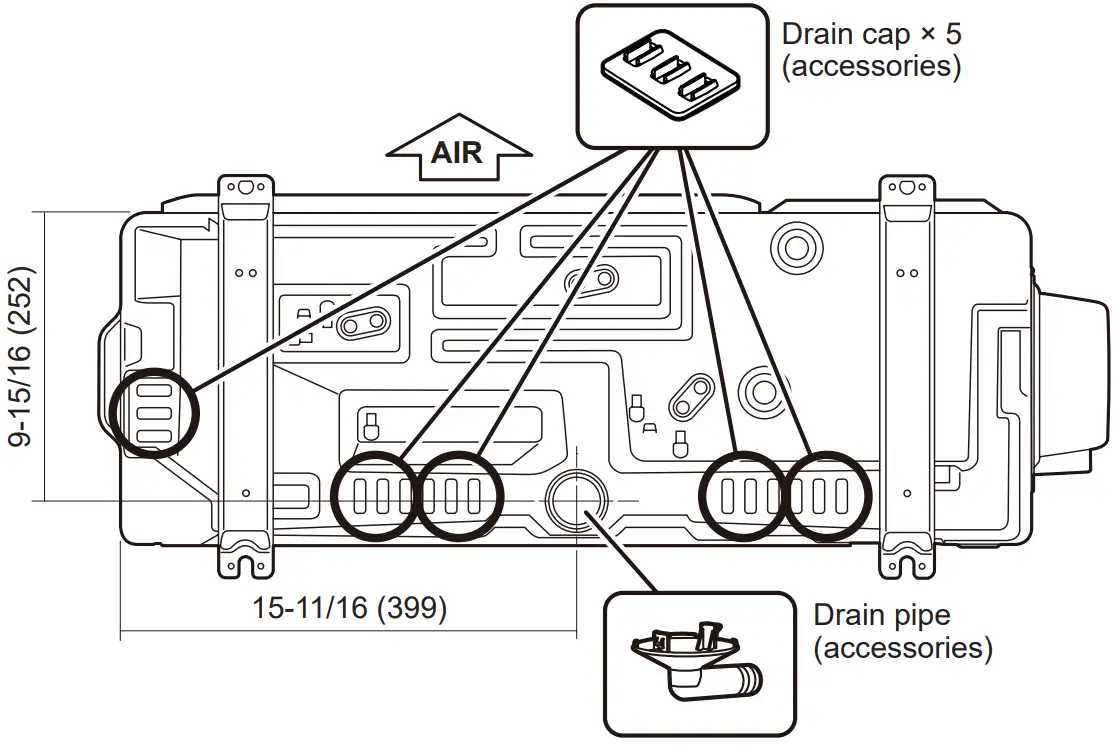
- When installing the drain pipe, plug all the holes other than the drain pipe mounting hole in the bottom of the outdoor unit with putty so there is nowater leakage.

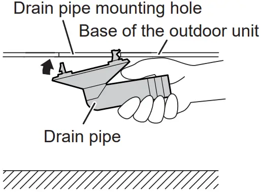
[ Unit: in (mm) ]
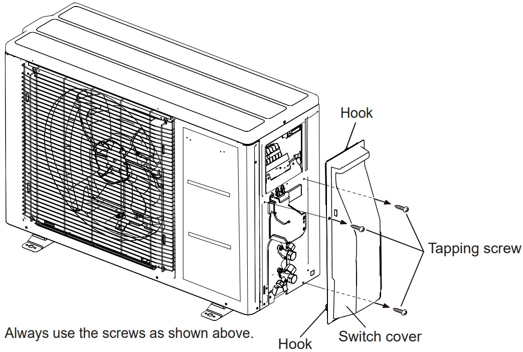
Removing and replacing parts
Switch cover removal
- Remove the tapping screws.
- Slide the switch cover downwards to release.
Installing the switch cover
- After inserting the hooks (2 places) on the switch cover into the hole on the outdoor unit, slide the switch cover upwards.
- Replace the tapping screws
Pipe installation
|
|
- Flaring
- Cut the connection pipe to the necessary length with a pipe cutter.
- Hold the pipe downward so that cuttings will not enter the pipe and remove the burrs.
- Insert the flare nut onto the pipe and flare the pipe with a flaring tool. Insert the flare nut (always use the flare nut attached to the indoor and outdoor units respectively) onto the pipe and perform the flare processing with a flare tool.
Use the special R410A flare tool, or the conventional (for R22) flare tool.
When using the conventional flare tool, always use an allowance adjustment gauge and secure the A dimension shown in the following table.
Check if [L] is flared uniformly and is not cracked or scratched.
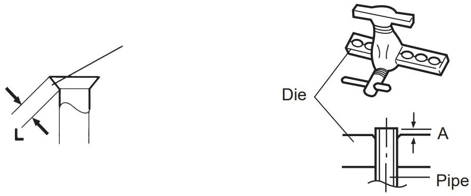
| Pipe outside diameter [in (mm)] | Dimension A [in (mm)] |
| Flare tool for R410A, clutch type | |
| 1/4 (6.35) | 0 to 0.020 |
| 3/8 (9.52) | |
| 1/2 (12.70) | |
| 5/8 (15.88) | |
| 3/4 (19.05) |
- Bending pipes
(1) When bending the pipe, be careful not to crush it.
(2) To prevent breaking of the pipe, avoid sharp bends.
Bend the pipe with a radius of curvature of 2-3/8 in (70 mm) or more.
(3) If the copper pipe is bend the pipe or pulled too often, it will become stiff. Do not bend the pipes more than three times at one place.
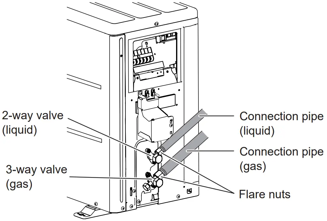
- Flare connection
- Detach the caps and plugs from the pipes
 CAUTION
- Be sure to apply the pipe against the port on the indoor unit and the outdoor unit correctly. If the centering is improper, the flare nut cannot be tightened smoothly. If the flare nut is forced to turn, the threads will be damaged.
- Do not remove the flare nut from the indoor unit pipe until immediately before connecting the connection pipe.
- Centering the pipe against port on the outdoor unit, turn the flare nut with your hand.

- Tighten the flare nut of the connection pipe at the outdoor unit valve connector.

- When the flare nut is tightened properly by your hand, use a torque wrench to finally tighten it

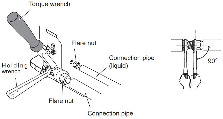
|
| Hold the torque wrench at its grip, keeping it in the right angle with the pipe, in order to tighten the flare nut correctly. |
| Flare nut [in (mm)] | Tightening torque [lbf·ft. (N·m)] |
| 1/4 (6.35) dia. | 11.8 to 13.3 (16 to 18) |
| 3/8 (9.52) dia. | 23.6 to 31.0 (32 to 42) |
| 1/2 (12.70) dia. | 36.1 to 45.0 (49 to 61) |
| 5/8 (15.88) dia. | 46.5 to 55.3 (63 to 75) |
| 3/4 (19.05) dia. | 66.4 to 81.1 (90 to 110) |
|
|
Sealing test
|
|
|
|
- After connecting the pipes, perform a sealing test.
- Make sure that the 3-way valves are closed before performing a sealing test.
- Pressurize nitrogen gas to 4.15 MPa to perform the sealing test.
- Add nitrogen gas to both the liquid pipes and the gas pipes.
- Check all flare connections and welds. Then, check that the pressure has not decreased.
- Compare the pressures after pressurizing and letting it stand for 24 hours, and check that the pressure has not decreased.
* When the outdoor air temperature changes 41 °F (5 °C), the test pressure changes 0.05 MPa. If the pressure has dropped, the pipe joints may be leaking. - If a leak is found, immediately repair it and perform the sealing test again.
- After completing the sealing test, release the nitrogen gas from both valves.
- Release the nitrogen gas slowly.
Vacuum process
|
|
Refrigerant for purging the air is not charged in the outdoor unit at the factory.
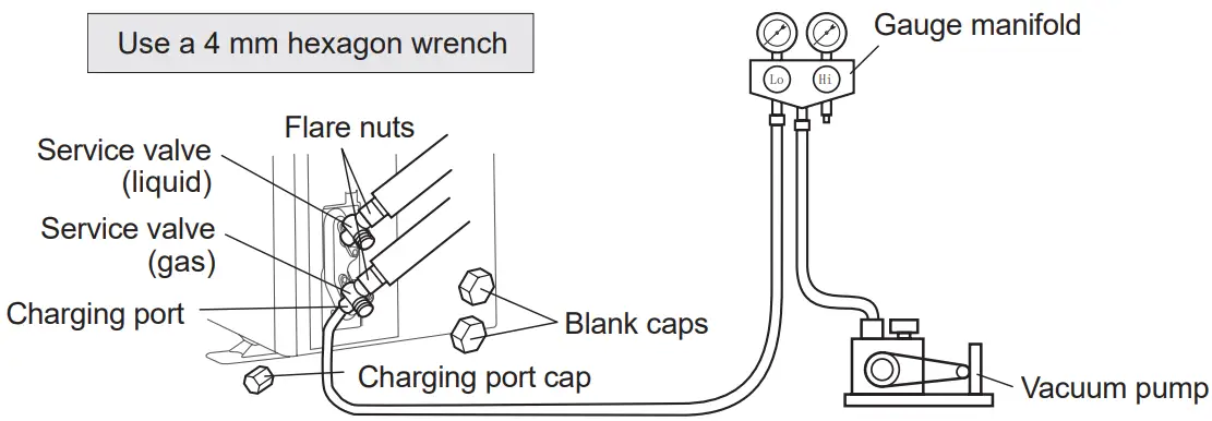
- Remove the cap, and connect the gauge manifold and the vacuum pump to the charging valve by the service hoses.
- Vacuum the indoor unit and the connecting pipes until the pressure gauge indicates –0.1 MPa (–76 cmHg).
- When –0.1 MPa (–76 cmHg) is reached, operate the vacuum pump for at least60 minutes.
- Disconnect the service hoses and fit the cap to the charging valve to the specified torque.
- Remove the blank caps, and fully open the spindles of the 3-way valves with a hexagon wrench [Torque: 4 to 5 lbs·ft (6~7 N·m)].
- Tighten the blank caps of the 3-way valves to the specified torque
| Tightening torque [lbs·ft (N·m)] | ||
| Blank cap [in (mm)] | 1/4 (6.35) | 14.8 to 18.4 (20 to 25) |
| 3/8 (9.52) | 14.8 to 18.4 (20 to 25) | |
| 1/2 (12.70) | 18.4 to 22.1 (25 to 30) | |
| 5/8 (15.88) | 22.1 to 25.8 (30 to 35) | |
| 3/4 (19.05) | 25.8 to 29.5 (35 to 40) | |
| Charging port cap | 7 to 9 (10 to 12) | |
Additional charging
|
| When moving and installing the air conditioner, do not mix gas other than the specified refrigerant R410A inside the refrigerant cycle. If air or other gas enters the refrigerant cycle, the pressure inside the cycle will rise to an abnormally high value and cause breakage, injury, etc |
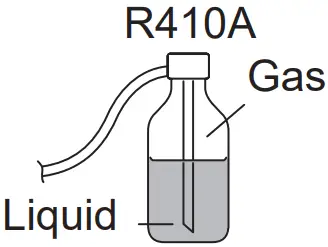
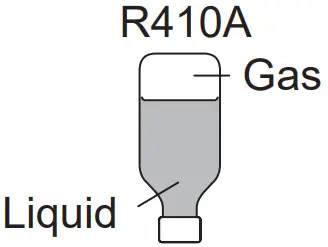
|
Filling method for cylinder with siphon Set the cylinder vertical and fill with the liquid. Filling method for other cylinders Turn bottom up and fill with liquid.
|
- Gas leakage inspection
|
| After connecting the piping, check the all joints for gas leakage with gas leak detector. |
Electrical wiring
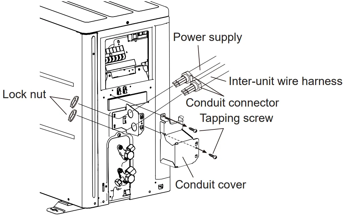
Conduit installation
- Remove the tapping screw, then remove the conduit cover.
- Fasten the Inter-unit wire harness and power supply to the conduit holder using the lock nut.
- Connect inter-unit wire harness and power supply to the terminal.
- Use the tapping screw to install the conduit cover.
NOTES:
- Connector trade size for this unit is 1/2 inch. The connector can be bought at a hard ware store. Refer to “3.10.2. Notes for electrical wiring ■ How to connect wiring to the terminal”.
- The fuse located in the outdoor unit provides power supply protection and may blow when power is applied if the system has been incorrectly wired.

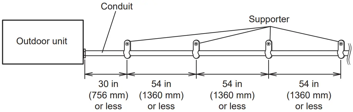
Fix the conduit with the supporters as shown below.
Notes for electrical wiring
|
|
|
|
- How to connect wiring to the terminal
Caution when wiring cable
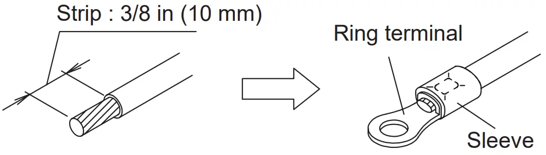
- When stripping off the coating of a lead wire, always use a special tool such as a wire stripper. If there is no special tool available, carefully strip the coating with a knife etc.
- Use ring terminals with insulating sleeves as shown in the figure below to connect to the terminal block.
- Securely clamp the ring terminals to the wires using an appropriate tool so that the wires do not come loose.

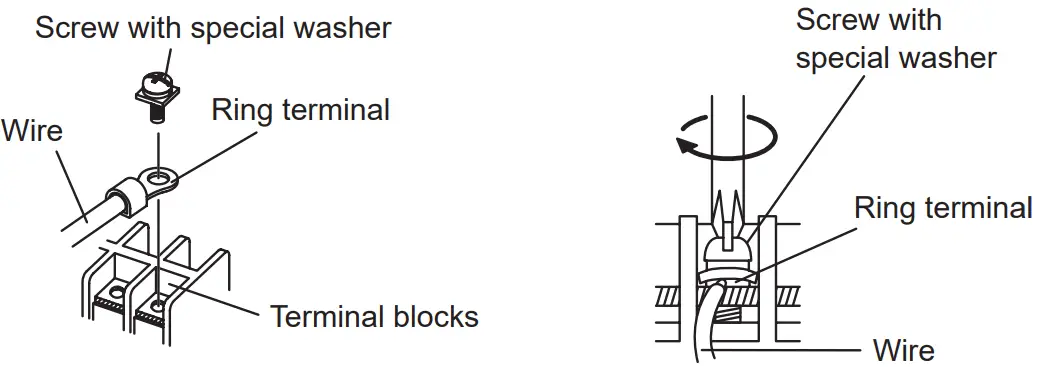
- Use the specified wires, connect them securely, and fasten them so that there is no stress placed on the terminals.
- Use an appropriate screwdriver to tighten the terminal screws. Do not use a screwdriver that is too small, otherwise, the screw heads may be damaged and prevent the screws from being properly tightened.
- Do not tighten the terminal screws too much, otherwise, the screws may break.

- Refer to the following table for the terminal screw tightening torques.
Tightening torque [lbs·in (N·m)] | |
| M3.5 screw | 7.0 to 8.8 (0.8 to 1.0) |
M4 screw | 10.6 to 15.9 (1.2 to 1.8) |
| M5 screw | 17.7 to 26.5 (2.0 to 3.0) |
Wiring method
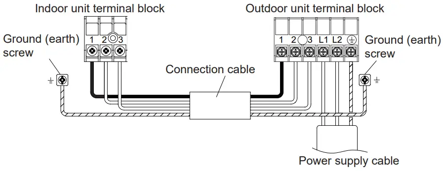
- Connection diagrams
|
| When connecting the power supply cable, make sure that the phase of the power supply matches with the phase of the terminal board. If the phases do not match, the compressor will rotate in reverse and will not be able to compress. |
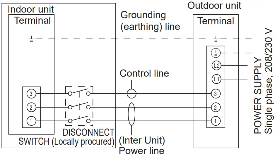
NOTE: Factory installed protective inline fuses for indoor units’ conductors are installed on the Power Supply PCB.
- Cable preparation
Keep the ground (earth) wire longer than the other wires.
NOTE: When using a sealed cable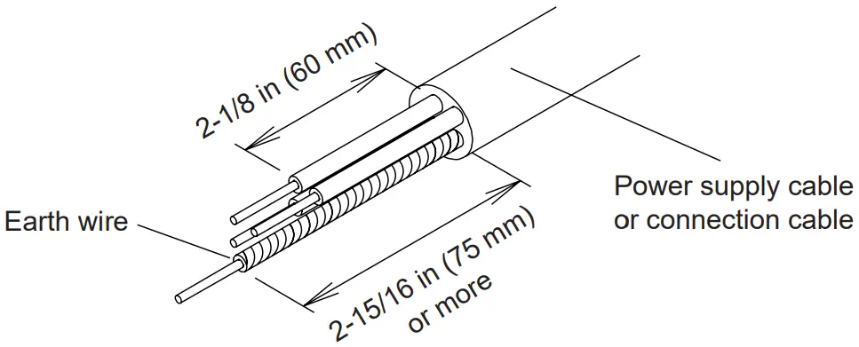
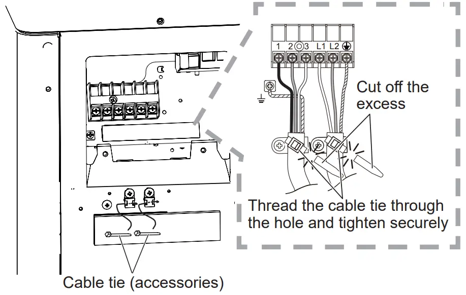
- Wiring procedure
- Remove the outdoor unit switch cover.(Refer to “3.5.1. Switch cover removal”.)
- Remove the outdoor unit conduit cover. (Refer to “3.10.1. Conduit installation”.)
- Connect the power supply cable and the connection cable to terminal.
- Fasten the power supply cable and connection cable with cable tie (accessories).
- Install the conduit cover.(Refer to “3.10.1. Conduit installation”.)

TEST RUN
Make a test run in accordance with the installation manual for the indoor unit.
FINISHING
Installing insulation
- Install insulation material after conducting “3.7. Sealing test”.
- To prevent condensation and water droplets, install insulation material on the refrigerant pipe.
- Use insulation with heat resistance above 248 °F (120 °C).
- Refer to the table to determine the thickness of the insulation material.
■ Selection of insulation
(Use an insulation material with equal heat transmission rate or below 0.040 W/(m·k))
| Insulation material minimum thickness [in (mm)] | |||||
| Relative humidity | ≤ 70% | ≤ 75% | ≤ 80% | ≤ 85% | |
| Pipe diameter [in (mm)] | 1/4 (6.35) | 5/16 (8) | 3/8 (10) | 1/2 (13) | 11/16 (17) |
| 3/8 (9.52) | 3/8 (9) | 7/16 (11) | 9/16 (14) | 11/16 (18) | |
| 1/2 (12.70) | 3/8 (10) | 1/2 (12) | 9/16 (15) | 3/4 (19) | |
| 5/8 (15.88) | 3/8 (10) | 1/2 (12) | 5/8 (16) | 13/16 (20) | |
| 3/4 (19.05) | 3/8 (10) | 1/2 (13) | 5/8 (16) | 13/16 (21) | |
* When the ambient temperature and relative humidity exceed 89.6 °F (32 °C) (DB) and 85% respectively, please strengthen the heat insulation of refrigerant pipe.
PUMP DOWN
- Pump down operation (forced cooling operation)
To avoid discharging refrigerant into the atmosphere at the time of relocation or disposal, recover refrigerant by doing the forced cooling operation according to the following procedure.
- Conduct preliminary operation for 5 to 10 minutes using the forced cooling operation. Start the forced cooling operation. Keep on pressing the [MANUAL AUTO] of the indoor unit for more than 10 seconds. The operation indicator lamp and timer indicator lamp will begin to flash simultaneously during test run. (The forced cooling operation cannot start if the [MANUAL AUTO] is not kept on pressing for more than 10 seconds.)
- Close the valve stem of 2-way valve completely.
- Continue the forced cooling operation for 2 to 3 minutes, then close all the valve stems on the 3-way valves
- Stop the operation.
- Press the [START/STOP] of the remote controller to stop the operation.
- Press the [MANUAL AUTO] when stopping the operation from the indoor unit side.
(It is not necessary to press down for more than 10 seconds.)
|
| Please check the refrigerant circuit for any leaks before starting the pump down operation. Do not proceed with the pump down operation if there is no refrigerant left in the circuit due to bent or broken piping. During the pump down operation, be sure to turn off the compressor before removing the refrigerant piping. |


