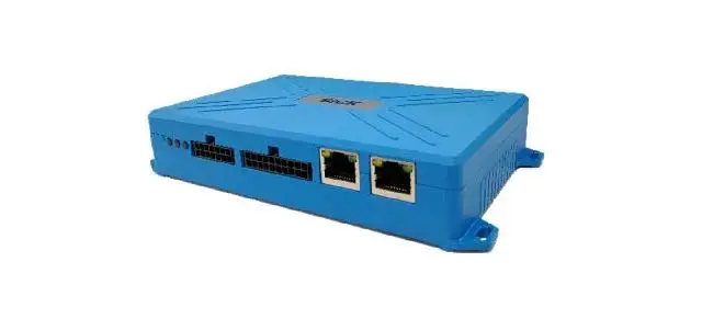
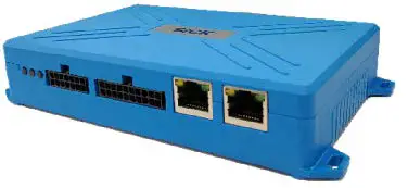
SICK TDC-E210 Telematic Data Collector
Intended use
Telematic Data Collector: (TDC-E210GC, TDC-E210AC), referred to as TDC-E below, is gateway unit for SICK sensors and is used to collect and transfer data from various SICK sensors to a Cloud.
TDC-E is used to collect the data from sensors on various interfaces like Ethernet, CAN, RS-485, RS-422, RS-232, 1-Wire, Digital inputs and outputs and Analog inputs.
TDC-E and accessories may only be operating in accordance with their intended use. In the case of any other usage or in the event of any modifications to the device or to the SICK software, any warranty claims against SICK AG shall be null and void.
About this document
This Quickstart document describes the TDC-E for use with SICK sensors. It contains all the information needed in order to use the device.
Before starting to work with TDC-E, read this Quickstart document carefully and make sure that you are familiar with the device. The information on correct and safe operation of the system presented here will help you avoid personal injury or damage to property.
Additional and other applicable documents
For further information on TDC-E and SICK sensors operation, please refer to the relevant operating instructions.
The TDC-E operating instructions describes the following aspects in detail:
- Physical interfaces and pinout of all connectors
- Installation
- Operation
- Basic functions
The latest Quickstart document as well as the operating instructions can be downloaded from the Internet as follows:
Go to https://sick.com/tdc
- You will find all the documents and additional downloads in this section
- You can also obtain support from your sales partner.
For your safety
It is essential that TDC-E is transported, stored, installed and used in accordance with its intended use in order to ensure error-free, safe operation.
TDC-E may only be installed, operated, used and maintained by appropriately trained, authorized specialist personnel. Specialist personnel are individuals who possess the technical training, knowledge and experience necessary in order to understand the tasks entrusted to them, evaluate these and identify possible hazards.
Precautions
- Do not expose the device to extreme temperature or humidity.
- Do not use or store the device in dusty or dirty areas.
- The antennas shouldn’t come in contact with cables, metal objects, insulation or brackets.
- Do not expose the device to water, rain, splashing water or spilled drinks. It is not waterproof.
- Do not spray anything on and inside the device.
- Dropping, knocking, violently shaking and any rough handling may damage the device.
- Do not transport or store flammable gas, liquid or explosives in the vehicle compartment where the device is installed.
- Before using the device in a vehicle that transports liquefied petroleum gas (such as propane or butane) ensure that the vehicle complies with valid fire and safety regulations of state where the vehicle is used.
- In case of malfunction, contact the authorized service center.
CAUTION
To prevent the risk of electric shock, disconnect power supply from TDC-E when opening the housing for SIM card replacement/installation (if replacement/installation is needed). Other than that, TDC-E housing does not contain any user-serviceable parts.
Installation and commissioning
Scope of delivery
The following components and accessories are supplied with TDC-E:
- Connection cables:
- WireSet – TDC-E PWR power cable
- LTE antenna
- GPS antenna
- WLAN+WPAN antenna
- Quickstart document
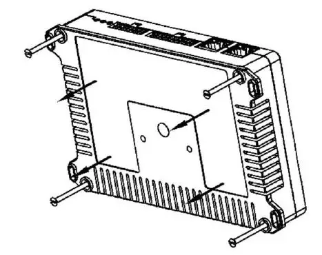
Mounting the TDC-E
Device can be mounted on any sufficiently stable support. To do this, use the mounting holes on the housing of the device.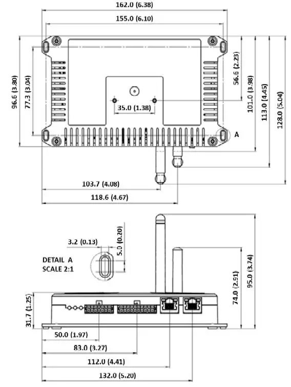
Connecting sensors to the TDC-E
Direct connection
Connect the sensor communication interface to the appropriate connection terminal on the TDC-E device. Use the cables provided with the sensor or additional extension cables if needed.
Installing the power supply
- The power supply (SELV limited, with exact voltage rating) may only be installed by a qualified electrician.
- When working at electrical installations, it is essential to comply with habitual safety requirements.
- If installing in vehicle or on battery, check operating instructions for special installation requirements
To establish the power supply for TDC-E, use a suitable cable (WireSet–TDC-E PWR or WireSet–TDC-E PWR+AIN/DIO) to connect electrical supply to the device’s PWR connector (see Figure 2).
TDC-E does not have its own power switch. To switch off the device, remove the power supply cable from the PWR connector or disconnect the power supply. TDC-E features three LED’s that show the current operating state:
| State | Green LED | Yellow LED | Red LED |
| Device pre-booting | ON | OFF | OFF |
| Device booting | Fast flashing | OFF | OFF |
| Device ready | Hearth beat | OFF | OFF |
| Restoring backup | Fast flashing | Fast flashing | OFF |
| Device reset (factory, data or system reset) | Fast flashing | Fast flashing | OFF |
| Software update | Fast flashing | Fast flashing | OFF |
| Device in error state | OFF | ON | ON |
| User defined under ‘Interfaces’ web page | – | ON/OFF/Heart beat | ON/OFF/Heart beat |
Configuring device
To configure device, access TDC-E Device Manager. TDC-E Device Manager is a local website on device which is used for Device Management. To establish communication with TDC-E, connect TDC-E and PC using ethernet cable. Make sure that PC is in the same subnet as TDC-E. Use any browser (recommended Google Chrome) to access TDC-E Device Manager, by typing web address to browser’s address bar (example for GbE port0 (Eth0): https://192.168.0.100). Create initial user account to manage the device, users or access your services. For further information refer to the operating instructions.
Maintenance and cleaning
Maintenance
TDC-E housing does not contain any user-serviceable parts.
Cleaning
Clean the housing with a soft, dry or slightly moistened cloth. Do not use any solvents or high-pressure cleaners.
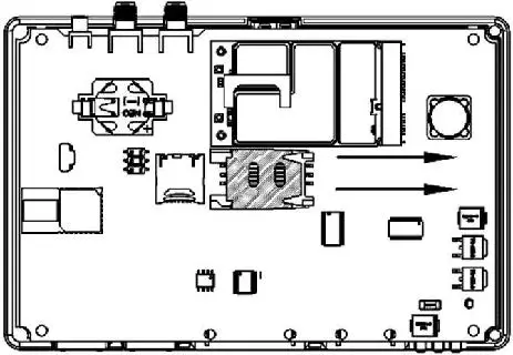
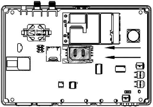
Replacing/installing the SIM card
TDC-E device comes without installed SIM card. If there is a need to install (or replace) the SIM card, follow the lower instructions.
CAUTION
- Always disconnect the device from power supply before replacing/installing the SIM card.
- In all cases, take measures to protect against electrostatic discharge.
Proceed as follows to replace/install the SIM card:
- Make sure that the device is switched off.
- Unscrew and remove the plastic cover on the bottom side of the device.

- Push the plastic cover of the SIM card holder to the side. Orientation is marked on holder with arrow.

- Lift the SIM plastic holder and replace/install the SIM card facing chip side down.

- Return the SIM plastic cover and lock it.
- Return the enclosure plastic cover to the bottom side of the device and secure it with screws.
- Set up APN in TDC-E Device Manager (refer to operating instructions)
Technical data
| Input voltage | 9 V – 36 V DC |
| Max current consumption | 2A Max current consumption |
| Average current consumption | 100 mA @ 24 V (without external load) |
| Protection | Overcurrent, overvoltage and ESD protection (4kV IEC 61000-4-2) |
| Fuse | 4A (internal) |
| Operating temperature | -20 °C to +70°C |
| Storage temperature | -40 °C to +85 °C |
| Case material | PA6 |
| Flammability class | UL 94 V-0 |
| Dimensions without antennas (W×H×L) | 162.0 x 31.7 x 101.0 mm 6.38 x 1.25 x 3.98 inch |
| Protection type | IP20 according to DIN EN 60529 |
| Weight without accessories | 230g |
| GC (Global frequency coverage model)1) | LTE-FDD: 700/800/850/900/1700/1800/1900/2100/2600 LTE-TDD: 1900/2300/2500/2600MHz UMTS: 850/900//1700/1900/2100MHz GSM2): 850/900/1800/1900 MHz Data transfer speed up to 150 Mbps (DL)/50Mbps (UL) for LTE FDD |
| · SIM3) | User replaceable, standard SIM card size (2FF) |
| · Antenna | No cable allowed between antenna and connector |
| · SMS | Text and PDU mode |
| GPS Receiver type | 72-channel u-blox M8 GPS, GLONASS, BeiDou, Galileo Satellite-based augmentation systems L1 C/A: WAAS, EGNOS, MSAS, GAGAN |
| · Sensitivity | -148dBm (acquisition) -164dBm (tracking) |
| · Time to first fix | Hot start: 1 s Warm start: 3 s Cold start: 32 s |
| · Max update rate | 10 Hz |
| · Antenna | Internal and external MCX option Antenna cable is limited to maximum permissible length of <3m |
| WPAN | Dual-Mode: IEEE 802.15.1 |
| WLAN | IEEE 802.11 b/g/n |
- Full 4G performance cannot be guaranteed on operating temperature over 60°C
- Not available for end user
- 3) TDC-E device delivered without SIM card
Interfaces
| TDC-E | Description |
| 6 x AIN (Analog input)1) | •Analog measurement of voltage (0 – 36 V) with accuracy of ±0.2% (+30mV) or current (0 – 32 mA), with accuracy of ±1% (+0.1mA) •Virtual digital input capability (fully configurable high and low voltage levels) •Input resistance 27.5 kΩ typical for voltage mode, 100 Ω typical for current mode |
| 6 x DIO (Digital input/output)1) | •Digital input (high level > 3 V) or digital output (500 mA current capability, 1000 mA is maximal load on all outputs combined, high-side switch outputting voltage from device power input), software configurable, overcurrent protected •Impulse/frequency measurement (high level > 3V) •Input resistance: 22 kΩ typical for digital input |
| 2x DOUT (Additional digital output) | •Additional digital output on LP_A/B pins •Max current of 300 mA |
| 2 x DIN (Additional digital input) | •Additional digital input on CQ_A/B pins |
| 2xEthernet | •2 x RJ45, 10/100/1000 Mbit/s |
| RS-485/RS-4221) | •Fully compliant with ANSI TIA/EIA 485-A •ESD protection (± 6kV IEC 1000-4-2) •Selectable baud rate up to 576 kbps |
| SSI1) | •SSI master interface •Available if RS-485/RS-422 disabled in software1) •Minimum clock rate is restricted to 300 kHz while maximum is 1 MHz |
| RS-232 | •True RS-232 (EIA/TIA-232/V.28) level Receive and Transmit data lines •ESD protection ±8 kV (contact discharge) according to IEC 61000-4-2 •Selectable baud rate up to 250 kbps •Cable is limited to maximum permissible length of <3m. |
| 2xCAN bus | •ISO 11898-2 and ISO 11898-5 compliant •ESD protection ±8 kV (contact discharge) according to IEC 61000-4-2 •Selectable baud rate up to 1 Mbps |
| 1-Wire | •1-Wire interface •28 V overvoltage protection •ESD protection ±4 kV (contact discharge) according to IEC 61000-4-2 •Cable is limited to maximum permissible length of <3m. |
| USB | •USB 2.0 host •Allowed to be used only for storage, with no cable allowed between connector and USB flash drive. •ESD protection ±8 kV (contact discharge) according to IEC 61000-4-2 |
Embedded sensors 1
| TDC -E | Description |
| Accelerometer | •3 axis •Full scale range: ±2g/±4g/±8g •Resolution: up to 0.244 mg •Report rate: 1.56 Hz to 400 Hz |
| Magnetometer | •3 axis •Full scale range: ±12000 mGa •Resolution: up to 1 mGa •Refresh rate: up to 100 Hz |
| Thermometer | •Resolution: ±0.5°C •Accuracy: ±0.5 °C from −20 °C to +100 °C |
Device overview and interfaces 
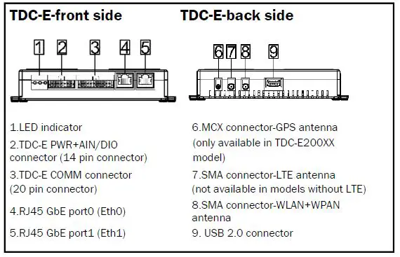
| Port | Default IP address |
| GbE port0 (Eth0) | 192.168.0.100 |
| GbE port1 (Eth1) | by DHCP |
Overview of ports/connectors pinout and design
All ports/connectors are described from side of device. TDC-E PWR+AIN/DIO connector terminals:
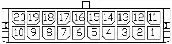 | |||
| Group | Pin | Pin name | Description |
| PWR | 14 | VIN | Power supply for device. Power supply range 9V – 36V DC |
| 7 | GND | Ground pin for power supply | |
|
DIO | 13 | DIO_A | Digital input/output – Channel A |
| 6 | DIO_B | Digital input/output – Channel B | |
| 12 | DIO_C | Digital input/output – Channel C | |
| 5 | DIO_D | Digital input/output – Channel D | |
| 11 | DIO_E | Digital input/output – Channel E | |
| 4 | DIO_F | Digital input/output – Channel F | |
|
AIN | 10 | AIN_A | Analog input – Channel A |
| 3 | AIN_B | Analog input – Channel B | |
| 9 | AIN_C | Analog input – Channel C | |
| 2 | AIN_D | Analog input – Channel D | |
| 8 | AIN_E | Analog input – Channel E | |
| 1 | AIN_F | Analog input – Channel F | |
TDC-E COMM connector terminals:
 | |||
| Group | Pin | Pin name | Description |
| Additional DIO | 20 | LP_A | LP_A pin is used as digital output |
| 10 | CQ_A | CQ_A pin is digital input | |
| Additional DIO | 19 | LP_B | LP_B pin is used as digital output |
| 9 | CQ_B | CQ_B pin is digital input | |
| GND | 18 | GND | GND pin |
| 8 | GND | GND pin | |
| +5V DO | 17 | 5V | 5V digital output |
| 1-WIRE | 7 | 1W | Data pin for 1-WIRE |
|
RS-232 | 16 | TX | Data transmit output pin for RS- 232 protocol |
| 6 | RX | Data receive input pin for RS-232 protocol | |
| 15 | CTS | CTS-Clear to send output pin for RS-232 protocol | |
| 5 | RTS | RTS-Request to send input pin for RS-232 protocol | |
| RS–485/ RS–422/ SSI1) | 14 | Y/CLK+ | Data pin for RS-485/RS-422/SSI |
| 4 | Z/CLK- | Data pin for RS-485/RS-422/SSI | |
| 13 | A/DATA+ | Data pin for RS-485/RS-422/SSI | |
| 3 | B/DATA- | Data pin for RS-485/RS-422/SSI | |
| CAN A | 12 | CANH_A | CAN high data pin – Channel A |
| 2 | CANL_A | CAN low data pin – Channel A | |
| CAN B | 11 | CANH_B | CAN high data pin – Channel B |
| 1 | CANL_B | CAN low data pin – Channel B | |
RS-485/RS-422 Pinout
- Half-duplex mode: Transceiver operates in transmit and receive modes using Y and Z pins.
- Full-duplex mode: Transceiver operates in receive mode on A and B pins and transmit mode on Y and Z pins. For further information refer to the operating instructions.
TECHNICAL INFORMATION
All rights reserved. Subject to change without notice.
Regulatory Compliance Information
These products may only be operated in countries for which approval has been granted.
| No. | Country | Type | Part Number |
| 1 | Singapore | TDC-E210GC | 6070344 |
| 2 | United States | TDC-E210AC | 6079357 |
| 3 | Canada | TDC-E210AC | 6079357 |
Please observe the country-specific information for operation below.
Singapore
Com plies with IMDA Standards DB107198
United States
FCC ID: 2AHDRTDCE210
NOTICE:
This device complies with Part 15. Operation is subject to the following two conditions:
- this device may not cause harmful interference, and
- this device must accept any interference received, including interference that may cause undesired operation.
NOTE:
This equipment has been tested and found to comply with the limits for a Class B digital device, pursuant to Part 15 of the FCC Rules. These limits are designed to provide reasonable protection against harmful interference in a residential installation. This equipment generates, uses and can radiate radio frequency energy and, if not installed and used in accordance with the instructions, may cause harmful interference to radio communications. However, there is no guarantee that interference will not occur in a particular installation. If this equipment does cause harmful interference to radio or television reception, which can be determined by turning the equipment off and on, the user is encouraged to try to correct the interference by one or more of the following measures:
- Reorient or relocate the receiving antenna.
- Increase the separation between the equipment and receiver.
- Connect the equipment into an outlet on a circuit different from that to which the receiver is connected.
- Consult the dealer or an experienced radio/TV technician for help.
NOTICE
Changes or modifications made to this equipment not expressly approved by SICK AG may void the FCC authorization to operate this equipment.
RF Exposure Information
The device complies with FCC radiation exposure limits for an uncontrolled environment. This equipment should be installed and operated with minimum distance 20 cm between the radiator and your body.


