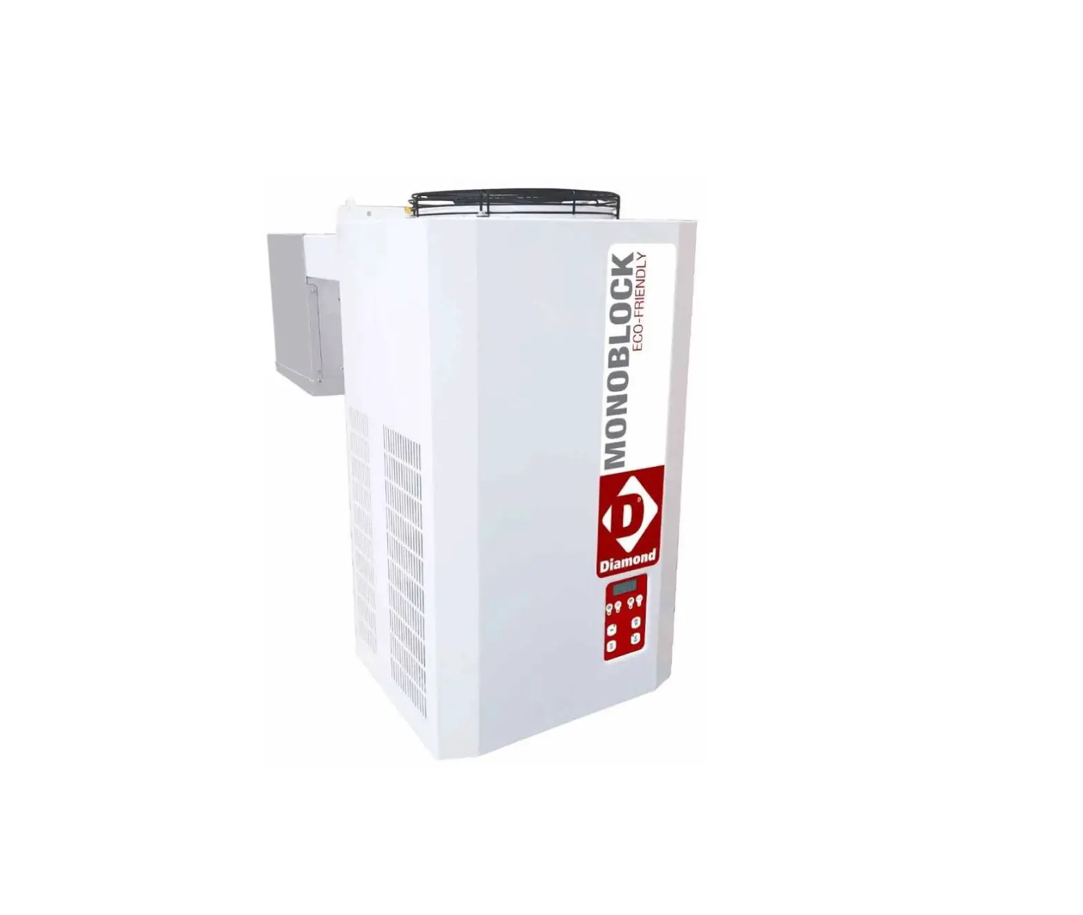
Diamond AP122M-2C Cooling Group
STARTING THE MACHINE
Before starting the Blocksystem, make sure of the following:
- All locking screws are correctly tightened
- All electrical connections have been made correctly.
- The coldroom door is closed so that the door microswitch contact is closed.
Control panel description
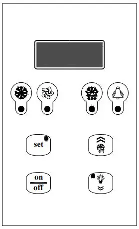
 | Green “COMPRESSOR” LED OFF: The compressor is off LIT: The compressor is operating. BLINKING: The switch on request is pending (delays or protective devices activated) |
| Green “FANS” LED OFF: The fans are off LIT: The fans are operating BLINKING: The switch on request is pending (delays or protective devices activated) | |
| Green “DEFROSTING” LED OFF: Defrosting is not activated LIT: Defrosting is in progress BLINKING: Manual defrosting is in progress; a defrosting request is pending (delays or protective devices activated); network synchronised (master/slave) defrosting |
 | Yellow “ALARM LED” OFF: No alarm is in progress LIT: A serious alarm is in progress (and alarm relay activated) BLINKING: A non-serious alarm is in progress or a serious alarm has been silenced (alarm relay deactivated) |
|
| “SETPOINT” key + “SETPOINT/REDUCED SET” green LED LIT: The setpoint is displayed BLINKING: The reduced set is activated ENTER” key: This is used to set the setpoint, to access the programming menu, and to view the machine status (if held down for 1 second); to enter the programming mode, this key must be held down for 5 seconds. |
 | “UP” key: This is used to command manual defrosting (if held down for more than 5 seconds) as well as to increase the value of the parameter being displayed and to scroll forwards through the menu list. |
 | “ON/OFF” key: This is used as a manual on-off control, to confirm a parameter value and it also allows you to return to the previous menu. To switch the machine on or off, hold this key down for more than 5 seconds. |
 | “DOWN” key: This is used to command the lights manually (if held down for 1 second); it also decreases the value of the parameter being displayed and scrolls back through the menu list. |

Switching on/off
When the machine is energised, the display will read OFF and show the coldroom temperature alternately. To switch the Blocksystem on (off), hold down the “ON/OFF” key on the front of the machine for more than 5 seconds.
Coldroom temperature adjustment
The temperature ranges within which the Blocksystem can operate are as follows:
| Minimum | Maximum | |
| High Temperature (HBP) | +2 | +10 |
| Medium Temperature (MBP) | -5 | +5 |
| Low Temperature (LBP) | -25 | -15 |
The temperature adjustment setpoint can be accessed directly for display or adjustment purposes.
- Press and release SETPOINT: the display will read “SEt” (the procedure is slightly different if there are alarms in progress; see the machine status display paragraph)
- Press SETPOINT: the green SET LED will switch on and the Setpoint value will be displayed
- Press UP or DOWN to set the new value
- Press SETPOINT or ON/OFF (or wait for the 5-second timeout) to confirm the value (the SET LED will switch off and the display will read “SEt”)
- Press ON/OFF (or wait for the 5-second timeout) to return to the normal display mode
How to vary parameters
Blocksystem operation is governed by parameters that have been stored in the memory of the electronic control unit by the manufacturer (see the parameters table). These factory settings should not be varied unless strictly necessary, and in all cases such operations are only to be carried out by qualified staff. Parameters are not only divided by function, they are also divided according to their security/accessibility levels:
Level 0 Setpoint parameters direct access (see paragraph 7.3)
Level 1 frequently used parameters access without password (see paragraph 7.5)
Level 2 configuration parameters access with password (see paragraph 7.7)
Parameters can be varied as follows:
- From the keyboard
- Via LAN network (Master/Slave)
- Via Supervision network
How to vary level 1 parameters
- Hold down SET for 5 seconds until the display reads “reg” (adjustment parameters)
- Press UP or DOWN until the required menu appears on the display
- Press SET to access the menu; the code number for the first parameter in the selected menu will appear
- Press UP or DOWN until the required parameter appears
- Press SET to view the value of the parameter
- Press UP or DOWN to set the required value
- Press SET to confirm the value and return to the parameters list; press ON/OFF to confirm the value and return to the menu list
- Press ON/OFF to pass from the parameters list to the menu list
- Press ON/OFF again to exit the editing procedure,
If no key is pressed for more than 15 seconds, any value shown on the display will be stored in the memory for the relevant parameter and there will be a forced exit from the parameters variation procedure.
Machine status display
- Press and release SET: the display will read “SEt” or “AAL” if there are any alarms in progress
- Press UP or DOWN until the required status is displayed
- AAL alarms in progress (if present)
- SEt setpoint
- Pb1 coldroom temperature probe value
- Pb2 evaporator temperature probe value
- Pb3 probe 3 value (if present)
- Out relay outputs status
- InP digital inputs status
- Press SET to view the value
- For alarm status, output status or input status, press UP or DOWN to scroll through the alarms in progress, the outputs or the inputs,
- Press SET or ON/OFF (or wait for the 5-second timeout) to return to the status list
- Press ON/OFF (or wait for the 5-second timeout) to return to the normal display mode
| Code | Level | Descr. | Range | Unit | ||
| List of -PPS passwords | ||||||
| PPA | Parameters access password Entering a pre-set password will give access to protected parameters | 0 … 255 | ||||
| List of -rEG adjustment parameters | ||||||
| SEt | 0 | Setpoint | LSE …HSE | °C [°F] | ||
| diF | 1 | Differential temperature > setpoint + diff. -> adjustment On temperature ≤ setpoint -> adjustment Off | 0.1 … 50.0 | °C [°F] | ||
| List of -Pro probe parameters | ||||||
| CA1 | 1 | Probe 1 calibration | The value assigned to this parameter is added to (positive value) or taken away from (negative value) the temperature detected by the probe | -20.0 … 20.0 | °C [°F] | |
| CA2 | 1 | Probe 2 calibration | ||||
| CA3 | 1 | Probe 3 calibration | ||||
| List of -CPr compressor parameters | ||||||
| Ont | 1 | Compressor ON time in the event of probe failure | In the event of an adjustment probe error, the compressor is enabled in cyclical mode with set operation and off times. In particular: Ont=0: the compressor remains off Ont>0 and OFt=0: the compressor remains on | 0 … 60 | min | |
| OFt | 1 | Compressor OFF time in the event of probe failure | 0 … 60 | min | ||
| dOn | 1 | Compressor activation delay The time, starting from the switch on request, after which the compressor is effectively activated. In the event of network control in sequential mode, this represents the activation delay from compressor to compressor | 0 … 250 | sec | ||
| dOF | 1 | Minimum compressor OFF time The time, starting from the moment of deactivation, for which it is not possible to restart the compressor | 0 … 60 | min | ||
| dbi | 1 | Delay between switch on times The time, starting from the moment of previous activation, for which the compressor cannot be restarted. | 0 … 60 | min | ||
| OdO | 1 | Outputs delay at power-on (compressor, fans, defrosting) This is used to delay the enabling of adjustments after the instrument has been switched on for a set amount of time. The transition from stand-by to machine activated (ON command from the keyboard) bypasses this delay | 0 … 60 | min | ||
| List of -dEF defrosting parameters | ||||||
| dtY* | 1 | Defrosting type 0 = heating element: ends at temperature or after maximum safe time (timeout) 1 = hot gas: ends at temperature or after maximum safe time (timeout) For defrosting using a heating element, there is a 1 second delay between the compressor switching off and the defrosting relay being triggered | 0,1 | |||
| dit | 1 | Defrosting interval The maximum time (from start to start) between two consecutive defrosting cycles. When this time expires, a defrosting cycle is enabled (cyclical defrosting). The timer is reset at each defrosting request (even if not cyclical). 0 = cyclical defrosting disabled | 0 … 250 | h | ||
| dct | 1 | Defrosting interval count mode 0 = counts if the compressor is operating 1 = counts all the time | 0,1 | |||
| dOH | 1 | Defrosting start delay at power-on The time, as from when the instrument is switched on, for which any defrosting requests are frozen (manual defrosting excluded) | 0 … 250 | min | ||
| dEt* | 1 | Defrosting timeout When the set time expires, defrosting is in any case ended, even if the defrost end temperature has not been reached, passing on to the drip phase | 1 … 250 | min | ||
| dSt* | 1 | Defrost end temperature The probe 2 temperature above which defrosting is ended. If, at the start of a defrosting cycle, the temperature is greater than that set, no defrosting will be carried out. In the event of a probe 2 malfunction, the defrosting cycle will in any case terminate after reaching a time limit | -50.0 … 199.0 | °C [°F] | ||
| Code | Level | Descr. | Range | Unit | ||
| dS2 | 1 | Defrost end temperature for the second evaporator The probe 3 temperature above which defrosting for the second evaporator is ended. If, at the start of a defrosting cycle, the temperature is greater than that set, no defrosting will be carried out. In the event of a probe 3 malfunction, the defrosting cycle will in any case terminate after reaching a time limit. This function is only enabled if P01=3o4, Co4=3 and CP0=2 (alarm relay used for second evaporator defrosting and probe 3 used to detect the temperature of the second evaporator). In this case, the dripping phase will begin after the defrosting cycles of both evaporators have ended. | -50.0 … 199.0 | °C [°F] | ||
| dPO | 1 | Defrosting at power-on 0 = disabled 1 = defrosting when the instrument is switched on | 0,1 | flag | ||
| List of -FAn | fan parameters | |||||
| FSt | 1 | Fans switch on temperature | probe2 ≥ FSt: fans off Fot ≤ probe2 < (FSt – FAd): fans on probe2 < (Fot – FAd): fans off | -50.0 … 199.0 | °C [°F] | |
| Fot | 1 | Fans switch off temperature | -50.0 … 199.0 | °C [°F] | ||
| FAd | 1 | Fans switch on and off differential | 1.0 … 90.0 | °C [°F] | ||
| Fdt | 1 | Post-dripping time The time after the dripping phase, during which the fans remain switched off | 0 … 60 | min | ||
| dt | 1 | Dripping time The time after a defrosting cycle during which the compressor and the evaporator are stopped in order to favour evaporator dripping | 0 … 60 | min | ||
| dFd | 1 | Fans deactivated during defrosting 0 = fans activated (operation set from FPt) 1 = fans deactivated | 0,1 | flag | ||
| FCO | 1 | Fans activated with compressor off 0 = fans deactivated 1 = fans activated (operation set from FPt) 2 = fans in duty cycle operation | 0 … 2 | |||
| Fon | 1 | Fans ON time during duty cycle operation (FCO=2) | 1 … 60 | min | ||
| FoF | 1 | Fans OFF time during duty cycle operation (FCO=2) | 1 … 60 | min | ||
| List of -ALr alarm parameters | ||||||
| AFd | 1 | Temperature alarm threshold differential This sets the re-entry temperature threshold after a high- or low-temperature alarm condition | 1.0 … 90.0 | °C [°F] | ||
| HAL | 1 | Maximum alarm threshold Above this value (absolute or referred to the setpoint) an alarm is triggered If the reference is relative, the unmarked value is added to the setpoint | -50.0 … 199.0 | °C [°F] | ||
| LAL | 1 | Minimum alarm threshold Below this value (absolute or referred to the setpoint) an alarm is triggered If the reference is relative, the unmarked value is subtracted from the setpoint | -50.0 … 199.0 | °C [°F] | ||
| PAO | 1 | Temperature alarm delay at power-on | 0 … 10 | h | ||
| dAO | 1 | Temperature alarm delay after defrost The time, starting from the end of the dripping phase, during which no alarm is signalled. In the event of contemporaneous network defrosting, the time refers to the defrosting end command | 0 … 999 | min | ||
| OAO | 1 | Temperature alarm delay after door closure The time, after the door is closed again and during which no alarm is signalled | 0 … 10 | h | ||
| dAt | 1 | Defrosting alarm timeout enabling This enables the signalling of any defrosting end due to the maximum time limit being reached (timeout). 0 = signal disabled 1 = signal enabled | 0,1 | flag | ||
| List of -diS | display parameters | |||||
| ndt | 1 | Decimal point display 0 = display without decimal point 1 = display with decimal point. | 0,1 | flag | ||
| ddL | 1 | Display during the defrosting phase 0 = normal display (as set from the ddd par.) 1 = freezes the temperature value displayed at the start of defrosting until the end of defrosting and the reaching of the setpoint 2 = “dF” until the end of defrosting and the reaching of the setpoint The ddL parameter can be controlled only if the standard display (ddd par.) includes the adjustment probe (probe 1 or network probe) | 0,1,2 | |||
| Ldd | 1 | Defrosting display block timeout The time, starting from the end of defrosting (end of dripping phase),after which the normal display is in any case restored | 0 … 255 | min | ||
| dro | 1 | °C or °F selection 0 = °C 1 = °F This selection only affects temperature measurements. The values of the parameters concerning temperature maintain their current values and therefore, they must be varied manually to adapt them to the Fahrenheit scale. | 0,1 | flag | ||
| Code | Level | Descr. | Range | Unit |
| List of -CnF configuration parameters | ||||
| LOC (**) | 1 | Keyboard lock 0 = keyboards disabled 1 = main terminal keyboard enabled 2 = secondary terminal keyboard enabled 3 = keyboards enabled (the first to request a service has precedence until completion) | 0 … 3 | |
| rEL | 1 | Software release A read-only value that identifies the software version | 0.0 … 99.9 | |
| List of -Lan(***) network parameters | ||||
| dEA | 1 | Supervision network address (for Master only) The address to be set on each master must take into account the number of slaves present in the LAN network preceding it: “dEA”=”dEA[previous master]”+”L01[previous master]”+1 The Supervision network address for a Slave is “dEA[master]”+”L00”) | 1 … 199 |
(*) For models
PTM068Z012,PTM080Z012,PTL060Z012,PTL080Z012,PTM110Z012,PTM140Z012,PTM200Z012,PTL130Z012,PTL1
80Z012,PTL200Z012,PTL260Z012,PTM300Z012, PTM370Z012, PTL350Z012 and PTL450Z012, the dtY,dEt and dSt
parameters have the following values (Defrosting by heater):
| dtY | 1 | Defrosting type 0 = heating element: ends at temperature or after maximum safe time (timeout) 1 = hot gas: ends at temperature or after maximum safe time (timeout) For defrosting using a heating element, there is a 1 second delay between the compressor switching off and the defrosting relay being triggered | 0,1 | |
| dEt | 1 | Defrosting timeout (Defrosting by heater) When the set time expires, defrosting is in any case ended, even if the defrost end temperature has not been reached, passing on to the drip phase | 1 … 250 | min |
| dSt | 1 | Defrost end temperature (Defrosting by heater) The probe 2 temperature above which defrosting is ended. If, at the start of a defrosting cycle, the temperature is greater than that set, no defrosting will be carried out. In the event of a probe 2 malfunction, the defrosting cycle will in any case terminate after reaching a time limit | -50.0 … 199.0 | °C [°F] |
Note : To release the keypad, hold down “SET” and “ON/OFF” together for at least 5 seconds.
Note : The “LAn” network parameter only serves in the event of MASTER/SLAVE or REMOTE CONTROL operation
ADVANCED ELECTRONIC CARD PROGRAMMING FOR BLOCKSYSTEM
Level 2 programming
The procedure for editing level 2 parameters is protected by a password and can be carried out in the following manner: enter the programming mode by holding down the “set” key for at least 7 seconds until the display reads “reg”, which corresponds to the adjustment parameters directory, then proceed as follows:
- Press the “down” key (the display will read “PPS”)
- Press the “set” key (the display will read “PPA”)
- Press the “set” key again (the display will read “0”)
- Press the “up” key until the display reads 22 (the level 2 password)
- Press the “set” key to confirm the password
At this point, using the “up” and “down” keys, you can access all of the electronic card parameters shown in the annexed programming chart.
Once you have edited the required parameters, press the “ON/OFF” key twice until the display shows the cold room temperature (or wait for 15 seconds without pressing any keys); this way the edited parameters will be stored to the memory.
CAUTION!
THE FOLLOWING SECTION EXPLAINS THE NECESSARY PROCEDURE IN THE EVENT THAT PARAMETERS ARE EDITED WITHOUT FOLLOWING ANY CRITERIA OR THAT THE CARD SETTINGS ARE LOST. IN ANY CASE, WE ADVISE THAT YOU FOLLOW THESE STEPS ONLY AFTER THE APPROVAL OF A RIVACOLD TECHNICAL ENGINEER.
Restoring the factory settings
CAUTION: the following procedure will restore all factory settings for the electronic card. We advise that you only do this if strictly necessary and in any case, that you are assisted by a technical engineer from Rivacold.
Cut off the power to the Blocksystem.
Press the “set” and “down” keys at the same time, then switch the Blocksystem on again while holding down these keys.
Release the keys when the display reads “–˜3”.
At this point, the electronic card will re-start and its parameters will have returned to those set in the factory. The display will read “Um” for 1 second; it will then show the temperature read by the cold room probe.
PLEASE NOTE: THIS OPERATION RESTORES THE FACTORY SETTINGS FOR A MEDIUM-TEMPERATURE MACHINE APPLICATION (-5/+5°C) WITH “HOT GAS” DEFROSTING.
IF YOU ARE USING AN APPLICATION OTHER THAN “MEDIUM TEMPERATURE” AND/OR A DIFFERENT TYPE OF DEFROSTING (NOT “HOT GAS”), YOU MUST FOLLOW THE INSTRUCTIONS IN THE FOLLOWING SECTION, AND REFER TO THE “CPP PARAMETER PROGRAMMING CHART”.
Rapid programming according to the application required
Level 2 programming contains a parameter known as “CPP” (to be found in the “cnf” directory) which is used for the rapid programming of parameters according to application and defrosting types (see following chart).
CPP parameter programming chart
| Defrosting | Hot gas | Hot gas | Fan | Heating element | Heating element | |
| Application | -5/+5°C | -25/-15°C | +2/+10°C | -5/+5°C | -25/-15°C | |
| Menu | Code no. | CPP=1 | CPP=2 | CPP=3 | CPP=4 | CPP=5 |
| REG | SEt | 2.0 | -18.0 | 5.0 | 2.0 | -18.0 |
| REG | diF | 2.0 | 2.0 | 2.0 | 2.0 | 2.0 |
| REG | HSE | 5.0 | -15.0 | 10.0 | 5.0 | -15.0 |
| REG | LSE | -5.0 | -25.0 | 2.0 | -5.0 | -25.0 |
| DEF | dtY | 1 | 1 | 0 | 0 | 0 |
| DEF | dEt | 15 | 15 | 15 | 30 | 30 |
| DEF | dSt | 10.0 | 15.0 | 10.0 | 15.0 | 15.0 |
| Fan | FSt | 8.0 | -5.0 | 50.0 | 8.0 | -5.0 |
| Fan | Fdt | 1 | 2 | 0 | 1 | 2 |
| Fan | dt | 2 | 2 | 0 | 2 | 2 |
| Fan | dFd | 1 | 1 | 0 | 1 | 1 |
Follow the instructions in paragraph 1 to access level 2 programming
- Press the “up” or “down” keys until you reach the “CnF” directory
- Press the “set” key (the LOC parameter will appear)
- Press the “up” key until you reach the “CPP” parameter
- Press the “set” key (the number 0 will appear)
- Press the “up” key until you reach the number corresponding to the required program Then press the “set” key to confirm.
ALARM SIGNALS
In the event of an alarm, the card normally activates the following:
- The relevant alarm code is shown on the display. In particular, the control alternates the alarm code and the temperature that is normally shown on the display; if there is more than one alarm, they are displayed in succession, alternated with the temperature
- The alarm LED is switched on
- The alarm relay is triggered.
Code displayed Description/Control LED enable Relay enable Reset Mode
| E1 | cold room probe temperature error if a probe is used for adjustment, the compressor will be activated cyclically and defrosting cycles will be disabled; if a balanced network probe is enabled, adjustment will continue, bypassing the malfunctioning probe | yes | yes | automatic when the condition ceases |
| E2 | End defrostin probe g error defrosting will end due to timeout | yes | yes | automatic when the condition ceases |
| E3 | 3rd probe error (condenser temperature) the associated controls are disabled | blink. | no | automatic when the condition ceases |
| 3rd probe error (2nd evaporator temperature) defrosting will end due to timeout | yes | yes | ||
| heat alarm (*) adjustment is disabled | yes | no | automatic when the condition ceases | |
| HP pressure switch alarm(*) adjustment is disabled | yes | no | automatic when the condition ceases | |
| LP pressure switch alarm(*) adjustment is disabled | yes | no | automatic when the condition ceases | |
| E4 | repeated heat alarm adjustment is disabled permanently | yes | yes | at switch on |
| E5 | repeated HP pressure switch alarm adjustment is disabled permanently | yes | yes | at switch on |
| E6 | repeated LP pressure switch alarm adjustment is disabled permanently | yes | yes | at switch on |
| LO | low temperature alarm | yes | yes | automatic when the condition ceases |
| HI | high temperature alarm | yes | yes | automatic when the condition ceases |
| EE | data saving alarm default parameters are loaded | yes | yes | at power-on or after the parameter has been stored to memory |
| Ec | condenser cleaning alarm | blink. | no | automatic when the condition ceases |
| Er | network alarm (**) | yes | yes | automatic when the condition ceases |
| Ed | defrosting timeout alarm | blink. | no | automatic at the start of the next defrost |
| Od | door open timeout alarm normal operation is enabled again | blink. | no | automatic when the condition ceases |
| nx | slave x alarm (on master only) | yes | progr. | automatic when the condition ceases |
| Ux | slave x not connected (on master only) the slave is not controlled | blink. | no | automatic when the condition ceases |
| u0 | master not connected (on slave only) the slave is released from the network and operates autonomously | blink. | no | automatic when the condition ceases |
| dx | slave x download failed(on master only) | blink. | no | manual or automatic when the condition ceases |
There is no reading on the display.
(**) Network alarms are where, subsequent to programming, the alarm command is communicated from the master to all network devices, in the event that the alarm relay is triggered on the master itself
During operation, in specific conditions the following signals are displayed:
| Code displayed | Description | Notes |
| OFF | unit in stand-by (operation disabled) | remains until the next ON command |
| dF | defrosting in progress | see par. “ddL” |
| dFu | defrosting not performed | displayed for 2 seconds when the defrosting command is not performed because the evaporator temperature is already above the defrosting end temperature (parameter dst) |
| uM | master unit | at switch on, the network configuration of the unit is displayed |
| uSx | slave x unit | |
| Cn | terminal/control connection interrupted | the terminal is not receiving data from the control |
If the terminal/control connection does not operate correctly at switch on, the terminal display will read “88,8” and the LEDs will all be switched off.
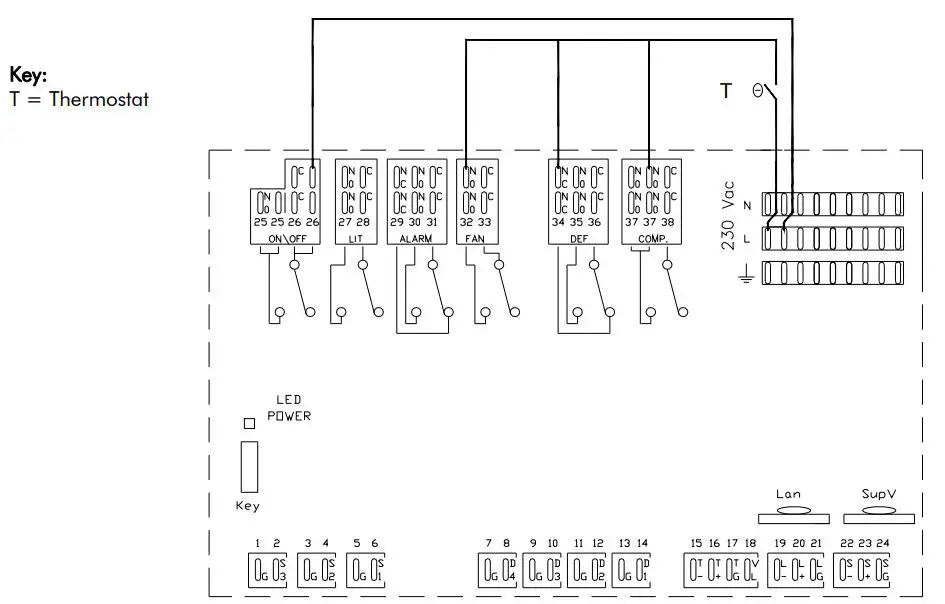
EMERGENCY SYSTEM
PLEASE NOTE: A specialist technical engineer must only perform the operations described here below.
If the electronic control unit breaks down or presents operating anomalies and it is impossible to replace it immediately, there is an EMERGENCY SYSTEM that can be used to maintain the unit in operation until it can be replaced.
To use this system, proceed as follows:
- Cut off power to the Blocksystem
- Remove all jumpers between the L terminals and the common contacts of the card relays (terminals 25-28-33-36-38)
- As shown in the diagram, connect a thermostat between the L terminal, the NO terminals (terminals 32,37) and the NC terminal (terminal 34) of the compressor, defrosting and fan relays (COMP, DEF and FAN)
- Fit a jumper between the L terminal and the NO terminal of the ON/OFF relay (terminal 26 supplying power to the crankcase heaters, door and waste, where fitted).
- Connect the Blocksystem back to the mains power, setting the thermostat to the required temperature.
- PLEASE NOTE: This connection can only be used momentarily. Contact your dealer as soon as possible to replace the malfunctioning card.
- PLEASE NOTE: Defrosting will be cut out for the entire emergency phase and for this reason, we
recommend that cold room door opening be kept to a minimum. - When fitting the new control unit, restore all of the connections described in points 2,3,4 and 5.