
STANLEY HP210 HYDRAULIC POWER UNIT User Manual
SAFETY SYMBOLS
Safety symbols and signal words, as shown below, are used to emphasize all operator, maintenance and repair which
![]() This is the safety alert symbol. It is used to alert you to potential personal injury hazards. Obey all safety messages that follow this symbol to avoid possible injury or death.
This is the safety alert symbol. It is used to alert you to potential personal injury hazards. Obey all safety messages that follow this symbol to avoid possible injury or death.
![]() Danger: This safety alert and signal word indicates an imminently hazardous situation which, if not avoided, will result in death or serious injury.
Danger: This safety alert and signal word indicates an imminently hazardous situation which, if not avoided, will result in death or serious injury.
![]() Warning; This safety alert and signal word indicates a potentially hazardous situation which, if not avoided, could result in death or serious injury.
Warning; This safety alert and signal word indicates a potentially hazardous situation which, if not avoided, could result in death or serious injury.
![]() Caution: This safety alert and signal word indicates a potentially hazardous situation which, if not avoided, could result in death or serious injury.
Caution: This safety alert and signal word indicates a potentially hazardous situation which, if not avoided, could result in death or serious injury.
Caution: This signal word indicates a potentially hazardous situation which, if not avoided, may result in property damage.
Notice: This signal word indicates a situation which, if not avoided, will result in damage to the equipment.
Important: This signal word indicates a situation which, if not avoided, may result in damage to the equipment.
Always observe safety symbols. They are included for your safety and for the protection of the tool.
LOCAL SAFETY REGULATIONS
Enter any local safety regulations here. Keep these instructions in an area accessible to the operator and maintenance personnel.
Safety Precautions
Tool operators and maintenance personnel must always comply with the safety precautions given in this manual and on the stickers and tags attached to the equipment. These safety precautions are given for your safety. Review them carefully before operating the tool and before performing general maintenance or repairs.
Supervising personnel should develop additional precautions relating to the specific work area and local safety regulations. If so, place the added precautions in the space provided on .
In addition to this manual, read and understand safety and operating instructions in the engine “Operation & Maintenance Instructions” manual furnished with the HP210 power unit.
The HP210 will provide safe and dependable service if operated in accordance with the instructions given in this manual. Read and understand this manual and any stickers and tags attached to the unit. Failure to do so could result in personal injury or equipment damage.
- Operator must start in a work area without bystanders. The operator must be familiar with all prohibited work areas such as excessive slopes and dangerous terrain conditions.
- Establish a training program for all operators to ensure safe operation.
- Do not operate the power unit unless thoroughly trained or under the supervision of an instructor.
- Always wear safety equipment such as goggles, ear protection, head protection and safety shoes at all times when operating the power unit.
- Do not inspect or clean the power unit while it is running. Accidental engagement of the unit can cause serious injury.
- Always use hoses and fittings rated at 2500 psi/172 bar with a 4-to-1 safety factor. Be sure all hose connections are tight.
- Be sure all hoses are connected for correct flow direction to and from the tool being used.
- Do not inspect hoses and fittings for leaks by using bare hands. “Pin-hole” leaks can penetrate the skin.
- NEVER OPERATE THE POWER UNIT IN A CLOSED SPACE. Inhalation of engine exhaust can be fatal.
- Do not operate a damaged or improperly adjusted power unit.
- Never wear loose clothing that can become entangled in the working parts of the power unit.
- Keep all parts of your body away from the working parts of the power unit.
- Keep dear of hot engine exhaust.
- Do not add fuel to the power unit while it is running or is still hot.
- Do not operate the power unit if gasoline odor is present.
- Do not use flammable solvents around the power unit engine.
- Do not operate the power unit within 3.3 ft/1 m of buildings, obstructions or flammable objects.
- Do not reverse tool rotation direction by changing fluid flow direction.
- Allow power unit engine to cool before storing in an enclosed space.
- Always keep critical tool markings, such as labels and warning stickers, legible.
- To avoid personal injury or equipment damage, all tool repair, maintenance and service must only be performed by authorized and properly trained personnel.
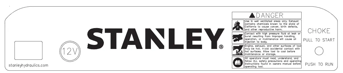


28322 CE Decal
HP210BA
HP210BBA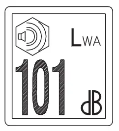
66653 Sound Power Decal
HP210BA
HP210BBA
73306 Lifting Point Decal
HP210BA
HP210BBA
Hose Types
The rated working pressure of the hydraulic hose must be equal to or higher than the relief valve setting on the hydraulic system. There are three types of hydraulic hose that meet this requirement and are authorized for use with Stanley hydraulic tools. They are:
Certified non-conductive — constructed of thermoplastic or synthetic rubber inner tube, synthetic fiber braid reinforcement, and weather resistant thermoplastic or synthetic rubber cover. Hose labeled certified non-conductive is the only hose authorized for use near electrical conductors.
Wire-braided (conductive) — constructed of synthetic rubber inner tube, single or double wire braid reinforcement, and weather resistant synthetic rubber cover. This hose is conductive and must never be used near electrical conductors.
Fabric-braided (not certified or labeled non-conductive) — constructed of thermoplastic or synthetic rubber inner tube, synthetic fiber braid reinforcement, and weather resistant thermoplastic or synthetic rubber cover. This hose is not certified non-conductive and must never be used near electrical conductors.
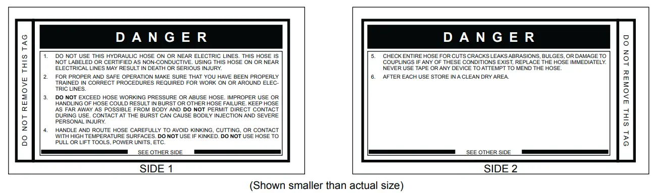
HOSE SAFETY TAGS
To help ensure your safety, the following DANGER tags are attached to all hose purchased from Stanley. DO NOT REMOVE THESE TAGS. If the information on a tag is illegible because of wear or damage, replace the tag immediately. A new tag may be obtained from your Stanley Distributor.
The tag shown below is attached to “Certified non-conductive” Hose
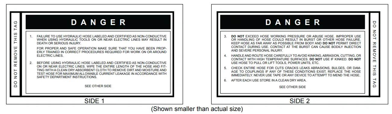
The tag shown below is attached to “Conductive” Hose
HOSE RECOMMENDATION
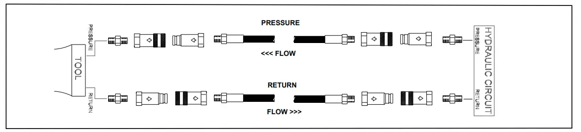
Figure 1. Typical Hose Connections
Tool to Hydraulic Circuit Hose Recommendations
The chart to the right shows recommended minimum hose diameters for various hose lengths based on gallons per minute (GPM)/liters per minute (LPM). These recommendations are intended to keep return line pressure (back pressure) to a minimum acceptable level to ensure maximum tool performance.
This chart is intended to be used for hydraulic tool applications only based on Stanley tool operating requirements and should not be used for any other applications.
All hydraulic hose must have at least a rated minimum working pressure equal to the maximum hydraulic system relief valve setting.
All hydraulic hose must meet or exceed specifications as set forth by SAE J517.
| Oil Flow | Hose Lengths | Inside Diameter | USE (Press/Return) | Min. Working Pressure | ||||
| GPM | LPM | FEET | METERS | INCH | MM | PSI | BAR | |
| Certified Non-Conductive Hose – Fiber Braid – for Utility Bucket Trucks | ||||||||
| 4-9 | 15-34 | up to 10 | up to 3 | 3/8 | 10 | Both | 2250 | 155 |
| Conductive Hose – Wire Braid or Fiber Braid -DO NOT USE NEAR ELECTRICAL CONDUCTORS | ||||||||
| 4-6 | 15-23 | up to 25 | up to 7.5 | 3/8 | 10 | Both | 2500 | 175 |
| 4-6 | 15-23 | 26-100 | 7.5-30 | 1/2 | 13 | Both | 2500 | 175 |
| 5-10.5 | 19-40 | up to 50 | up to 15 | 1/2 | 13 | Both | 2500 | 175 |
| 5-10.5 | 19-40 | 51-100 | 15-30 | 5/8 | 16 | Both | 2500 | 175 |
| 5-10.5 | 19-40 | 100-300 | 30-90 | 5/8 | 16 | Pressure | 2500 | 175 |
| 3/4 | 19 | Return | 2500 | 175 | ||||
| 10-13 | 38-49 | up to 50 | up to 15 | 5/8 | 16 | Both | 2500 | 175 |
| 10-13 | 38-49 | 51-100 | 15-30 | 5/8 | 16 | Pressure | 2500 | 175 |
| 3/4 | 19 | Return | 2500 | 175 | ||||
| 10-13 | 38-49 | 100-200 | 30-60 | 3/4 | 19 | Pressure | 2500 | 175 |
| 1 | 25.4 | Return | 2500 | 175 | ||||
| 13-16 | 49-60 | up to 25 | up to 8 | 5/8 | 16 | Pressure | 2500 | 175 |
| 3/4 | 19 | Return | 2500 | 175 | ||||
| 13-16 | 49-60 | 26-100 | 8-30 | 3/4 | 19 | Pressure | 2500 | 175 |
| 1 | 25.4 | Return | 2500 | 175 | ||||
HTMA/EHTMA REQUIREMENTS
HTMA/EHTMA REQUIREMENTS
| Flow Range Nominal Operating Pressure (at the power supply outlet) | 4-6 gpm (15-23 lpm) 1500 psi (103 bar) | 7-9 gpm (26-34 lpm) 1500 psi (103 bar) | 9-10.5 gpm (34-40 lpm) 1500 psi (103 bar) | 11-13 gpm (42-49 lpm) 1500 psi (103 bar) |
| System relief valve setting (at the power supply outlet) | 2100-2250 psi (145-155 bar) | 2100-2250 psi (145-155 bar) | 2200-2300 psi (152-159 bar) | 2100-2250 psi (145-155 bar) |
| Maximum back pressure (at tool end of the return hose) | 250 psi (17 bar) | 250 psi (17 bar) | 250 psi (17 bar) | 250 psi (17 bar) |
| Measure at a max. fluid viscosity of(at min. operating temperature) | 400 ssu* (82 centistokes) | 400 ssu* (82 centistokes) | 400 ssu* (82 centistokes) | 400 ssu* (82 centistokes) |
| Temperature: Sufficient heat rejection capacity to limit max. fluid temperature to: (at max. expected ambient temperature) | 140° F (60° C) | 140° F (60° C) | 140° F (60° C) | 140° F (60° C) |
| Min. cooling capacity at a temperature difference of between ambient and fluid temps. NOTE: Do not operate the tool at oil temperatures above 140° F (60° C). Operation at higher temperatures can cause operator discomfort at the tool. | 3 hp (2.24 kW) 40° F (22° C)
| 5 hp (3.73 kW) 40° F (22° C) | 6 hp (5.22 kW) 40° F (22° C) | 7 hp (4.47 kW) 40° F (22° C) |
| Filter Min. full-flow filtration Sized for flow of at least: (For cold temp. startup and max. dirt-holding capacity) | 25 microns 30 gpm (114 lpm) | 25 microns 30 gpm (114 lpm) | 25 microns 30 gpm (114 lpm) | 25 microns 30 gpm (114 lpm) |
| Hydraulic fluid Petroleum based (premium grade, anti-wear, non-conductive) Viscosity (at min. and max. operating temps) NOTE: When choosing hydraulic fluid, the expected oil temperature extremes that will be experienced in service determine the most suitable temperature viscosity characteristics. Hydraulic fluids with a viscosity index over 140 will meet the requirements over a wide range of operating temperatures. *SSU = Saybolt Seconds Universal | 100-400 ssu* | 100-400 ssu* (20-82 centistokes) | 100-400 ssu* | 100-400 ssu* |
EHTMA HYDRAULIC SYSTEM REQUIREMENTS
| EHTMA HYDRAULIC SYSTEM REQUIREMENTS | CLASSIFICATION | ||||
 |  |  | |||
| Flow Range | 3.5-4.3 gpm (13.5-16.5 lpm) | 4.7-5.8 gpm (18-22 lpm) | 7.1-8.7 gpm (27-33 lpm | 9.5-11.6 gpm (36-44 lpm) | 11.8-14.5 gpm (45-55 lpm) |
| Nominal Operating Pressure (at the power supply outlet) | 1870 psi (129 bar) | 1500 psi (103 bar) | 1500 psi (103 bar) | 1500 psi (103 bar) | 1500 psi (103 bar) |
| System relief valve setting (at the power supply outlet) | 2495 psi (172 bar) | 2000 psi (138 bar) | 2000 psi (138 bar) | 2000 psi (138 bar) | 2000 psi (138 bar) |
NOTE: there are general hydraulic system requirements. See tool Specification page for tool specific requirements.
OPERATION
PREPARATION FOR USE
Do not operate HP210 until you have completed the following steps:
READ THE ENGINE “OPERATING & MAINTENANCE INSTRUCTIONS” MANUAL.
CHECK ENGINE CRANKCASE OIL LEVEL
Check the oil level before starting the engine. Make sure the oil level is at the FULL MARK on the dipstick. Do not overfill. Use detergent oil classified “For Service SE, SF, SG” as specified in the engine “Operating & Maintenance Instructions” manual. See the “Operating & Maintenance Instructions” manual for oil viscosity grade.
CHECK ENGINE FUEL LEVEL
If fuel level is low, fill with unleaded gasoline (85 octane minimum).
CHECK HYDRAULIC FLUID
Ensure there is hydraulic fluid in the hydraulic oil tank. Below is a list of recommended oils.
| Brand | Biodegradable | Description |
| CITGO | No | Hydurance AW32 |
| AMS Oil | No | HVH 32 |
| Exxon Mobil | No | Univis HVI26* |
| Exxon Mobil | No | DTE 10 Excel |
| Shell | No | S2 V 32 |
| Chevron | No | Rando HDZ 32 |
| Conoco Phillips | No | Unax AW-WR-32 |
| Clarion (CITGO) | Yes | Green Bio 32 |
| Exxon Mobil | Yes | EAL 224H |
| Chevron | Yes | Clarity AW32 |
| Terresolve | Yes | Envirologic 132 |
| Shell | Yes | Naturelle HF-E-32 |
*Recommended for extreme cold temperatures
INSTALL HYDRAULIC CONNECTIONS
STANLEY recommends you use hose lengths of 25 ft/8 m with 1/2 inch/12.7 mm inside diameter. Hoses must have a working pressure rating of at least 2500 psi/175 bar. Hose ends must have male threads compatible with H.T.M.A. quick disconnect fittings (NPT).
H.T.M.A. approved quick disconnect couplings are installed to hydraulic hoses so that the direction of oil flow is always from the male to the female coupling. Additional fittings, such as reducers or adapter fittings, are not required.
If adapter fittings are used, they must be approved steel hydraulic fittings meeting a minimum operating pressure rating of 2500 psi/172 bar. Do not use galvanized pipe fittings or black pipe fittings.
Use thread tape or pipe joint compound when installing quick disconnect couplings to hose or tool fittings. Follow the instructions furnished with the selected thread sealant. DO NOT OVERTIGHTEN THE FITTINGS.
USING THE 12 VOLT DC OUTLET
A 12 VDC outlet is available for specific models. The DC outlet is ON at all times.
Important: Accessories left in the 12VDC outlet can drain the battery if the HP210 is not running.
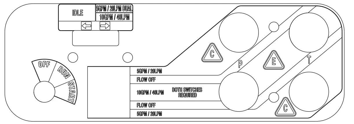
CONTROLS
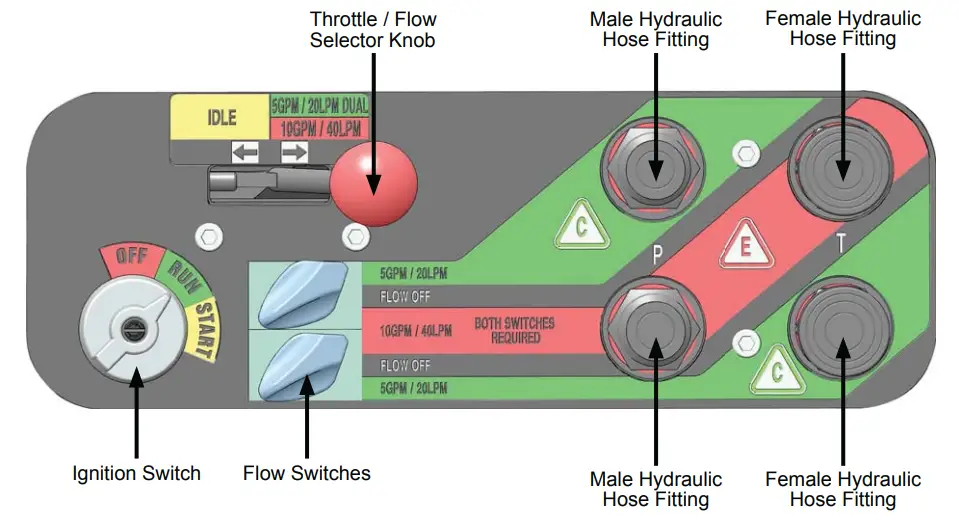
HP210 can provide two 5 GPM/20 LPM circuits (up to 2000 psi/140 bar) or one 10 GPM/40 LPM circuit (up to 2000 psi/140 bar).
STARTUP
- Toggle both Flow Switches to the “FLOW OFF” position.
Note: HP210 will not start unless the Flow Switches are in the “FLOW OFF” position. - Pull the choke knob out
- Select the desired flow using the Flow Selector Knob.
- Turn the Ignition Switch to the “START” position. After the engine starts, release the switch.
- Gradually push in the choke knob as the engine begins to idle smoothly.
- Allow the engine to warm up.
- Connect hoses and the tool.
- Toggle the Flow Switches to the desired flow for each circuit.
CHANGING CIRCUIT FLOW
- Toggle the Flow Switches to the “FLOW OFF” position.
- Select the desired circuit flow using the Flow Selector Knob.
- Toggle the Flow Switches to the desired flow for each circuit.
SHUTDOWN
- Toggle the Flow Switches to the “FLOW OFF” position.
- Allow the engine to idle for approximately one minute.
- Turn the Ignition Switch to the “OFF” position.
COLD WEATHER STARTUP
Hydraulic fluid becomes thicker in cold weather. STANLEY recommends that the engine be run at a low idle (5 GMP/20 LPM setting) long enough to bring the fluid temperature up to a minimum of 50°F/10°C. Allow the hydraulic fluid to circulate through the tool hoses until they are warm.
Once the hydraulic oil is warm, you may operate the HP210 as normal.
MAINTENANCE & TESTING
ENGINE MAINTENANCE SCHEDULE
Follow the maintenance instructions provided in the engine “Operating & Maintenance Instructions” manual.
HYDRAULIC SYSTEM MAINTENANCE
- Check hydraulic fluid level daily and fill if needed.
- Check hydraulic lines and fittings daily for leaks, kinks or damage. Do not use your hand to perform this check.
Remove condensed moisture from the hydraulic fluid
- Set the flow selector to a 5 GPM/20 LPM circuit flow.
- Start the engine and pump the fluid, out of the pressure port, into a 5 gal. container.
- When hydraulic tank is empty, turn the Ignition Switch to the “Off” position.
- Let the water settle to the bottom of the container.
- Pour the hydraulic fluid back into the tank, being careful to not disturb the water sitting at the bottom of the container.
Change the hydraulic filter every 200 hours of operation. Change more often if used in cold, moist or dusty conditions.
Check oil cooler. Remove debris with air pressure.
BATTERY
- Do not charge the battery with an automotive battery charger. Charging at higher than 2 amps will damage the battery.
- If the engine stalls during operation, set the Ignition Switch to the “OFF” position to preserve battery charge.
STORAGE
- Clean the unit thoroughly. Do not pressure wash.
- Always store the unit in a clean and dry location.
- If storing for over 30 days, add an additive to the fuel tank to prevent the fuel from gumming. Run the engine to circulate the additive.
- Replace the crankcase oil.
GENERAL
Tests should be performed periodically to ensure HP210 is operating at maximum efficiency. Stanley Circuit Tester (part number 04182) can be used to isolate problems in both the engine and hydraulic system.
TESTING THE HYDRAULIC CIRCUIT
Test to ensure the hydraulic pump is supplying the correct flow and pressure, and that the system relief valve is operating properly. Before testing, make sure the engine is warm and operating smoothly.
- Turn the Flow Switch to the “FLOW OFF” position.
- Set the Flow Selector Knob to the flow you would like to test.
- Connect the Stanley Circuit Tester to the tool hoses.
- Fully open the tester restrictor valve (counterclockwise).
- Start the engine.
- The test flow gauge should read +/- 1 GPM of the selected flow.
- Slowly turn the restrictor valve clockwise while watching the pressure gauge. The flow rate should not change as the pressure reaches 2100-2200 psi/148- 155 bar.
- At 2100-2200 psi/148-155 bar, the relief valve should begin to open. The flow rate should start to drop because the relief valve is allowing fluid to bypass to the hydraulic fluid tank. The relief valve is preset at the factory. If it does not open within the above range, the relief valve must be reset as follows:
a. The relief valve is located on the right side of the unit, behind the dash panel (10, page 16). Use a wrench to loosen the nut on the relief valve.
b. Use an Allen wrench to adjust the relief valve. Turn clockwise to raise the opening pressure, and counterclockwise to reduce the opening pressure.
c. Tighten the nut and repeat the test.
TROUBLESHOOTING
| Problem | Cause | Remedy |
| Engine will not start. | Flow Switch is not in the “FLOW OFF” position. | Make sure the Flow Switch is in the “FLOW OFF” position before attempting to start the power unit. |
| Battery is not connected. | Check the battery cables for continuity and re-attach to the battery. | |
| Weak battery charge. | Test the battery voltage and charge if necessary. If the battery will not hold a charge, replace. | |
| No Fuel. | Ensure the power unit is cool, then add fuel. | |
| Fuel filter is plugged. | Replace the fuel filter. | |
| Defective spark plugs. | Remove the spark plugs and check the gap. Replace if necessary. | |
| Hydraulic fluid is blowing out of the fluid reservoir vent. | Hydraulic fluid tank is overfilled. | Remove hydraulic fluid from the tank. |
| Hydraulic pump is leaking. | Check the pump connections (see page 20. Tighten if necessary. | |
| The hydraulic tool connected to the power unit will not operate. | The Flow Selector Knob is not in the proper position for the connected tool. | Ensure that the Flow Selector Knob is positioned for the correct fluid flow for your tool. |
| The tool is not properly connected to the power unit. | Check the connection hoses from the power unit to the tool. Ensure the pressure and the return hoses are in the proper ports on the tool. | |
| The quick disconnect fittings are defective. | Disconnect the fittings from the hose and ensure there is free flow from each end of the fittings. | |
| The hydraulic fluid level in the reservoir is too low. | Check the fluid level in the hydraulic fluid tank. Add more fluid if necessary. | |
| The pump coupling is defective. | Power down the unit and check the coupling between the hydraulic pump and the engine (10, page 18). | |
| The relief valve is stuck open. | Adjust the valve or replace if necessary. | |
| Suction hoses are kinked. | Visually check the suction hose for a kink. The hose should have a smooth curve. | |
| The solenoid is not working. | Check electrical connections (see page 21). Replace if necessary. | |
| The attached tool is defective. | Refer to the tool manual. |
SPECIFICATIONS
- Engine: 18 hp Briggs
- Capacity (Flow): Two 5 GPM/20 LPM Circuits or One 10 GPM/40 LPM Circuit
- Length: 36 in. / 91.4 cm
- Width:23 in: / 58.4 cm
- Height: 29.5 in. / 74.9cm
- Weight (Wet): Dual Circuit Briggs: 334 lbs / 151.5 kg
- Fuel Tank Capacity: : 5.5 gal. / 20.8 ltr
- Estimated Gas Consumption Per Hour: 1.3 gal / 4 ltr
- Hydraulic Reservoir Capacity: : 3 gal. / 11 ltr
- Nominal Operating Pressure : 1500 psi / 103 bar
- Relief Valve “crack” setting: 2100 psi / 145 bar
- Full relief setting: 2500 psi / 172 bar
- EHTMA Category: C or E
- HTMA Category: Type 1 or Type RR
POWER UNITS,TRACHORSE & GAS/FUEL DRIVEN EQUIPMENT: A1. Federal Emission Component Compliance 40CFR part 1060.120 Stanley warrants all fuel system emission components for 2 years from the date of original purchase provided there has been no abuse, neglect, modifications or improper maintenance.
Components Covered: The emission-related warranty covers all components whose failure would increase the evaporative emissions. Your emission-related warranty does not cover components whose failure would not increase evaporative emissions. Coverage under this warranty extends only to the following parts; fuel tank, fuel cap, fuel hose and vapor hose from the fuel tank to the engine and any connectors that are apart of the fuel system.
The equipment is designed, built, and equipped so it conforms at the time of sale to the ultimate purchaser and each subsequent purchaser and is in compliance with 40 C.F.R. 1060.120 standards. The equipment is free from defects in materials and workmanship that may keep it from meeting these requirements.
ACCESSORIES
- Coupler Male, 3/8 -8 SAE, Parker : 58857
- Coupler Female, 3/8 -8 SAE, Parker : 58856
- Coupler Male, 3/8 -8 SAE, Aeroquip: 66785
- Coupler Female, 3/8 -8 SAE, Aeroquip: 66784
- Hose Assy, 50 ft., with couplers (2 wire braid RR) : 58448
- Hose Assy, 50 ft., with couplers: 31848
- Hose Assy, 25 ft., with couplers: 31972
- Hose Assy, 25 ft., with couplers (2 wire braid RR) : 58451
- Wheel Kit (Converts a Skid Mount unit into a wheeled unit): 73393
- Oil Filter: 18384
- Air Filter: 18382
- Fuel Filter. : 19947
- Foam Air Filter : 18383
- Hydraulic Oil Filter : 40408
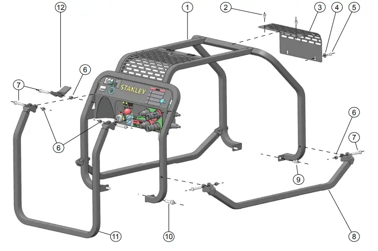
HP210 FRAME PARTS ILLUSTRATION
| ITEM # | PART # | QTY | DESCRIPTION |
| 1. | 76755 | 1 | Frame Weldment |
| 76712 | 1 | Frame Weldment (HP2510B05) | |
| 2. | 59074 | 2 | Flange Bolt |
| 3. | 59079 | 1 | Cooler Guard |
| 4. | 60945 | 2 | Washer |
| 5. | 15476 | 2 | Capscrew |
| 6. | 03906 | 7 | Nut |
| 7. | 370502 | 7 | Capscrew |
| 8. | 62268 | 2 | Lift Handle |
| 66064 | 2 | Lift Handle (HP2510B05) | |
| 9. | 23530 | 2 | Flange Bolt |
| 10. | 58976 | 2 | Flange Bolt |
| 11. | 62267 | 1 | Rear Lift Handle |
| 66063 | 1 | Rear Lift Handle (HP2510B05) | |
| 12. | 58916 | 1 | Handle Lock |
HP210 CONTROL PANEL PARTS ILLUSTRATION
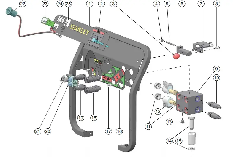
| ITEM # | PART # | QTY | DESCRIPTION |
| 1. | 74759 | 1 | Dash Decal |
| 2. | 62298 | 1 | Choke Cable Assembly |
| 3. | 204332 | 1 | Throttle Knob |
| 4. | 17134 | 1 | Nut |
| 5. | 76758 | 1 | Throttle Rod |
| 6. | 76757 | 1 | Throttle Stop |
| 7. | 208887 | 1 | Throttle Cable Assembly |
| 8. | 15476 | 2 | Capscrew |
| 9. | 79334 | 1 | Manifold |
| 10. | 59131 | 2 | Relief Valve |
| 11. | 62319 | 2 | Directional Valve and Cap |
| 12. | 60958 | 2 | Solenoid Coil |
| 13. | 08104 | 1 | Hollow Hex Plug |
| 14. | 60960 | 1 | Combiner Valve and Nut |
| 15. | 62320 | 1 | Solenoid Coil |
| 16. | 76759 | 1 | Dual Circuit Decal |
| 72783 | 1 | Dual Circuit Decal, Metric (HP210BBA) | |
| 17. | 60962 | 4 | Capscrew |
| 18. | 58856 | 2 | 3/8in. Female Coupler, -8 SAE |
| 19. | 58857 | 2 | 3/8in. Male Coupler, -8 SAE |
| 20. | 60956 | 2 | Rotary Switch |
| 21. | 67899 | 1 | 3 Position Rotary Switch |
| 22. | 64942 | 1 | 12V Receptacle Assembly |
| 23. | 60946 | 1 | Hour Meter |
| 24. | 28322 | 1 | CE Decal (HP210BBA, HP210BA) |
| 25. | 66653 | 1 | Sound Power Decal (HP210BBA, HP210BA) |
| 26. | 79312 | 1 | Wire Harness (see page 21) |
HP210 ENGINE PARTS LIST
FRONT
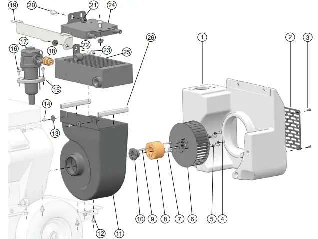
| ITEM # | PART # | QTY | DESCRIPTION |
| 1. | 59077 | 1 | Hydraulic Oil Tank |
| 2. | 59080 | 1 | Front Grille |
| 3. | 17821 | 4 | Capscrew |
| 4. | 80986 | 4 | Capscrew |
| 5. | 80984 | 4 | Lock Washer |
| 6. | 65107 | 1 | Blower Wheel |
| 7. | 00111 | 3 | Capscrew |
| 8. | 65108 | 1 | Blower Hub |
| 9. | 20990 | 1 | Key |
| 10. | 59076 | 1 | Bushing |
| 11. | 59083 | 1 | Blower Housing |
| 12. | 40433 | 5 | Flange Bolt |
| 13. | 26831 | 2 | Washer |
| 14. | 01213 | 2 | Capscrew |
| 15. | 64937 | 1 | Grip Plate |
| 16. | 43687 | 2 | Capscrew |
| 17. | 40080 | 1 | Filter Assembly |
| 18. | 51292 | 1 | Standard Thread Union |
| 19. | 66215 | 1 | Cooler Mount (HP210BY) |
| 20. | 59074 | 2 | Flange Bolt (HP210BY) |
| 21. | 59095 | 3 | Flange Nut (HP210BY) |
| 22. | 60774 | 1 | Hose Clamp (HP210BY) |
| 23. | 59075 | 1 | Flange Bolt (HP210BY) |
| 24. | – | – | Provided with Engine (HP210BY) |
| 25. | 59091 | 1 | Cooler |
| 26. | 62296 | 2 | Weather Strip |
BACK
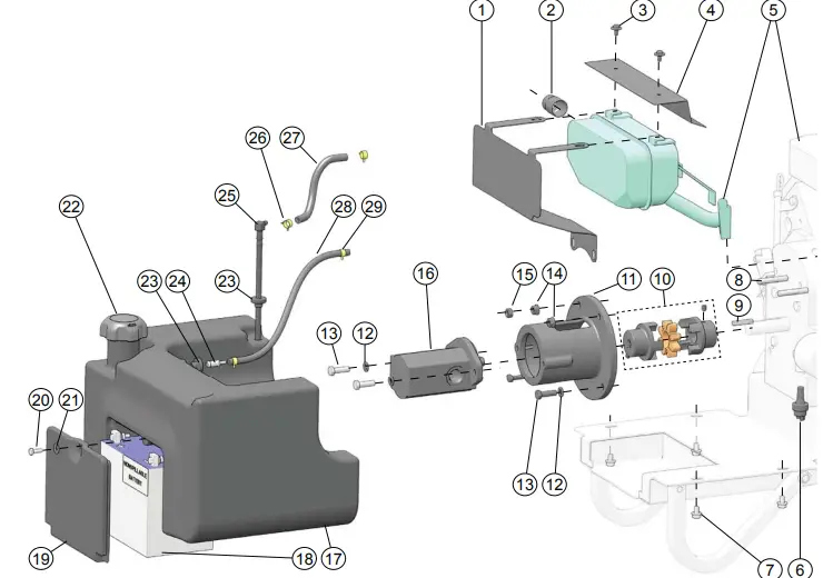
| ITEM # | PART # | QTY | DESCRIPTION |
| 1. | 62324 | 1 | Heat Shield |
| 66214 | 1 | Heat Shield (HP210BY) | |
| 2. | 65456 | 1 | Spark Arrester (HP210BA, HP210BBA) |
| 3. | 36152 | 2 | Screw |
| 4. | 36151 | 1 | Heat Shield |
| 5. | 76753 | 1 | Engine with Muffler |
| 76721 | 1 | Engine(HP210BY) | |
| 6. | 31765 | 1 | Pressure Switch |
| 7. | 40433 | 4 | Flange Bolt |
| 8. | 62385 | 2 | Stud |
| 9. | 07819 | 1 | Square Key |
| 10. | 56656 | 1 | Coupling |
| 11. | 56655 | 1 | Pump Mount |
| 12. | 01459 | 4 | Washer |
| 13. | 07860 | 4 | Capscrew |
| ITEM # | PART # | QTY | DESCRIPTION |
| 14. | 18893 | 2 | Flange Nut |
| 15. | 371503 | 1 | Nut |
| 16. | 27695 | 1 | Pump |
| 17. | 73050 | 1 | Fuel Tank |
| 18. | 04303 | 1 | Battery |
| 19. | 60912 | 1 | Battery Cover |
| 20. | 15476 | 1 | Capscrew |
| 21. | 60945 | 1 | Washer |
| 22. | 71794 | 1 | Fuel Cap |
| 23. | 60920 | 2 | Grommet |
| 24. | 72401 | 1 | Grommet Connector |
| 25. | 60919 | 1 | Fuel Elbow |
| 26. | 72317 | 2 | Hose Clamp |
| 27. | 62289 | 1 | Fuel Hose |
| 28. | 72571 | 1 | Fuel Vapor Hose |
| 29. | 72451 | 2 | Hose Clamp |
HP210 ENGINE PARTS LIST – BASE
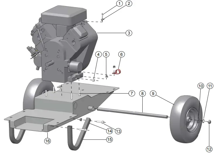
| ITEM # | PART # | QTY | DESCRIPTION |
| 1. | 64991 | 1 | Capscrew |
| 2. | 56709 | 1 | Cable Clamp |
| 3. | 76753 | 1 | Engine |
| 76721 | 1 | Engine (HP210BY) | |
| 4. | 01212 | 1 | Pipe Plug |
| 5. | 12787 | 4 | Flange Nut |
| 6. | 24287 | 1 | Hose Clamp |
| 7. | 58942 | 4 | Flange Bolt |
| 8. | 58917 | 1 | Axle |
| 9. | 56633 | 2 | Foam Filled Tires |
| 10. | 21318 | 2 | Washer |
| 11. | 31240 | 2 | Retaining Ring |
| 12. | 21714 | 2 | Handle Bumper |
| 13. | 58976 | 4 | Flange Bolt |
| 14. | 18893 | 2 | Flange Nut |
| 15. | 58975 | 2 | Foot |
| 16. | 58897 | 1 | Frame Base Weldment |
HOSES, FITTINGS & CLAMPS
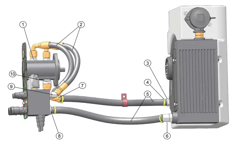
| ITEM # | PART # | QTY | DESCRIPTION |
| 1. | 350104 | 2 | Connector |
| 2. | 58943 | 2 | Hose |
| 3. | 59105 | 1 | Hose Barb |
| 4. | 62199 | 4 | Hose Clamp |
| 5. | 59089 | 2 | Hose |
| 6. | 40364 | 1 | Elbow |
| 7. | 58569 | 1 | Elbow |
| 8. | 59104 | 1 | Hose Barb |
| 9. | 350000 | 4 | Elbow |
| 10. | 02773 | 1 | Adapter |
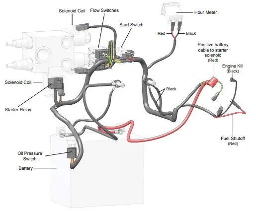
MAIN WIRING HARNESS
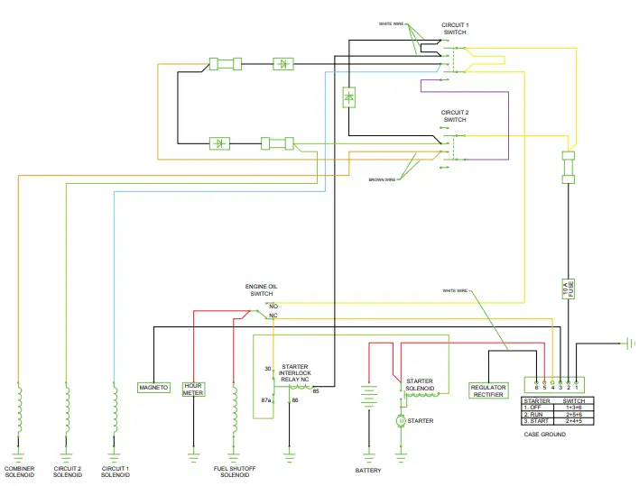
ELECTRICAL SCHEMATIC
DECLARATION OF CONFORMITY
DECLARATION OF CONFORMITY
I, the undersigned: Nuerenberg, David ,Surname and First names
hereby declare that the equipment specified hereunder:
- Category: Hydraulic Power Unit
- Make: Stanley
- Type: GTR20B01 Auto Throttle (HP210BA Manual Throttle)
- Serial number of equipment:: All
Has been manufactured in conformity with
| Directive/Standards | No | Approved body |
| EN ISO | 12100:2010 | Self |
Special Provisions: None
Measurements: Measured Sound Power Level 99 LwA
Representative in the Union: Patrick Vervier, Stanley Dubuis 17-19 ue Jules Berthonneau-BP 3406 41034 Blois Cedex, France.
Done at: Stanley Hydraulic Tools, Milwaukie, Oregon USA Date/ 7-21-2016
Signature:
Position: 
Stanley Infrastructure
3810 SE Naef Road
Milwaukie, Oregon 97267-5698 USA
(503) 659-5660 / Fax (503) 652-1780
www.stanleyinfrastructure.com