CITY THEATRICAL QolorFLEX 4x5A DINrail RJ45 Dimmer User Guide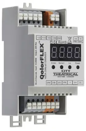
FEATURES & COMPONENT IDENTIFICATION
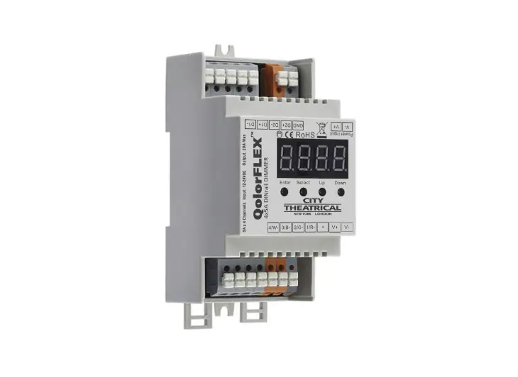
The Qolor FLEX 4x5A DIN rail RJ45 Dimmer can control a full 20A of LED tape spread over four channels of 5A each. It uses constant voltage technology which ensures consistent full range dimming that is especially important at low end light levels. The unit mounts to a standard hat section DIN rail, and features two RJ45 connectors for DMX communication.
An easy to read onboard display and four button user interface allow selection of Modes, DMX addresses, setting quantity of DMX channels, selecting 8 or 16 bit output resolution, setting PWM frequency (500Hz to 30KHz), setting output dimming curve values for
matching the dimming curves of other dimmers in use, and setting the device’s operating profile. The Qolor FLEX 4x5A DIN rail RJ45 Dimmer is also RDM capable. Both DMX and Standalone Modes are available depending on your application. The unit requires a separate power supply providing input voltage of 12-24VDC. The maximum current load per channel is 5A with a maximum device output of 20A.
The Qolor FLEX 4x5A DINrail RJ45 Dimmer operates perfectly with City Theatrical’s Qolor FLEX LED tape, the LED tape of professionals on Broadway, network television, and architectural lighting installations.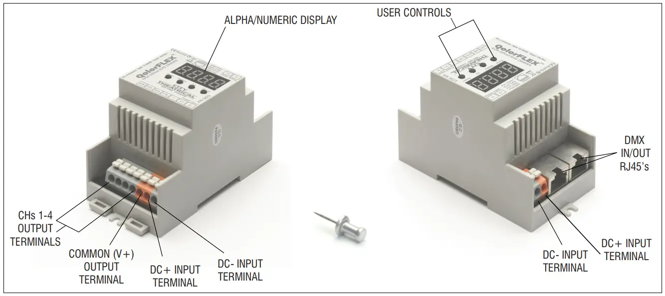
Mode: Sets the Mode to either DMX (Run 1) or Standalone (Run 2)
Quick Start Instructions:
- Connect the Qolor FLEX 4x5A DIN rail RJ45 Dimmer to your DMX controller using a cable connected to either of the RJ45 DMX input/output connectors. Connect the DMX out cable to the other RJ45 connector as needed.
- Connect your load to the output channel spring terminals. For single color LED tape with two connection wires, connect the V- (black) wire to any one of the four output channel terminals and the V+ (red) wire to its corresponding terminal. When using multi-color LED Tape, connect as follows: CH1-red, CH2-green, CH3-blue, and CH4-fourth color. Note-The V+ (common) circuit for multicolor tape will be connected to either a black or white wire. To determine which is correct, look at one of the sets of contacts on the tape itself and note which color wire is connected to the one labeled (+). Do not exceed the maximum load capacity of 5A per channel.
- Connect the appropriate power supply providing 12-24VDC to the power input spring terminals. Note-The size of the power supply must match the tape being used in both voltage and watts. Qolor FLEX™ 4x5A DIN rail RJ45 Dimmer’s maximum output power rating is: 240W (12V), and 480W(24V).
Control Interface
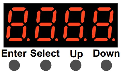
Operation
- Press “Up” to scroll thru menu choices
- Press “Select” to enable programming- (display flashes)
- Use “Up” or “Down” buttons to set values
- Press “Enter” to save value.
Note: To restore factory defaults, press and hold both “Enter” and “Select” for five seconds until display goes out.
DMX Address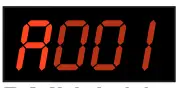 | PWM Frequency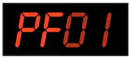 |
DMX Channel Qty | Dimming Curve Value |
Output Resolution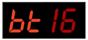 | Operating Profile |
| DMX Start Address: (Factory default is 001) Sets the DMX address for the dimmer. |
| DMX Channel Qty: (Factory default is 05) SETTINGS:
|
| Output Resolution: (Factory default is 16) Resolution determines the smoothness of the dimming. 8 bit uses 1 DMX channel, while 16 bit uses 2. AVAILABLE SETTINGS: 08 or 16 |
| PWM Frequency: (Factory default is 05) PWM frequency is used to tune the dimmer for flicker free operation when used with high speed cameras. A high PWM value produces the least amount of flicker. A low PWM value produces better dimming quality. Always perform a camera test to confirm optimal results. AVAILABLE SETTINGS: 00 thru 30 |
| To Set for Stand Alone: Set to Stand Alone Mode by pushing “Up” button until “run1” is shown. “run1” denotes DMX mode. Hit “Enter” button, and “Up” button to select “run2”, which denotes Stand Alone Mode. Cycle power to unit. In Stand Alone Mode:
To change back to DMX Mode, select “run1” and cycle power |
| Dimming Curve: (Factory default is 1.5 ) The Dimming Curve may be adjusted to affect the rate of rise and fall of the dimmer. Values less than 1.0 increase the rate, while values greater than 1.0 decrease the rate. (1.0 is linear). 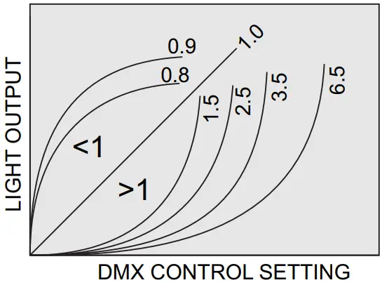 AVAILABLE SETTINGS: 0.1 thru 9.9 |
Device DMX Profiles (Factory default is 1.1)
| DMX Address is 001,CH01 dp1.1 | dp2.1 | |
| Channel 1 | For all output dimming | For all output dimming |
| Channel 2 | For all output Fine dimming | |
| DMX Address is 001,CH02 dp1.1 | dp2.1 | dp3.2 | |
| Channel 1 | For output 1,3 dimming | For output 1,3 dimming | For output 1,3 dimming |
| Channel 2 | For output 2,4 dimming | For output 1,3 Fine dimming | For output 2,4 dimming |
| Channel 3 | For output 2,4 dimming | For all output dimming | |
| Channel 4 | For output 2,4 Fine dimming | ||
| DMX Address is 001,CH03 dp1.1 | dp2.1 | dp4.3 | dp5.3 | |
| Channel 1 | For output 1 dimming | For output 1 dimming | For output 1 dimming | For output 1 dimming |
| Channel 2 | For output 2 dimming | For output 1 Fine dimming | For output 2 dimming | For output 2 dimming |
| Channel 3 | For output 3,4 dimming | For output 2 dimming | For output 3,4 dimming | For output 3,4 dimming |
| Channel 4 | For output 2 Fine dimming | For all output dimming | For all output dimming | |
| Channel 5 | For output 3,4 dimming | For all output dimming | Strobe Effects | |
| Channel 6 | For output 3,4 Fine dimming | |||
| DMX Address is 001,CH04 dp1.1 | dp2.1 | dp5.4 | dp6.4 | |
| Channel 1 | For output 1 dimming | For output 1 dimming | For output 1 dimming | For output 1 dimming |
| Channel 2 | For output 2 dimming | For output 1 Fine dimming | For output 2 dimming | For output 2 dimming |
| Channel 3 | For output 3 dimming | For output 2 dimming | For output 3 dimming | For output 3 dimming |
| Channel 4 | For output 4 dimming | For output 2 Fine dimming | For output 4 dimming | For output 4 dimming |
| Channel 5 | For output 3 dimming | For all output dimming | For all output dimming | |
| Channel 6 | For output 3 Fine dimming | Strobe Effects | ||
| Channel 7 | For output 4 dimming | |||
| Channel 8 | For output 4 Fine dimming | |||
Should the dimmer experience an input voltage issue or output overload the display will flash repeatedly.
Once the issue is corrected, power cycle to reset the unit.
Customer Support
475 BARELL AVE, CARLSTADT, NJ 07072
800/230/9497 201/549/1160 201/549/1161 FAX
www.citytheatrical.com


 User Guide")


 Mini Dimmer Goaezmnhhd1 Manual")


