![]() NexAIoT Co., Ltd.
NexAIoT Co., Ltd.
IoT Automation Solutions Business Group
Fan-less Computer
NISE 109
User Manual
PREFACE
Copyright
This publication, including all photographs, illustrations and software, is protected under international copyright laws, with all rights reserved. No part of this manual may be reproduced, copied, translated or transmitted in any form or by any means without the prior written consent from NexAIoT Co., Ltd.
Disclaimer
The information in this document is subject to change without prior notice and does not represent commitment from NexAIoT Co., Ltd. However, users may update their knowledge of any product in use by constantly checking its manual posted on our website: http://www.nexaiot.com. NexAIoT shall not be liable for direct, indirect, special, incidental, or consequential damages arising out of the use of any product, nor for any infringements upon the rights of third parties,which may result from such use. Any implied warranties of merchantability or fitness for any particular purpose is also disclaimed.
Acknowledgements
NISE 109 is a trademark of NexAIoT Co., Ltd. All other product names mentioned herein are registered trademarks of their respective owners.
Regulatory Compliance Statements
This section provides the FCC compliance statement for Class A devices and describes how to keep the system CE compliant.
Declaration of Conformity
FCC
This equipment has been tested and verified to comply with the limits for a Class A digital device, pursuant to Part 15 of FCC Rules. These limits are designed to provide reasonable protection against harmful interference when the equipment is operated in a commercial environment. This equipment generates, uses, and can radiate radio frequency energy and, if not installed and used in accordance with the instructions, may cause harmful interference to radio communications. Operation of this equipment in a residential area (domestic environment) is likely to cause harmful interference, in which case the user will be required to correct the interference (take adequate measures) at their own expense.
CE
The product(s) described in this manual complies with all applicable European Union (CE) directives if it has a CE marking. For computer systems to remain CE compliant, only CE-compliant parts may be used. Maintaining CE compliance also requires proper cable and cabling techniques.
RoHS Compliance![]() NexAIoT RoHS Environmental Policy and Status Update
NexAIoT RoHS Environmental Policy and Status Update
NexAIoT is a global citizen for building the digital infrastructure. We are committed to providing green products and services, which are compliant with European Union RoHS (Restriction on Use of Hazardous Substance in Electronic Equipment) directive 2011/65/EU, to be your trusted green partner and to protect our environment.
RoHS restricts the use of Lead (Pb) < 0.1% or 1,000ppm, Mercury (Hg) < 0.1% or 1,000ppm, Cadmium (Cd) < 0.01% or 100ppm, Hexavalent Chromium (Cr6+) < 0.1% or 1,000ppm, Polybrominated biphenyls (PBB) < 0.1% or 1,000ppm, and Polybrominated diphenyl Ethers (PBDE) < 0.1% or 1,000ppm.
In order to meet the RoHS compliant directives, NexAIoT has established an engineering and manufacturing task force to implement the introduction of green products. The task force will ensure that we follow the standard NexAIoT development procedure and that all the new RoHS components and new manufacturing processes maintain the highest industry quality levels for which NexAIoT are renowned.
The model selection criteria will be based on market demand. Vendors and suppliers will ensure that all designed components will be RoHS compliant.
How to recognize NexAIoT RoHS Products?
For existing products where there are non-RoHS and RoHS versions, the suffix “(LF)” will be added to the compliant product name.
All new product models launched after January 2013 will be RoHS compliant.
They will use the usual NexAIoT naming convention.
Warranty and RMA
NexAIoT Warranty Period
NexAIoT manufactures products that are new or equivalent to new in accordance with industry standard. NexAIoT warrants that products will be free from defect in material and workmanship for 2 years, beginning on the date of invoice by NexAIoT.
NexAIoT Return Merchandise Authorization (RMA)
- Customers shall enclose the “NexAIoT RMA Service Form” with the returned packages.
- Customers must collect all the information about the problems encountered and note anything abnormal or, print out any on-screen messages, and describe the problems on the “NexAIoT RMA Service Form” for the RMA number apply process.
- Customers can send back the faulty products with or without accessories (manuals, cable, etc.) and any components from the card, such as CPU and RAM. If the components were suspected as part of the problems, please note clearly which components are included. Otherwise, NexAIoT is not responsible for the devices/parts.
- Customers are responsible for the safe packaging of defective products, making sure it is durable enough to be resistant against further damage and deterioration during transportation. In case of damages occurred during transportation, the repair is treated as “Out of Warranty.”
- Any products returned by NexAIoT to other locations besides the customers’ site will bear an extra charge and will be billed to the customer.
Repair Service Charges for Out-of-Warranty Products
NexAIoT will charge for out-of-warranty products in two categories, one is basic diagnostic fee and another is component (product) fee.
System Level
- Component fee: NexAIoT will only charge for main components such as SMD chip, BGA chip, etc. Passive components will be repaired for free, ex: resistor, capacitor.
- Items will be replaced with NexAIoT products if the original one cannot be repaired. Ex: motherboard, power supply, etc.
- Replace with 3rd party products if needed.
- If RMA goods can not be repaired, NexAIoT will return it to the customer without any charge.
Board Level
- Component fee: NexAIoT will only charge for main components, such as SMD chip, BGA chip, etc. Passive components will be repaired for free, ex: resistors, capacitors.
- If RMA goods can not be repaired, NexAIoT will return it to the customer without any charge.
Warnings
Read and adhere to all warnings, cautions, and notices in this guide and the documentation supplied with the chassis, power supply, and accessory modules. If the instructions for the chassis and power supply are inconsistent with these instructions or the instructions for accessory modules, contact the supplier to find out how you can ensure that your computer meets safety and regulatory requirements.
Cautions
Electrostatic discharge (ESD) can damage system components. Do the described procedures only at an ESD workstation. If no such station is available, you can provide some ESD protection by wearing an antistatic wrist strap and attaching it to a metal part of the computer chassis.
Installation Recommendations
Ensure you have a stable, clean working environment. Dust and dirt can get into components and cause a malfunction. Use containers to keep small components separated. Adequate lighting and proper tools can prevent you from accidentally damaging the internal components. Most of the procedures that follow require only a few simple tools, including the following:
- A Philips screwdriver
- A flat-tipped screwdriver
- A grounding strap
- An anti-static pad
Using your fingers can disconnect most of the connections. It is recommended that you do not use needle-nose pliers to disconnect connections as these can damage the soft metal or plastic parts of the connectors.
Safety Information
Before installing and using the device, note the following precautions:
- Read all instructions carefully.
- Do not place the unit on an unstable surface, cart, or stand.
- Follow all warnings and cautions in this manual.
- When replacing parts, ensure that your service technician uses parts specified by the manufacturer.
- Avoid using the system near water, in direct sunlight, or near a heating device.
- The load of the system unit does not solely rely for support from the rackmounts located on the sides. Firm support from the bottom is highly necessary in order to provide balance stability.
- The computer is provided with a battery-powered real-time clock circuit. There is a danger of explosion if battery is incorrectly replaced. Replace only with the same or equivalent type recommended by the manufacturer. Discard used batteries according to the manufacturer’s instructions.
- This product is intended to be supplied by an approved power adapter, rated 12Vdc, 5A or 24Vdc, 2.5A minimum and Tma 55 degree Celsius. If further assistance is needed, please contact NexAIoT for further information.
![]() Danger of explosion if battery is incorrectly replaced. Replace with the same or equivalent type recommended by the manufacturer. Discard used batteries according to the manufacturer’s instructions.
Danger of explosion if battery is incorrectly replaced. Replace with the same or equivalent type recommended by the manufacturer. Discard used batteries according to the manufacturer’s instructions.
ATTENTION![]() bghjytyjuyukyuyuyuIL Y A RISQUE D’EXPLOSION SI LA BATTERIE EST REMPLACÉE PAR UNE BATTERIE DE TYPE INCORRECT. METTRE AU REBUT LES BATTERIES USAGÉES CONFORMÉMENT AUX INSTRUCTIONS.
bghjytyjuyukyuyuyuIL Y A RISQUE D’EXPLOSION SI LA BATTERIE EST REMPLACÉE PAR UNE BATTERIE DE TYPE INCORRECT. METTRE AU REBUT LES BATTERIES USAGÉES CONFORMÉMENT AUX INSTRUCTIONS.
Safety Precautions
- Read these safety instructions carefully.
- Keep this User Manual for later reference.
- Disconnect this equipment from any AC outlet before cleaning. Use a damp cloth. Do not use liquid or spray detergents for cleaning.
- For plug-in equipment, the power outlet socket must be located near the equipment and must be easily accessible.
- Keep this equipment away from humidity.
- Put this equipment on a stable surface during installation. Dropping it or letting it fall may cause damage.
- The openings on the enclosure are for air convection to protect the equipment from overheating. DO NOT COVER THE OPENINGS.
- Make sure the voltage of the power source is correct before connecting the equipment to the power outlet.
- Place the power cord in a way so that people will not step on it. Do not place anything on top of the power cord. Use a power cord that has been approved for use with the product and that it matches the voltage and current marked on the product’s electrical range label. The voltage and current rating of the cord must be greater than the voltage and current rating marked on the product.
- All cautions and warnings on the equipment should be noted.
- If the equipment is not used for a long time, disconnect it from the power source to avoid damage by transient overvoltage.
- Never pour any liquid into an opening. This may cause fire or electrical shock.
- This equipment is not suitable for use in locations where children are likely to be present.
- Ensure to connect the power cord to a socket-outlet with earthing connection.
- Never open the equipment. For safety reasons, the equipment should be opened only by qualified service personnel.
- If one of the following situations arises, get the equipment checked by service personnel:
a. The power cord or plug is damaged.
b. Liquid has penetrated into the equipment.
c. The equipment has been exposed to moisture.
d. The equipment does not work well, or you cannot get it to work according to the user’s manual.
e. The equipment has been dropped and damaged.
f. The equipment has obvious signs of breakage. - Do not place heavy objects on the equipment.
- The unit uses a three-wire ground cable which is equipped with a third pin to ground the unit and prevent electric shock. Do not defeat the purpose of this pin. If your outlet does not support this kind of plug, contact your electrician to replace your obsolete outlet.
- CAUTION: DANGER OF EXPLOSION IF BATTERY IS INCORRECTLY REPLACED. REPLACE ONLY WITH THE SAME OR EQUIVALENT TYPE RECOMMENDED BY THE MANUFACTURER. DISCARD USED BATTERIES ACCORDING TO THE MANUFACTURER’S INSTRUCTIONS.
Technical Support and Assistance
- For the most updated information of NexAIoT products, visit NexAIoT’s website at www.nexaiot.com.
- For technical issues that require contacting our technical support team or sales representative, please have the following information ready before calling:
– Product name and serial number
– Detailed information of the peripheral devices
– Detailed information of the installed software (operating system, version, application software, etc.)
– A complete description of the problem
– The exact wordings of the error messages
Warning!
- Handling the unit: carry the unit with both hands and handle it with care.
- Maintenance: to keep the unit clean, use only approved cleaning products or clean with a dry cloth.
Conventions Used in this Manual![]() Warning:
Warning:
Information about certain situations, which if not observed, can cause personal injury. This will prevent injury to yourself when performing a task.![]() Caution:
Caution:
Information to avoid damaging components or losing data.![]() Note:
Note:
Provides additional information to complete a task easily.
Global Service Contact Information
| Headquarters NEXCOM International Co., Ltd. 9F, No. 920, Chung-Cheng Rd., Zhonghe District, New Taipei City, 23586, Taiwan, R.O.C. Tel: +886-2-8226-7786 Fax: +886-2-8226-7782 www.nexcom.com | NexCOBOT Taiwan Co., Ltd. 13F, No.916, Chung-Cheng Rd., Zhonghe District, New Taipei City, 23586, Taiwan, R.O.C. Tel: +886-2-8226-7786 Fax: +886-2-8226-7926 Email: [email protected] www.nexcobot.com | TMR Technology Corp. 13F, No.916, Chung-Cheng Rd., Zhonghe District, New Taipei City, 23586, Taiwan, R.O.C. Tel: +886-2-8226-7786 Fax: +886-2-8226-7782 Email: [email protected] www.nexcom.com.tw |
| Asia Taiwan NexAIoT Headquarters Industry 4.0 and Cloud Services 13F, No.916, Zhongzheng Rd., Zhonghe District, New Taipei City, 23586, Taiwan, R.O.C. Tel: +886-2-8226-7796 Fax: +886-2-8226-7926 Email: [email protected] www.nexaiot.com | GreenBase Technology Corp. 13F, No.922, Chung-Cheng Rd., Zhonghe District, New Taipei City, 23586, Taiwan, R.O.C. Tel: +886-2-8226-7786 Fax: +886-2-8226-7900 Email: [email protected] www.nexcom.com.tw | China NEXSEC Incorporated 5F, No.4, No.7 Fengxian Middle Rd., (Beike Industrial Park), Haidian District, Beijing, 100094, China Tel: +86-10-5704-2680 Fax: +86-10-5704-2681 Email: [email protected] www.nexsec.cn |
| NexAIoT Co., Ltd. Taichung Office 16F, No.250, Sec. 2, Chongde Rd., Beitun District, Taichung City, 406, Taiwan, R.O.C. Tel: +886-4-2249-1179 Fax: +886-4-2249-1172 Email: [email protected] www.nexaiot.com | EMBUX Technology Co., Ltd. 13F, No.916, Chung-Cheng Rd., Zhonghe District, New Taipei City, 23586, Taiwan, R.O.C. Tel: +886-2-8226-7786 Fax: +886-2-8226-7782 Email: [email protected] www.nexcom.com.tw | NEXCOM Shanghai No.4, 16 Building, Shanghai OMNI Tech & Science Park No. 1699, Douhui Rd., Shanghai, 201108, China Tel: +86-21-5278-5868 Fax: +86-21-3251-6358 Email: [email protected] www.nexcom.cn |
| NEXCOM Surveillance Technology Corp. 5F, Building C, ZhenHan Industrial Zone, GanKeng Community, Buji Street, LongGang District, ShenZhen, 518112, China Tel: +86-755-8364-7768 Fax: +86-755-8364-7738 Email: [email protected] www.nexcom.cn | NexCOBOT China Room 501, Building 1, Haichuang Building, No.7 Qingyi Road, Guicheng Street, Nanhai District, Foshan City, Guangdong Province, 528314, China Tel: +86-757-8625-7118 Email: [email protected] www.nexcobot.com.cn | America USA NEXCOM USA 46665 Fremont Blvd., Fremont CA 94538, USA Tel: +1-510-656-2248 Fax: +1-510-656-2158 Email: [email protected] www.nexcomusa.com |
| NEXCOM United System Service Room 603/604, Huiyinmingzun Plaza Bldg. 1, No. 609, Yunlin East Rd., Shanghai, 200062, China Tel: +86-21-5278-5868 Fax: +86-21-3251-6358 Email: [email protected] www.nexcom.cn | Beijing NexGemo Technology Co.,Ltd. 5F, Gemotech Building, No.1, Development Rd., Changping International Information Industry Base, Changping District, Beijing, 102206, China Tel: +86-10-8190-9328 Fax: +86-10-8190-9456 Email: [email protected] www.nexgemo.cn | Europe United Kingdom NEXCOM EUROPE 10 Vincent Avenue, Crownhill Business Centre, Milton Keynes, Buckinghamshire MK8 0AB, United Kingdom Tel: +44-1908-267121 Fax: +44-1908-262042 Email: [email protected] www.nexcom.co.uk |
| NEXGOL Chongqing 1F, Building B4, Electronic 2nd Area, (Phoenix Lake Industrial Park), Yongchuan Dist., Chongqing City, 402160, China Tel: +86-23-4960-9080 Fax: +86-23-4966-5855 Email: [email protected] www.nexcobot.com/NexGOL | Japan NEXCOM Japan 9F, Tamachi Hara Bldg., 4-11-5, Shiba Minato-ku, Tokyo, 108-0014, Japan Tel: +81-3-5419-7830 Fax: +81-3-5419-7832 Email: [email protected] www.nexcom-jp.com |
Package Contents
Before continuing, verify that the package that you received is complete.
Your NISE 109 package should have all the items listed in the following table.
| Item | Part Number | Description | Qty |
| 1 | 4NCPM00302X00 | (T)Terminal Blocks 3P Phoenix Contact:1777992 5.08mm MALE DIP GREEN | 1 |
| 2 | 4NCPM00203X00 | Terminal Blocks 2P Phoenix Contact:1803578 3.81mm MALE ASSY GREEN | 1 |
| 3 | 5050900008X00 | Mini PCI-e Bracket Ver:A MP 30x29x2.1mm SPCC T=1.0mm | 1 |
| 4 | 5060900226X00 | Mini PCI-e Bracket CHYUAN-JYH 29x30x2.1mm SPCC T=1.0mm NI | 1 |
| 5 | 5061600245X00 | Washer Kangyang:TW-320-01 10.4×6.4mm T=1mm NYLON BLACK | 4 |
| 6 | 5060200437X00 | Thermal Pad E-Lin 30x20x12mm PK404SHC With Back Glue | 2 |
| 7 | 50311F0144X00 | I Head Screw Long Fei: M3x4mm NI NYLOK | 5 |
| 8 | 50311F0295X00 | Flat Head Screw Long Fei:F2x4 NYLOK NIGP F2x4 NIGP NYLOK | 1 |
| 9 | 50311F0330X00 | Round Head Screw Long Fei:P2x3 ISO+NYLON P2x3 NI NYLOK | 2 |
| 10 | 50311P0014X00 | P Head Screw Kang Yang:M3-5 5.5×2.1x5mm PLASTICS | 4 |
Ordering Information
The following information below provides ordering information for NISE 109.
NISE 109-E01 system (P/N: 10J00010900X0)
- Intel® Atom® processor x6211E 1.3Ghz
NISE 109-E02 system (P/N: 10J00010901X0)
- Intel® Celeron® processor J6412 2.0Ghz
- 24V, 60W AC to DC power adapter w/o power cord (P/N: 7400060054X00)
- 24V, 120W AC /DC power adapter w/o power cord (P/N: 7400120029X00)
CHAPTER 1: Product Introduction
Overview
Key Features
- Onboard Intel Processor x6211E 1.3Ghz® Celeron® 630SE Processor J6412 2.0Ghz or Atom®
- Dual display port: 1 x HDMI & 1 x DP
- 2 x Intel I210-IT GbE LAN ports; support WoL, teaming, PXE and Ethercat®
- 3 x USB3.0 & 3 x USB2.0
- 2 x RS232 & 2 x RS232/422/485
- Support 1 x 2.5” SSD & 1 x M.2 Key B storage
- Support 9~30V DC input; support ATX power mode
- Operation temperature
– Intel® J6412: -5~55°C
– Intel Atom® Celeron® x6211E: -20~70°C - Support 1 x M.2 & 1 x mini-PCIe expansion slot
Hardware Specifications
CPU Support
- Onboard Intel processor J6412 2.0Ghz® Celeron®
- Onboard Intel Atom® processor x6211E 1.3 Ghz
Main Memory
- 1 x SO-DIMM DDR4 non ECC up to 2666 MT/s, 16G max., support IBECC, non-ECC, and un-buffered memory
Display Option
- 1 x DP 1.4
- 1 x HDMI 1.4
I/O Interface – Front
- ATX power on/off switch
- Status LEDs: storage, battery, and COM1/2 TX/RX.
- 3 x USB 3.0 (900mA per each)
- 1 x USB 2.0 (500mA per each)
- 2 x Intel® I210-IT GbE LAN ports; support WoL, teaming and PXE
- 1 x DP
- 1 x HDMI
- 1 x DB9 for COM3, it supports RS232/422/485 with auto flow control
– Jumper-free setting on RS232/422/485 by BIOS - 1 x Line-out and 1 x Mic-in
- 1 x Optional I/F window
- 3-pin DC input, support 9~30V DC
I/O Interface – Rear
- 3 x DB9 for COM2, COM3 & COM4
– COM2: RS232/422/485 auto flow control
– COM3 & COM4: RS232 - 2 x USB 2.0 (500mA per each)
- 1 x 2-pin remote power on/off switch
- 2 x Antenna hole for optional Wi-Fi/4G/LTE antenna
Storage Device
- 1 x M.2 (SATA/PCIe x 1, 2242, Key B & B+M)
- 1 x 2.5“ SATAIII SSD
Expansion Slot
- 1 x mini-PCIe socket for optional Wi-Fi/3.5G/4G/LTE module (for 3.5G/4G/LTE function, support SIM card holder onboard)
Power Requirements
- Power input: +9 to +30V DC
- 1 x Optional 24V, 60W power adapter
Supported OS
- Windows 10 64-bit
- Linux Kernel
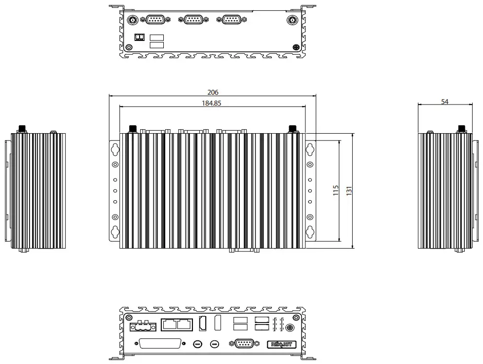
Dimensions
- 185mm (W) x 131mm (D) x 54mm (H) without wall mount bracket
Construction
- Aluminum and metal chassis with fanless design
Environment
- Operating temperature (according to IEC60068-2-1, IEC60068-2-2, IEC60068-2-14):
– NISE 109-E01 ambient with air flow: -20°C to 70°C
– NISE 109-E02 ambient with air flow: -5°C to 55°C - Storage temperature: -20°C to 80°C
- Relative humidity: 10% to 90% (non-condensing)
- Shock protection:
– HDD: 20G, half sine, 11ms, IEC60068-2-27
– M.2: 50G, half sine, 11ms, IEC60068-2-27 - Vibration protection with SSD & M.2 condition:
– Random: 2Grms @ 5~500 Hz, IEC60068-2-64
– Sinusoidal: 2Grms @ 5~500 Hz, IEC60068-2-6
Certifications
- CE approval
– EN61000-6-2
– EN61000-6-4 - FCC Class A
OS Support
- Linux Kernel version 4.1
- Windows 10 IoT Enterprise, 64-bit
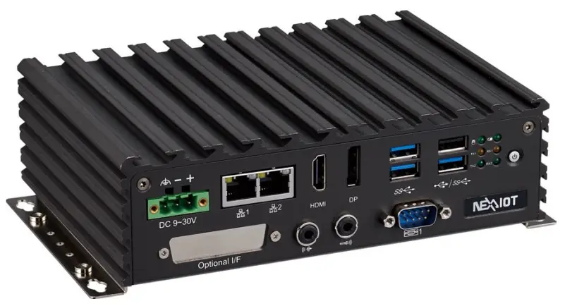
Knowing Your NISE 109 Front Panel
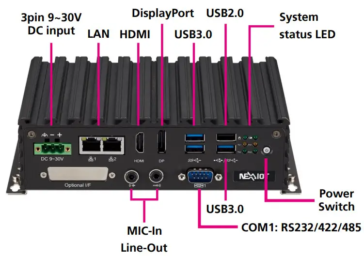
Power Switch
Press to power-on or power-off the system.
System status LED
Indicates the power status, RTC battery status, storage activity, serial port send (Tx), and transmit (Rx) activity of the system.
USB 2.0
USB 2.0 ports to connect the system with USB 2.0/1.1 devices.
USB 3.0
USB 3.0 ports to connect the system with USB 3.0/2.0 devices.
DisplayPort
A DisplayPort port used to connect DisplayPort interface displays.
HDMI
A HDMI port used to connect HDMI interface displays.
LAN
Two RJ45 ports used to connect the system to a local area network.
DC Input
Used to plug a DC power cord.
COM
– COM1: RS232/422/485 with auto flow control
Mic-In/Line-Out
Mic-In: Used to connect an external microphone
Line-Out: Used to connect a headphone or a speaker.
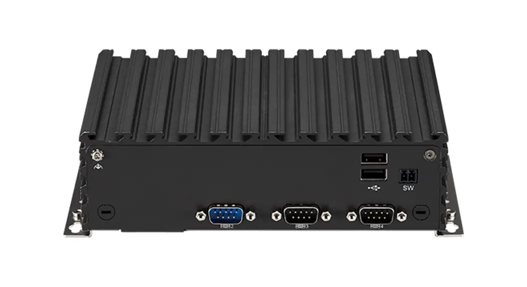
Rear Panel
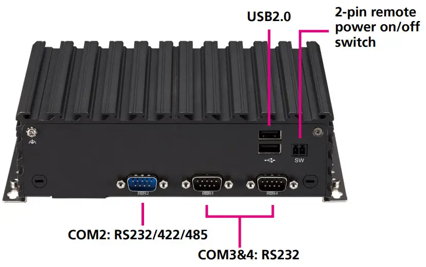
Remote On/Off Switch
Used to connect a remote to power on/off the system.
USB 2.0
USB 2.0 ports to connect the system with USB 2.0/1.1 devices.
COM
– COM2: RS232/422/485 with auto flow control
– COM3&4: RS232
Mechanical Dimensions
CHAPTER 2: Jumpers and Connectors
This chapter describes how to set the jumpers and connectors on the NISE 109 motherboard.
Before You Begin
- Ensure you have a stable, clean working environment. Dust and dirt can get into components and cause a malfunction. Use containers to keep small components separated.
- Adequate lighting and proper tools can prevent you from accidentally damaging the internal components. Most of the procedures that follow require only a few simple tools, including the following:
– A Philips screwdriver
– A flat-tipped screwdriver
– A set of jewelers screwdrivers
– A grounding strap
– An anti-static pad - Using your fingers can disconnect most of the connections. It is recommended that you do not use needle-nosed pliers to disconnect connections as these can damage the soft metal or plastic parts of the connectors.
- Before working on internal components, make sure that the power is off. Ground yourself before touching any internal components, by touching a metal object. Static electricity can damage many of the electronic components. Humid environments tend to have less static electricity than dry environments. A grounding strap is warranted whenever danger of static electricity exists.
Precautions
Computer components and electronic circuit boards can be damaged by discharges of static electricity. Working on computers that are still connected to a power supply can be extremely dangerous.
Follow the guidelines below to avoid damage to your computer or yourself:
- Always disconnect the unit from the power outlet whenever you are working inside the case.
- If possible, wear a grounded wrist strap when you are working inside the computer case. Alternatively, discharge any static electricity by touching the bare metal chassis of the unit case, or the bare metal body of any other grounded appliance.
- Hold electronic circuit boards by the edges only. Do not touch the components on the board unless it is necessary to do so. Don’t flex or stress the circuit board.
- Leave all components inside the static-proof packaging that they shipped with until they are ready for installation.
- Use correct screws and do not over tighten screws.
Jumper Settings
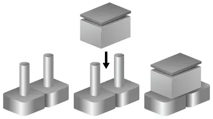
A jumper is the simplest kind of electric switch. It consists of two metal pins and a cap. When setting the jumpers, ensure that the jumper caps are placed on the correct pins. When the jumper cap is placed on both pins, the jumper is short. If you remove the jumper cap, or place the jumper cap on just one pin, the jumper is open.
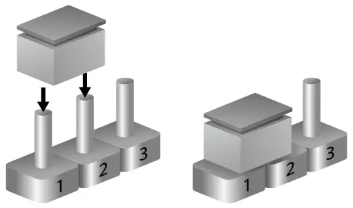
Refer to the illustrations below for examples of what the 2-pin and 3-pin jumpers look like when they are short (on) and open (off).
Two-Pin Jumpers: Open (Left) and Short (Right)
Three-Pin Jumpers: Pins 1 and 2 are Short
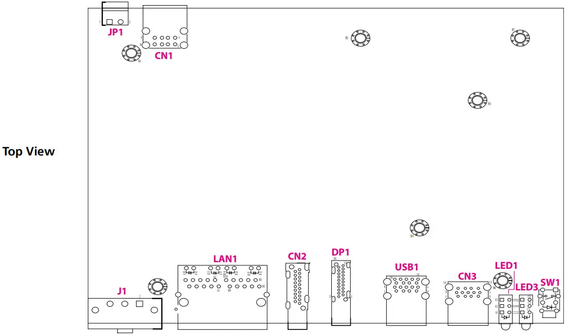
Locations of the Jumpers and Connectors for NISB 109
NISB 109
The figure below is the top view of the NISB 109 main board which is the main board used in NISE 109. It shows the locations of the jumpers and connectors.
 | 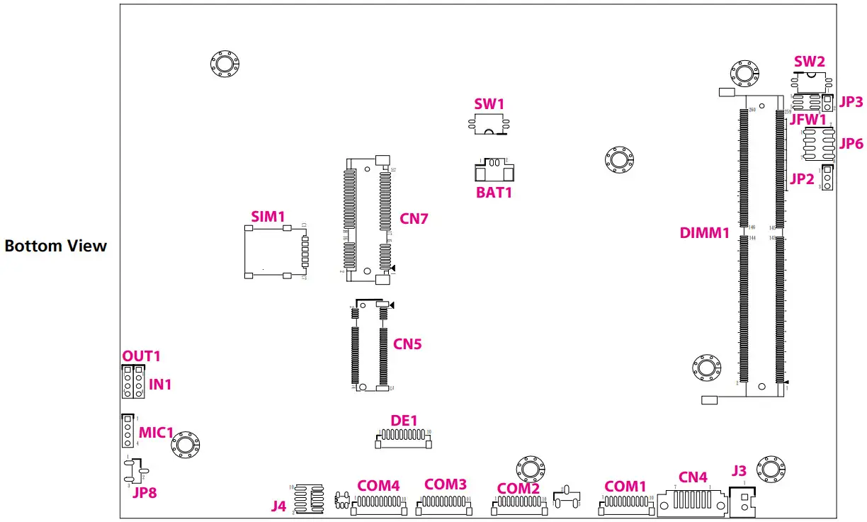 |
DIP Switches
Clear CMOS Switch
Connector type: 2×2 DIP switch
Connector location: SW3
![]()
| SW3 Clear CMOS | |
| 1-4 2-3 | Status |
| ON | Clease CMOS |
| OFF | Normal (Default) |
| Pin | Definition |
| 1 | I_RTCRSTL |
| 2 | I_RTCTESTL |
| 3 | GND |
| 4 | GND |
ATX/AT Mode Selection
Connector type: 2×2 DIP switch
Connector location: SW2
![]()
| AT/ATX Selection | ||
| 1-4 | 2-3 | MODE |
| ON | ON | AT (PWR BT available) |
| ON | OFF | AT (PWR BT invalid) |
| OFF | ON | ATX |
| Pin | Definition |
| 1 | PBT_PU |
| 2 | PBT_PU |
| 3 | ATX_PBT |
| 4 | AT_PWRBT# |
Connector Pin Definitions
External I/O Interfaces
USB2.0 Ports x2
Connector type: Dual USB 2.0 Ports
Connector location: CN1
![]()
| Pin | Definition | Pin | Definition |
| 1 | 5VSBUSB2 | 2 | IUSB2N0 |
| 3 | IUSB2P0 | 4 | GND |
| 5 | 5VSBUSB2 | 6 | IUSB2N3 |
| 7 | IUSB2P3 | 8 | GND |
| MH1 | NEAR_GND | MH2 | NEAR_GND |
| MH3 | NEAR_GND | MH4 | NEAR_GND |
USB3.0 + USB2.0 Ports
Connector location: CN3
![]()
| Pin | Definition | Pin | Definition |
| 1 | 5VSBUSB3 | 2 | IUSB2N5 |
| 3 | IUSB2P5 | 4 | GND |
| 5 | IUSB3CRXN0 | 6 | IUSB3CRXP0 |
| 7 | GND | 8 | IUSB3CTXN0 |
| 9 | IUSB3CTXP0 | 10 | 5VSBUSB3 |
| 11 | 1USB2N1 | 12 | 1USB2P1 |
| 13 | GND | MH1 | CHASIS_GND |
| MH2 | CHASIS_GND | MH3 | CHASIS_GND |
| MH4 | CHASIS_GND |
USB3.0 Ports x2
Connector type: Dual USB 3.0 Ports
Connector location: USB1
![]()
| Pin | Definition | Pin | Definition |
| 1 | 5VSBUSB1 | 2 | IUSB2N2 |
| 3 | IUSB2P2 | 4 | GND |
| 5 | IUSB3CRXN1 | 6 | IUSB3CRXP1 |
| 7 | GND | 8 | IUSB3CTXN1 |
| 9 | IUSB3CTXP1 | 10 | 5VSBUSB1 |
| 11 | IUSB2N4 | 12 | IUSB2P4 |
| 13 | GND | 14 | IUSB3CRXN2 |
| 15 | IUSB3CRXP2 | 16 | GND |
| 17 | IUSB3CTXN2 | 18 | IUSB3CTXP2 |
| MH1 | CHASIS_GND | MH2 | CHASIS_GND |
| MH3 | CHASIS_GND | MH4 | CHASIS_GND |
HDMI Connector
Connector type: HDMI port
Connector location: CN2
![]()
| Pin | Definition | Pin | Definition |
| 1 | HDMITX2P1 | 2 | GND |
| 3 | HDMITX2N1 | 4 | HDMITX1P1 |
| 5 | GND | 6 | HDMITX1N1 |
| 7 | HDMITX0P1 | 8 | GND |
| 9 | HDMITX0N1 | 10 | HDMICLKP1 |
| 11 | GND | 12 | HDMICLKN1 |
| 13 | NC | 14 | NC |
| 15 | HDMIDDCSCL | 16 | HDMIDDCSDA |
| 17 | GND | 18 | VCC5HDMI |
| 19 | HDMIHPD | NH1 | NC |
| NH2 | NC | MH1 | CHASIS_GND |
| MH2 | HDMIMH2 | MH3 | CHASIS_GND |
| MH4 | NC |
DisplayPort Connector
Connector type: DisplayPort
Connector location: DP1
![]()
| Pin | Definition | Pin | Definition |
| 1 | LANE0_P | 2 | GND |
| 3 | LANE0_N | 4 | LANE1_P |
| 5 | GND | 6 | LANE1_N |
| 7 | LANE2_P | 8 | GND |
| 9 | LANE2_N | 10 | LANE3_P |
| 11 | GND | 12 | LANE3_N |
| 13 | CONFIG1 | 14 | CONFIG2 |
| 15 | AUX_P | 16 | GND |
| 17 | AUX_N | 18 | DPHPD |
| 19 | RETURN | 20 | 3V3DPPWR |
| NH1 | NC | NH2 | NC |
| MH1 | CHASIS_GND | MH2 | CHASIS_GND |
| MH3 | CHASIS_GND | MH4 | NC |
LAN Ports x2
Connector type: RJ45 x2
Connector location: LAN1
![]()
| Pin | Definition | Pin | Definition |
| A1 | LAN1MDI0P | A2 | LAN1MDI0N |
| A3 | LAN1MDI1P | A4 | LAN1MDI1N |
| A5 | LAN1TVCC1 | A6 | GND |
| A7 | LAN1MDI2P | A8 | LAN1MDI2N |
| A9 | LAN1MDI3P | A10 | LAN1MDI3N |
| A11 | LAN1LINK1000L | A12 | LAN1LINK100L1 |
| A13 | LAN1LEDACTL | A14 | LAN1LEDPWR |
| NH1 | NC | MH1 | CHASIS_GND |
| B1 | LAN2MDI0P | B2 | LAN2MDI0N |
| B3 | LAN2MDI1P | B4 | LAN2MDI1N |
| B5 | LAN2TVCC1 | B6 | GND |
| B7 | LAN2MDI2P | B8 | LAN2MDI2N |
| B9 | LAN2MDI3P | B10 | LAN2MDI3N |
| B11 | LAN2LINK1000L | B12 | LAN2LINK100L1 |
| B13 | LAN2LEDACTL | B14 | LAN2LEDPWR |
| NH2 | NC | MH2 | CHASIS_GND |
Internal Connectors
SATA Connector
Connector type: Standard Serial ATAII 7P (1.27mm, SATA-M-180)
Connector location: CN4
![]()
| Pin | Definition | Pin | Definition |
| 1 | GND | 2 | SATATXP0 |
| 3 | SATATXN0 | 4 | GND |
| 5 | SATARXN0 | 6 | SATARXP0 |
| 7 | GND | MH1 | GND |
| MH2 | GND |
GPIO Connector
Connector type: 2×5, 10-pin header
Connector location: J4
![]()
| Pin | Definition | Pin | Definition |
| 1 | GPIO_PWR | 2 | GND |
| 3 | GPO0_OUT | 4 | GPI0_IN |
| 5 | GPO1_OUT | 6 | GPI1_IN |
| 7 | GPO2_OUT | 8 | GPI2_IN |
| 9 | GPO3_OUT | 10 | GPI3_IN |
COM1 Connector
Connector type: 1×10, 10-pin header
Connector location: COM1
![]()
| Pin | Definition | Pin | Definition |
| 1 | COM1DCDL | 2 | COM1RXD |
| 3 | COM1TXD | 4 | COM1DTRL |
| 5 | GND | 6 | COM1DSRL |
| 7 | COM1RTSL | 8 | COM1CTSL |
| 9 | COM1RIL | 10 | GND |
| MH1 | GND | MH2 | NC |
COM2 Connector
Connector type: 1×10, 10-pin header
Connector location: COM2
![]()
| Pin | Definition | Pin | Definition |
| 1 | COM2DCDL | 2 | COM2RXD |
| 3 | COM2TXD | 4 | COM2DTRL |
| 5 | GND | 6 | COM2DSRL |
| 7 | COM2RTSL | 8 | COM2CTSL |
| 9 | COM2RIL_CON | 10 | GND |
| MH1 | GND | MH2 | NC |
COM3 Connector
Connector type: 1×10, 10-pin header
Connector location: COM3
![]()
| Pin | Definition | Pin | Definition |
| 1 | COM3DCDL | 2 | COM3RXD |
| 3 | COM3TXD | 4 | COM3DTRL |
| 5 | GND | 6 | COM3DSRL |
| 7 | COM3RTSL | 8 | COM3CTSL |
| 9 | COM3RIL | 10 | GND |
| MH1 | GND | MH2 | GND |
COM4 Connector
Connector type: 1×10, 10-pin header
Connector location: COM4
![]()
| Pin | Definition | Pin | Definition |
| 1 | COM4DCDL | 2 | COM4RXD |
| 3 | COM4TXD | 4 | COM4DTRL |
| 5 | GND | 6 | COM4DSRL |
| 7 | COM4RTSL | 8 | COM4CTSL |
| 9 | COM4RIL | 10 | GND |
| MH1 | GND | MH2 | GND |
DE1 Connector
Connector type: 1×10, 10-pin header
Connector location: DE1
![]()
| Pin | Definition | Pin | Definition |
| 1 | GND | 2 | I_PLTRSTL |
| 3 | I_ESPICLK | 4 | I_ESPICS0L |
| 5 | I_ESPIIO3 | 6 | I_ESPIIO2 |
| 7 | I_ESPIIO1 | 8 | I_ESPIIO0 |
| 9 | I_ESPIRSTL | 10 | 3VSB |
| MH1 | GND | MH2 | GND |
Power Button
Connector location: SW1
![]()
| Pin | Definition | Pin | Definition |
| 1 | GND | 2 | ATX_PBT |
| 3 | ATX_PBT | 4 | GND |
| A1 | PWRLED_N | C1 | N16937976 |
| MH1 | NC | MH2 | NC |
Audio Line In Connector
Connector type: 1×4, 4-pin header
Connector location: IN1
![]()
| Pin | Definition |
| 1 | LINE1-L1 |
| 2 | AGND |
| 3 | LINEIN_JD |
| 4 | LINE1-R1 |
Audio Line Out Connector
Connector type: 1×4, 4-pin header
Connector location: OUT1
![]()
| Pin | Definition |
| 1 | LINE_OUT_LC |
| 2 | AGND |
| 3 | LINEOUT_JD |
| 4 | LINE_OUT_RC |
Audio MIC In Connector
Connector type: 1×4, 4-pin header
Connector location: MIC1
![]()
| Pin | Definition |
| 1 | MIC_OUT-L |
| 2 | AGND |
| 3 | MIC_JD |
| 4 | MIC_OUT-R |
Vin Power Terminal Block
Connector type: 1×3, 3-pin header
Connector location: J1
![]()
| Pin | Definition | Pin | Definition |
| 1 | VINP1 | 2 | VINVSS |
| 3 | VINPGND | NH1 | NC |
| NH2 | NC |
LCD Backlight Connector
Connector type: 1×7, 7-pin header
Connector location: J2
![]()
| Pin | Definition | Pin | Definition |
| 1 | VCC5 | 2 | V_INV |
| 3 | V_INV | 4 | 3V5VEDPBKLCTL |
| 5 | GND | 6 | GND |
| 7 | BUFEDPBKLEN |
SATA Power Connector
Connector type: 1×2, 2-pin header
Connector location: J3
![]()
| Pin | Definition |
| 1 | SATAPWR |
| 2 | GND |
Flash BIOS Pin Header
Connector type: 2×3, 6-pin header
Connector location: JFW1
![]()
| Pin | Definition | Pin | Definition |
| 1 | VSPI | 2 | GND |
| 3 | BIOSSPICSL0 | 4 | BIOSSPICLK |
| 5 | BIOSSPISO | 6 | BIOSSPISI |
Remote Power On/Off THR
Connector type: 1×2, 2-pin header
Connector location: JP1
![]()
| Pin | Definition |
| 1 | GND |
| 2 | PWRBTN#_J |
Panel LED Pin Header
Connector type: 1×3, 3-pin header
Connector location: JP2
![]()
| Pin | Definition |
| 1 | N17473943 |
| 2 | GND |
| 3 | N17472512 |
Reset Pin Header
Connector type: 1×2, 2-pin header
Connector location: JP3
![]()
| Pin | Definition |
| 1 | SYSRESETN |
| 2 | GND |
LCD Backlight Control Voltage Select Pin Header
Connector type: 1×3, 3-pin header
Connector location: JP4
![]()
| Pin | Definition |
| 1 | VCC5 |
| 2 | 3V5BKLPWR |
| 3 | VCC3 |
LCD Voltage Select Pin Header
Connector type: 1×3, 3-pin header
Connector location: JP5
![]()
| Pin | Definition |
| 1 | VCC5 |
| 2 | 3V5VLCDPWR |
| 3 | VCC3 |
USB2.0 Port Pin Header
Connector type: 2×4, 8-pin header
Connector location: JP6
![]()
| Pin | Definition | Pin | Definition |
| 1 | INTUSB2PWR | 2 | GND |
| 3 | USB2N6 | 4 | USB2P9 |
| 5 | USB2P6 | 6 | USB2N9 |
| 7 | GND | 8 | INTUSB2PWR |
COM2 Pin9 R#/5V Select Pin Header
Connector type: 1×3, 3-pin header
Connector location: JP7
![]()
| Pin | Definition |
| 1 | COM2RIL |
| 2 | COM2RIL_CON |
| 3 | VCC5 |
Remote Power On/Off & S3 Pin Header
Connector type: 1×3, 3-pin header
Connector location: JP8
![]()
| Pin | Definition |
| 1 | SLP_S3#_J |
| 2 | GND |
| 3 | PWRBTN#_J |
Nano SIM Connector
Connector location: SIM1
![]()
| Pin | Definition | Pin | Definition |
| C1 | UIM_PWR | C2 | UIM_RESET |
| C3 | UIM_SIM_CLK | C5 | GND |
| C6 | UIM_VPP | C7 | UIM_DATA |
| MH1 | GND | MH2 | GND |
| MH3 | GND | MH4 | GND |
LVDS Connector 1 of 2 (Reserved for APPC/IPPC project)
Connector location: LV1
![]()
| Pin | Definition | Pin | Definition |
| 1 | CHGPIO0 | 2 | CHGPIO1 |
| 3 | VCC_LCD | 4 | CH_LVDSTP0 |
| 5 | CH_LVDSTP3 | 6 | CH_LVDSTN0 |
| 7 | CH_LVDSTN3 | 8 | VCC_LCD |
| 9 | GND | 10 | CH_LVDSTP1 |
| 11 | CH_LVDSCLKP1 | 12 | CH_LVDSTN1 |
| 13 | CH_LVDSCLKN1 | 14 | GND |
| 15 | GND | 16 | V_INV |
| 17 | CH_LVDSTP2 | 18 | V_INV |
| 19 | CH_LVDSTN2 | 20 | GND |
| NH1 | NC | NH2 | NC |
| MH1 | GND | MH2 | GND |
LVDS Connector 2 of 2 (Reserved for APPC/IPPC project)
Connector location: LV2
![]()
| Pin | Definition | Pin | Definition |
| 1 | CHGPIO2 | 2 | CHGPIO3 |
| 3 | VCC_LCD | 4 | CH_LVDSTP4 |
| 5 | CH_LVDSTP7 | 6 | CH_LVDSTN4 |
| 7 | CH_LVDSTN7 | 8 | VCC_LCD |
| 9 | GND | 10 | CH_LVDSTP5 |
| 11 | CH_LVDSCLKP2 | 12 | CH_LVDSTN5 |
| 13 | CH_LVDSCLKN2 | 14 | GND |
| 15 | GND | 16 | V_INV |
| 17 | CH_LVDSTP6 | 18 | V_INV |
| 19 | CH_LVDSTN6 | 20 | GND |
| NH1 | NC | NH2 | NC |
| MH1 | GND | MH2 | GND |
RTC Battery
Connector location: BAT1
![]()
| Pin | Definition |
| 1 | GND |
| 2 | 3V_BAT1 |
| MH1 | GND |
| MH2 | GND |
M.2 Key B Connector
Connector location: CN5
![]()
| Pin | Definition | Pin | Definition |
| 1 | M2BCONFIG3 | 2 | M2LTEPWR |
| 3 | GND | 4 | M2LTEPWR |
| 5 | GND | 6 | S_GP42 |
| 7 | I_USB2P7 | 8 | S_GP43 |
| 9 | I_USB2N7 | 10 | NC |
| 11 | M2REFCLK | 12 | |
| 20 | NC | 21 | M2BCONFIG0 |
| 22 | NC | 23 | LTEPEWAKE2 |
| 24 | NC | 25 | NC |
| 26 | NC | 27 | GND |
| 28 | UIM_VPP | 29 | USB3RXN3 |
| 30 | UIM_RESET | 31 | USB3RXP3 |
| 32 | UIM_CLK | 33 | GND |
| 34 | UIM_DATA | 35 | USB3TXN3 |
| 36 | UIM_PWR | 37 | USB3TXP3 |
| Pin | Definition | Pin | Definition |
| 38 | NC | 39 | GND |
| 40 | NC | 41 | PCIESATARP |
| 42 | NC | 43 | PCIESATARN |
| 44 | NC | 45 | GND |
| 46 | NC | 47 | PCIESATATN |
| 48 | NC | 49 | PCIESATATP |
| 50 | LTEPERSTL | 51 | GND |
| 52 | NC | 53 | M2REFCLKN |
| 54 | LTEPEWAKE1 | 55 | M2REFCLKP |
| 56 | NC | 57 | GND |
| 58 | NC | 59 | NC |
| 60 | NC | 61 | NC |
| 62 | NC | 63 | NC |
| 64 | NC | 65 | NC |
| 66 | NC | 67 | M2LTERSTL |
| 68 | M2B_SUSCLK | 69 | M2BCONFIG1 |
| 70 | M2LTEPWR | 71 | GND |
| 72 | M2LTEPWR | 73 | GND |
| 74 | M2LTEPWR | 75 | M2BCONFIG2 |
| MH1 | GND | MH2 | GND |
| NH1 | NC | NH2 | NC |
Mini PCIe Connector
Connector location: CN7
![]()
| Pin | Definition | Pin | Definition |
| 1 | I_WAKEL | 2 | 3VSB_MINILTE |
| 3 | NC | 4 | GND |
| 5 | NC | 6 | 1V5_MINI |
| 7 | I_PCIECLKREQL5 | 8 | UIM_PWR |
| 9 | GND | 10 | UIM_DATA |
| 11 | I_PCIECLKOUTN5 | 12 | UIM_CLK |
| 13 | I_PCIECLKOUTP5 | 14 | UIM_RESET |
| 15 | GND | 16 | UIM_VPP |
| 17 | NC | 18 | GND |
| 19 | NC | 20 | LTEDISL |
| 21 | GND | 22 | LTERSTL |
| 23 | I_PCIERXN4 | 24 | 3VSB_MINILTE |
| 25 | I_PCIERXP4 | 26 | GND |
| 27 | GND | 28 | 1V5_MINI |
| 29 | GND | 30 | I_SMB3P3CLK |
| 31 | I_PCIETXN4 | 32 | I_SMB3P3DATA |
| Pin | Definition | Pin | Definition |
| 33 | NC | 34 | GND |
| 35 | NC | 36 | I_USB2N8 |
| 37 | NC | 38 | I_USB2P8 |
| 39 | NC | 40 | GND |
| 41 | NC | 42 | NC |
| 43 | NC | 44 | NC |
| 45 | LTEPERSTL | 46 | NC |
| 47 | NC | 48 | 1V5_MINI |
| 49 | LTEPEWAKE1 | 50 | GND |
| 51 | NC | 52 | 3VSB_MINILTE |
| MH1 | NC | MH2 | GND |
| MH3 | NC | NH4 | NC |
| MH5 | NC | MH6 | NC |
| NH1 | NC | NH2 | NC |
Chapter 3: System Setup
Removing the Chassis Cover![]() Prior to removing the chassis cover, make sure the unit’s power is off and disconnected from the power sources to prevent electric shock or system damage.
Prior to removing the chassis cover, make sure the unit’s power is off and disconnected from the power sources to prevent electric shock or system damage.
- Remove the six mounting screws from the bottom cover.

- With the screws removed, lift up the cover and remove it from the chassis.

Installing a SO-DIMM Memory Module
![]() Note:
Note:
Remove the bottom cover before installing a SO-DIMM.
- Locate the SO-DIMM socket.

- Insert the module into the socket at an approximately 30-degree angle.
The ejector tabs at the ends of the socket will automatically snap into the locked position to hold the module in place.
- Push the module down until the clips on both sides of the socket lock into position.

Installing a SIM Card
- Locate the SIM card holder on the board.

- Follow steps to release SIM holder cover.

- Insert your SIM card.

- Follow the steps to lock the SIM holder.

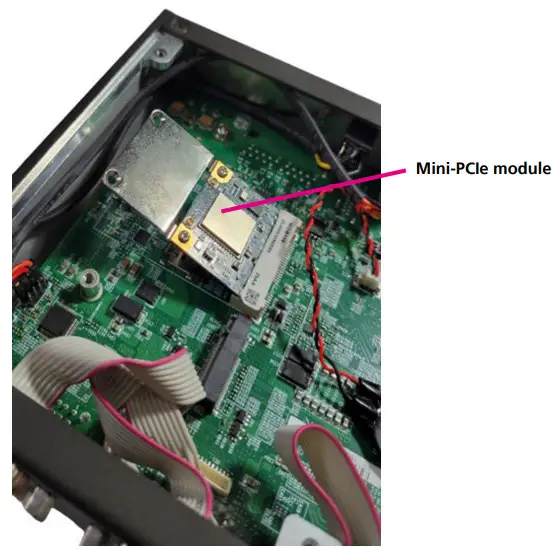
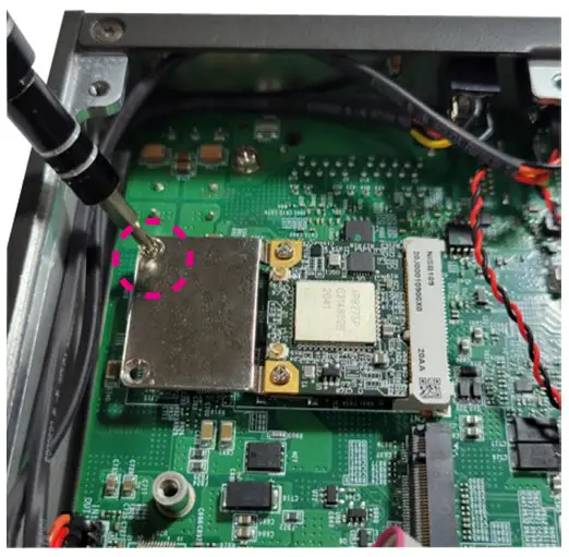
Installing a Mini-PCIe Module
- Locate the mini-PCIe slot on the board.

- Install the mini-PCIe bracket to the mini-PCIe module.
(When using a half-size module)
- Insert the WLAN module into the mini-PCIe slot at 45-degree angle until the gold-plated connector on the edge of the module completely disappears into the slot.

- Push the module down and secure it with a screw.

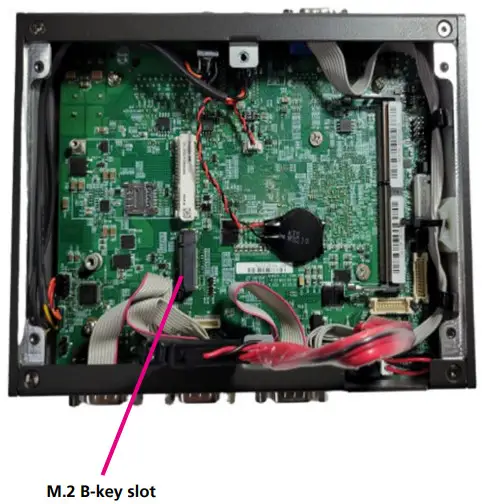
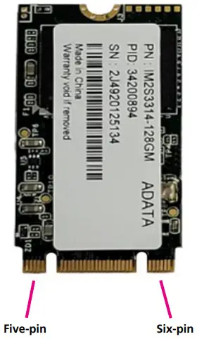
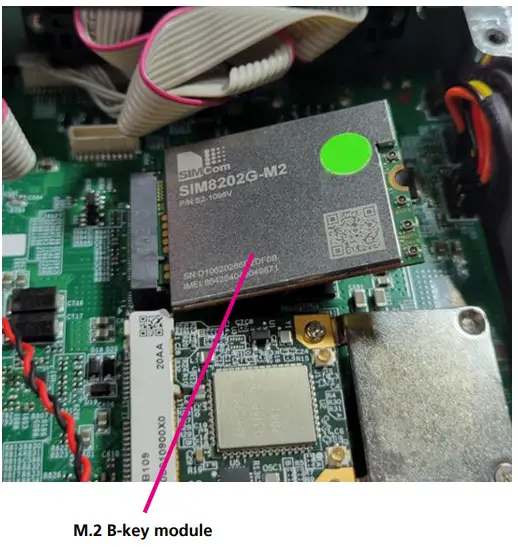
Installing an M.2 Module (2242)
- Locate the M.2 B-key slot on the board.

- Make sure the gold-plated six-pin connector on the edge of the module is on the left, while the five-pin connector is on the right.

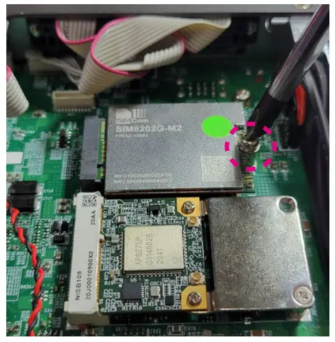
- Insert the M.2 module into the M.2 slot at 45-degree angle until the gold-plated connector on the edge of the module completely disappears into the slot.

- Push the module down and secure it with a screw.

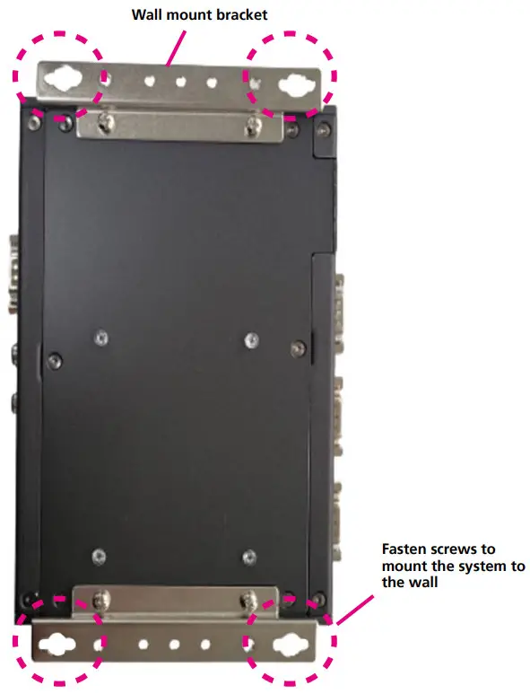
Wall Mounting Instructions
To mount the system on to a wall or some other surface using the two mounting brackets, please follow the steps below.
- Turn the system over. Align the two retention screw holes in each bracket with the retention screw holes on the sides of the bottom surface.
- Secure the brackets to the system by inserting two retention screws into each bracket.
- Drill holes in the intended installation surface.
- Align the mounting holes on the sides of the mounting brackets with the predrilled holes on the mounting surface.
- Insert four retention screws, two in each bracket, to secure the system to the wall.
![]() Note:
Note:
Specification of the wall mount screw:
Round Head Screw Long Fei: P6#32Tx 1/ 4/ SW7*0.8 w/Spring+Flat Washer
CHAPTER 4: Bios setup
This chapter describes how to use the BIOS setup program for NISE 109. The BIOS screens provided in this chapter are for reference only and may change if the BIOS is updated in the future.
To check for the latest updates and revisions, visit the NexAIoT website at www.nexaiot.com.
About BIOS Setup
The BIOS (Basic Input and Output System) Setup program is a menu driven utility that enables you to make changes to the system configuration and tailor your system to suit your individual work needs. It is a ROM-based configuration utility that displays the system’s configuration status and provides you with a tool to set system parameters. These parameters are stored in non-volatile battery-backed-up CMOS RAM that saves this information even when the power is turned off. When the system is turned back on, the system is configured with the values found in CMOS.
With easy-to-use pull down menus, you can configure items such as:
- Hard drives, diskette drives, and peripherals
- Video display type and display options
- Password protection from unauthorized use
- Power management features
The settings made in the setup program affect how the computer performs.
It is important, therefore, first to try to understand all the setup options, and second, to make settings appropriate for the way you use the computer.
When to Configure the BIOS
- This program should be executed under the following conditions:
- When changing the system configuration
- When a configuration error is detected by the system and you are prompted to make changes to the setup program
- When resetting the system clock
- When redefining the communication ports to prevent any conflicts
- When making changes to the Power Management configuration
- When changing the password or making other changes to the security setup
Normally, CMOS setup is needed when the system hardware is not consistent with the information contained in the CMOS RAM, whenever the CMOS RAM has lost power, or the system features need to be changed.
Default Configuration
Most of the configuration settings are either predefined according to the Load Optimal Defaults settings which are stored in the BIOS or are automatically detected and configured without requiring any actions. There are a few settings that you may need to change depending on your system configuration.
Entering Setup
When the system is powered on, the BIOS will enter the Power-On Self Test (POST) routines. These routines perform various diagnostic checks; if an error is encountered, the error will be reported in one of two different ways:
- If the error occurs before the display device is initialized, a series of beeps will be transmitted.
- If the error occurs after the display device is initialized, the screen will display the error message.
Powering on the computer and immediately pressing![]() allows you to enter Setup.
allows you to enter Setup.
| Key | Function |
| Moves the highlight left or right to select a menu. | |
| Moves the highlight up or down between sub-menu or fields. | |
| Exits the BIOS Setup Utility. | |
| Scrolls forward through the values or options of the highlighted field. | |
| Scrolls backward through the values or options of the highlighted field. | |
| Selects a field. | |
| Displays General Help. | |
| Load previous values. | |
| Load optimized default values. | |
| Saves and exits the Setup program. | |
| Press <Enter> to enter the highlighted sub-menu. |
Scroll Bar
When a scroll bar appears to the right of the setup screen, it indicates that there are more available fields not shown on the screen. Use the up and down arrow keys to scroll through all the available fields.
Submenu
When “▶” appears on the left of a particular field, it indicates that a submenu which contains additional options are available for that field. To display the submenu, move the highlight to that field and press![]() .
.
BIOS Setup Utility
Once you enter the AMI BIOS Setup Utility, the Main Menu will appear on the screen. The main menu allows you to select from several setup functions and one exit. Use arrow keys to select among the items and press![]() to accept or enter the submenu.
to accept or enter the submenu.
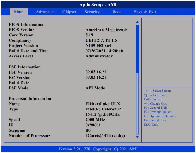
Main
The Main menu is the first screen that you will see when you enter the BIOS Setup Utility.
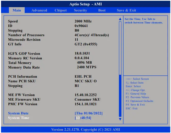
System Date
The date format is <day>, <month>, <date>, <year>. Day displays a day, from Monday to Sunday. Month displays the month, from January to December. Date displays the date, from 1 to 31. Year displays the year, from 2005 to 2099.
System Time
The time format is <hour>, <minute>, <second>. The time is based on the 24-hour military-time clock. For example, 1 p.m. is 13:00:00. Hour displays hours from 00 to 23. Minute displays minutes from 00 to 59. Second displays seconds from 00 to 59.
Advanced
The Advanced menu allows you to configure your system for basic operation.
Some entries are defaults required by the system board, while others, if enabled, will improve the performance of your system or let you set some features according to your preference.![]() Setting incorrect field values may cause the system to malfunction.
Setting incorrect field values may cause the system to malfunction.
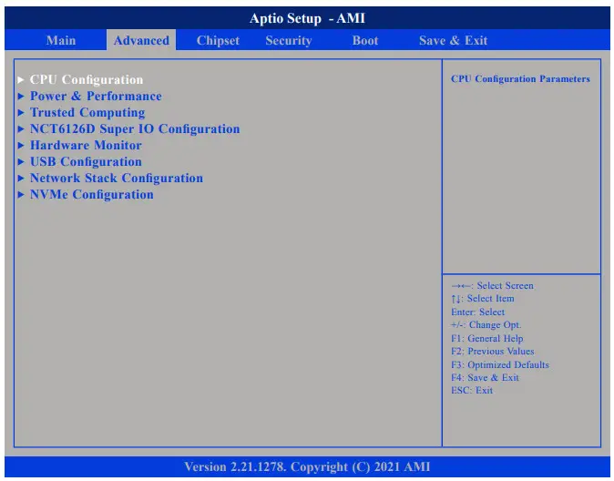
CPU Configuration
This section is used to configure the CPU.
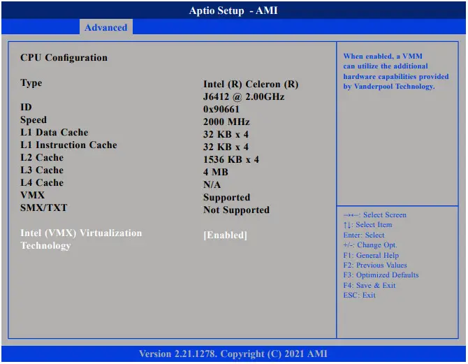
Intel® Virtualization Technology
When this field is set to Enabled, the VMM can utilize the additional hardware capabilities provided by Vanderpool Technology.
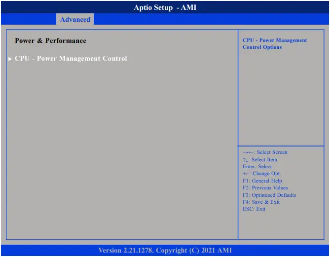
Power & Performance
This section is used to configure the power management features of the CPU.
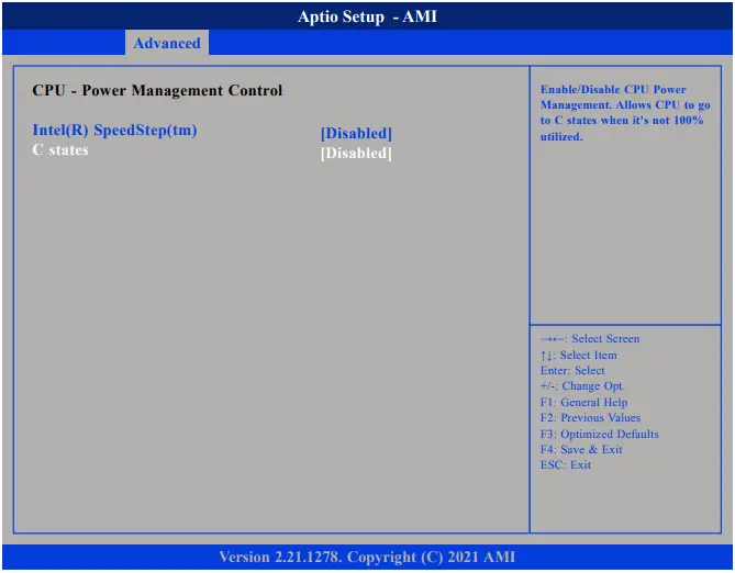
Intel® SpeedStep™ Allows more than two frequency ranges to be supported.
C states
Enable/Disable CPU Power Management. Allows CPU to go to C states when it’s not 100% utilized.
Trusted Computing
This section is used to configure Trusted Platform Module (TPM) settings.
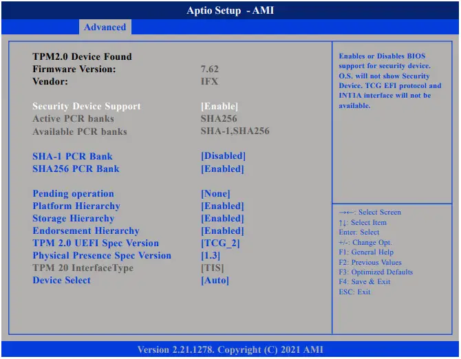
Security Device Support
Enables or disables BIOS support for security device. O.S will not show Security Device. TCG EFI protocol and INT1A interface will not be available.
SHA-1 PCR Bank
Enables or disables SHA-1 PCR Bank.
SHA256 PCR Bank
Enables or disables SHA256 PCR Bank.
Pending operation
Schedules an operation for the security device.
Platform Hierarchy
Enables or disables platform hierarchy.
Storage Hierarchy
Enables or disables storage hierarchy.
Endorsement Hierarchy
Enables or disables endorsement hierarchy.
TPM2.0 UEFI Spec Version
Configures the TPM 2.0 UEFI spec version.
Physical Presence Spec Version
Configures the physical presence spec version. Select to tell O.S. to support PPI Spec Version 1.2 or 1.3. Note some HCK tests might not support 1.3.
Device Select
Configures the TPM version. TPM 1.2 will restrict support to TPM 1.2 devices and TPM 2.0 will restrict support to TPM 2.0 devices. Auto will support both TPM 1.2 and 2.0 devices with the default set to TPM 2.0 devices if not found, and TPM 1.2 devices will be enumerated.
NCT6126D Super IO Configuration
This section is used to configure the serial ports.
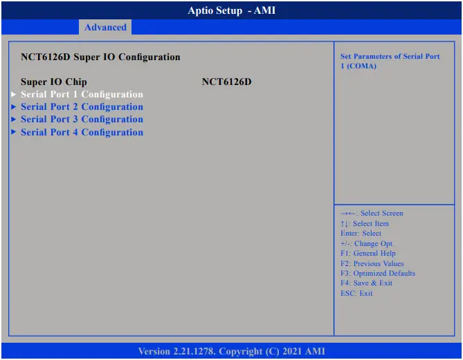
Super IO Chip
Displays the Super I/O chip used on the board.
Serial Port 1 to Serial Port 4 Configuration
Configuration settings for serial port 1 to port 4.
Serial Port 1 Configuration
This section is used to configure serial port 1.

Serial Port
Enables or disables the serial port.
Onboard Serial Port Mode
Select this to change the serial port mode to RS232, RS422, RS485 w/o Terminator, or RS485 W/ Terminator.
Terminal resistor
Enable or disable terminal resistor.
Serial Port 2 Configuration
This section is used to configure serial port 2.
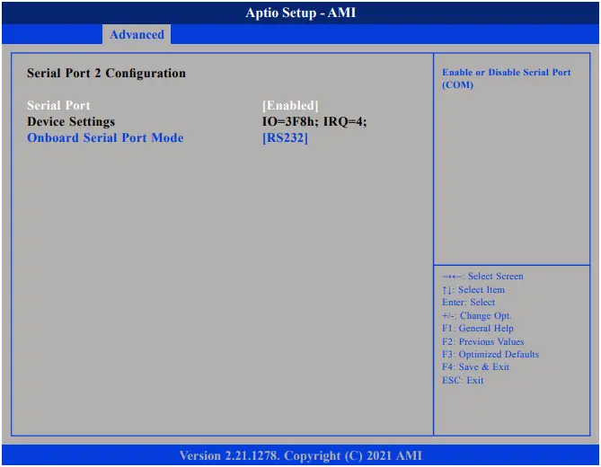
Serial Port
Enables or disables the serial port.
Onboard Serial Port Mode
Select this to change the serial port mode to RS232, RS422, RS485 w/o Terminator, or RS485 W/ Terminator.
Terminal resistor
Enable or disable terminal resistor.
Serial Port 3 Configuration
This section is used to configure serial port 3.
Serial Port
Enables or disables the serial port.
Onboard Serial Port Mode
Select this to change the serial port mode to RS232, RS422, RS485 w/o Terminator, or RS485 W/ Terminator.
Terminal resistor
Enable or disable terminal resistor.
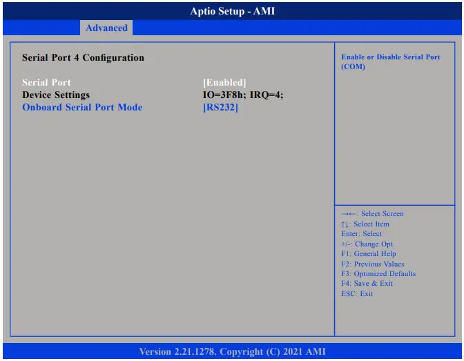
Serial Port 4 Configuration
This section is used to configure serial port 4.
Serial Port
Enables or disables the serial port.
Onboard Serial Port Mode
Select this to change the serial port mode to RS232, RS422, RS485 w/o Terminator, or RS485 W/ Terminator.
Terminal resistor
Enable or disable terminal resistor.
Hardware Monitor
This section is used to monitor hardware status such as temperature, fan speed and voltages.
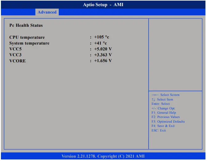
CPU temperature
Detects and displays the current CPU temperature.
System temperature
Detects and displays the current system temperature.
VCC5 to VCORE
Detects and displays the output voltages.
USB Configuration
This section is used to configure the USB.
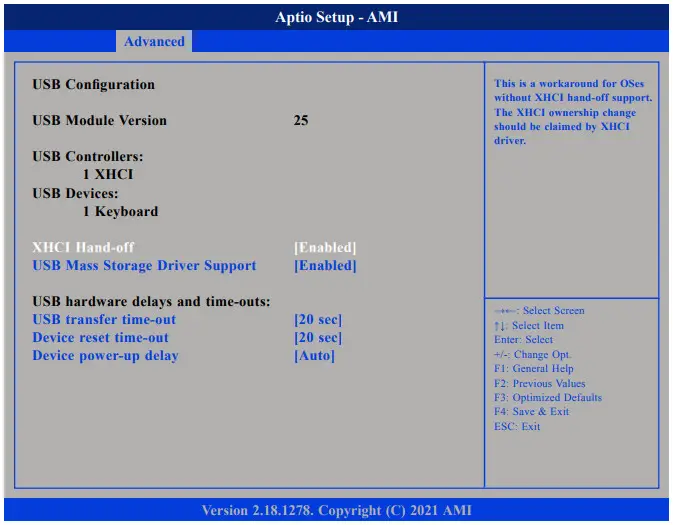
XHCI Hand-off
This is a workaround for OSs that does not support XHCI hand-off. The XHCI ownership change should be claimed by the XHCI driver.
USB Transfer Time-out
The time-out value for control, bulk, and Interrupt transfers.
Device reset time-out
Selects the USB mass storage device’s start unit command timeout.
Device Power-up Delay
Maximum time the value will take before it properly reports itself to the Host Controller. “Auto” uses default value: for a Root port it is 100 ms, for a Hub port the delay is taken from Hub descriptor.
Network Stack Configuration
This section is used to configure the network stack.
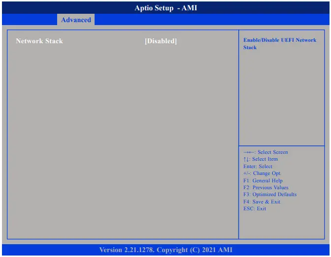
Network Stack
Enables or disables UEFI network stack.
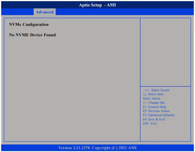
NVMe Configuration
This section is used to display information on the NVMe devices installed.
Chipset
This section gives you functions to configure the system based on the specific features of the chipset. The chipset manages bus speeds and access to system memory resources.
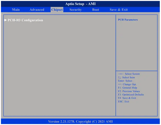
PCH-IO Configuration
Enters the PCH-IO Configuration submenu.
PCH-IO Configuration
This section is used to configure PCH-IO configuration.
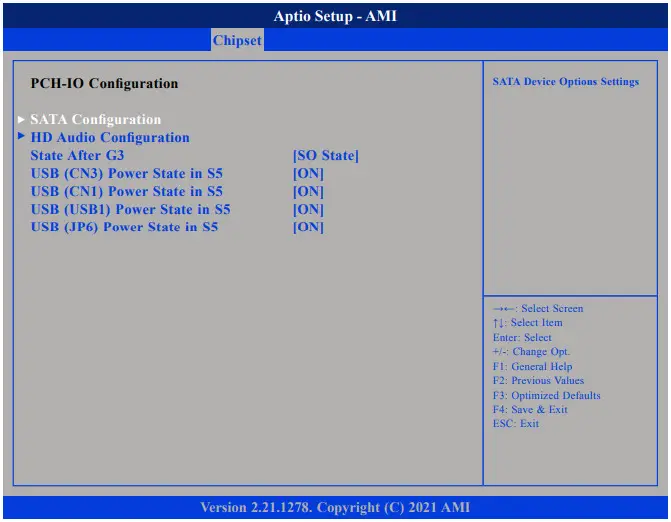
State After G3
Configures the power state when power is re-applied after a power failure (G3 state).
USB Power State in S5
Configures the USB power state in S5 for USB (CN3, CN1, USB1, JP6).
HD Audio Configuration
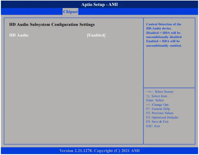
HD Audio
Control detection of the HD audio device.
Disabled – HD audio will be unconditionally disabled.
Enabled – HD audio will be unconditionally enabled.
Security
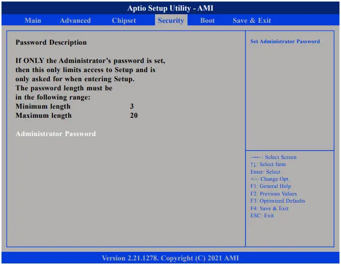
Administrator Password
Select this to reconfigure the administrator’s password.
Boot
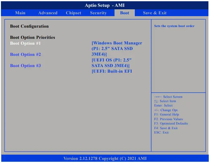
Boot Option Priorities
Adjust the boot sequence of the system. Boot Option #1 is the first boot device that the system will boot from, next will be #2 and so forth.
Save & Exit
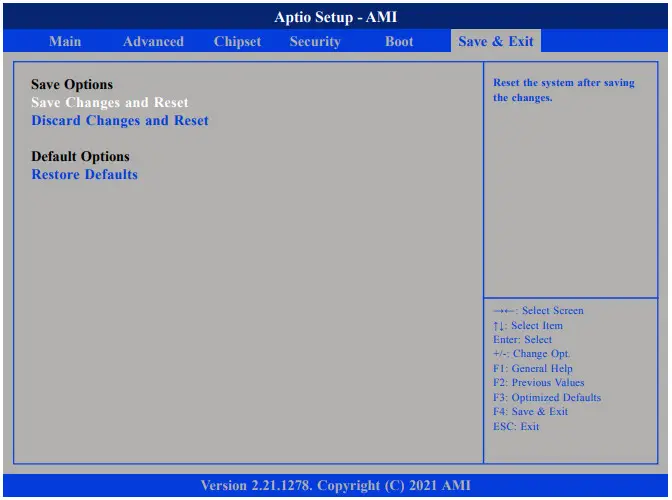
Save Changes and Reset
To save the changes and reset, select this field then press <Enter>. A dialog box will appear. Confirm by selecting Yes. You can also press <F4> to save and exit Setup.
Discard Changes and Reset
To exit the Setup utility and reset without saving the changes, select this field then press <Enter>. You may be prompted to confirm again before exiting. You can also press <ESC> to exit without saving the changes.
Restore Defaults
To restore the BIOS to default settings, select this field then press <Enter>. A dialog box will appear. Confirm by selecting Yes.
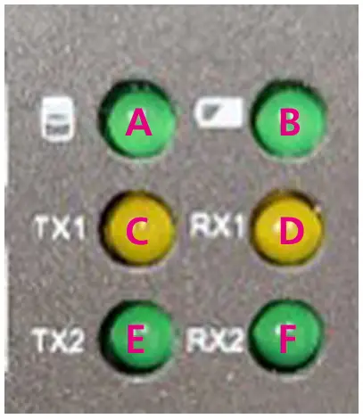
APPENDIX A: Led status
A: Storage (for HDD, SSD, M.2), light up when lower than 2.3V, Green
B: Battery, light up when lower than 2.3V, Green
C/D: TX/RX for COM1, Yellow
E/F: TX/RX for COM2, Green
![]() Copyright © 2021 NexAIoT Co., Ltd.
Copyright © 2021 NexAIoT Co., Ltd.
All Rights Reserved.
NISE 109
References
 The domain name is for sale!
 nexaiot.com
-
nexcobot
-
nexcobot
 æ ªå¼ä¼šç¤¾ãƒã‚¯ã‚¹ã‚³ãƒ ・ジャパン – IoTã€ãƒãƒœãƒƒãƒˆã€ã‚¹ãƒžãƒ¼ãƒˆãƒ»ãƒžãƒ‹ãƒ¥ãƒ•ã‚¡ã‚¯ãƒãƒ£ãƒªãƒ³ã‚°ã€ã‚¹ãƒžãƒ¼ãƒˆãƒ“ジãƒã‚¹ã€ITSã€ãƒãƒƒãƒˆãƒ¯ãƒ¼ã‚¯ã‚»ã‚ュリティ
-
新汉股份 - æ–°æ±‰å·¥æŽ§æœºï¼Œæ— é£Žæ‰‡å·¥æŽ§æœºï¼Œæ— é£Žæ‰‡å·¥ä¸šå¹³æ¿ç”µè„‘,嵌入å¼å·¥ä¸šä¸»æ¿ï¼Œæ•°å—æ ‡ç‰Œï¼Œæ™ºèƒ½è½¦è½½å¹³å°ï¼Œè½¦è½½ä¸€ä½“化,网络安全平å°
-
NEXCOM International Co., LTD.
-
NEXCOM - IoT, Robot, Smart Manufacturing, Smart Business, ITS, Network Security
-
NEXCOM - IoT, Robot, Smart Manufacturing, Smart Business, ITS, Network Security
-
边缘AI计算机_边缘计算盒子_AI边缘计算_边缘计算服务器_新汉工控机_无风扇工控机_嵌入式工控机_汉智兴科技
-
兴汉网际,云互联,网络安全平台,国产化平台,物联网网关,网络扩展模块


