
Crown XLi1500 450-Watt at 4Ω Power Amplifier

Introduction
Obtaining Other Language Versions To obtain information in another language about the use of this product, please contact your local Crown Distributor. If you need assistance locating your local distributor, please contact Crown at 574-294-8000.
This manual does not include all of the details of design, production, or variations of the equipment. Nor does it cover every possible situation which may arise during installation, operation or maintenance.
The information provided in this manual was deemed accurate as of the publication date. However, updates to this information may have occurred. To obtain the latest version of this manual, please visit the Crown website at www.crownaudio.com.
Later versions of this manual and additional information about this product may be available at the Crown website at www.crownaudio.com.
Trademark Notice: Crown and Crown Audio are registered trademarks of Crown International. Other trademarks are the property of their respective owners.©2012 by Harman International. 1718 W. Mishawaka Rd., Elkhart, Indiana 46517-9439 U.S.A. Telephone: 574-294-8000
IMPORTANT SAFETY INSTRUCTIONS
- Read these instructions.
- Keep these instructions.
- Heed all warnings.
- Follow all instructions.
- Do not use this apparatus near water.
- Clean only with a dry cloth.
- Do not block any ventilation openings. Install in accordance with the manufacturer’s instructions.
- Do not install near any heat sources such as radiators, heat registers, stoves, or other apparatus (including amplifiers) that produce heat.
- Do not defeat the safety purpose of the polarized or grounding-type plug. A polarized plug has two blades with one wider than the other. A grounding-type plug has two blades and a third grounding prong. The wide blade or the third prong is provided for your safety. If the provided plug does not fit into your outlet, consult an electrician for replacement of the obsolete outlet.
- Protect the power cord from being walked on or pinched, particularly at plugs, convenience receptacles, and the point where they exit from the apparatus.
- Only use attachments/accessories specified by the manu-facturer.
- Use only with a cart, stand, tripod, bracket, or table specified by the manufacturer, or sold with the apparatus. When a cart is used, use caution when moving the cart/apparatus combination to avoid injury from tip-over.
- Unplug this apparatus during lightning storms or when unused for long periods of time.
- Refer all servicing to qualified service personnel. Servicing is required when the apparatus has been damaged in any way, such as power-supply cord or plug is damaged, liquid has been spilled or objects have fallen into the apparatus, the apparatus has been exposed to rain or moisture, does not operate normally, or has been dropped.
- Use the mains plug to disconnect the apparatus from the mains.
- WARNING: TO REDUCE THE RISK OF FIRE OR ELECTRIC SHOCK, DO NOT EXPOSE THIS APPARATUS TO RAIN OR MOISTURE.
- WARNING: THIS APPLIANCE SHALL BE CONNECTED TO A MAINS SOCKET OUTLET WITH A PROTECTIVE EARTHING CONNECTION.
- DO NOT EXPOSE THIS EQUIPMENT TO DRIPPING OR SPLASHING AND ENSURE THAT NO OBJECTS FILLED WITH LIQUIDS, SUCH AS VASES, ARE PLACED ON THE EQUIPMENT.
- THE MAINS PLUG OF THE POWER SUPPLY CORD SHALL REMAIN READILY OPERABLE.
DANGER: TO PREVENT ELECTRIC SHOCK DO NOT REMOVE TOP OR BOTTOM COVERS. NO USER SERVICEABLE PARTS INSIDE. REFER SERVICING TO QUALIFIED SERVICE PERSONNEL.
WARNING: TO COMPLETELY DISCONNECT THIS EQUIPMENT FROM THE AC MAINS, DISCONNECT THE POWER SUPPLY CORD PLUG FROM THE AC RECEPTACLE. THE MAINS PLUG OF THE POWER SUPPLY CORD SHALL
WATCH FOR THESE SYMBOLS:
DANGER: The lightning bolt triangle is used to alert the user to the risk of electric shock.
WARNING: The exclamation point triangle is used to alert the user to important operating or maintenance instructions.
IMPORTANT
XLi Series amplifiers require Class 2 output wiring.
MAGNETIC FIELD
CAUTION! Do not locate sensitive high-gain equipment such as preamplifiers or tape decks directly above or below the unit. Be-cause this amplifier has a high power density, it has a strong mag-netic field which can induce hum into unshielded devices that are located nearby. The field is strongest just above and below the unit.
If an equipment rack is used, we recommend locating the amplifier(s) in the bottom of the rack and the preamplifier or other sensitive equipment at the top.
FCC COMPLIANCE NOTICE
This device complies with part 15 of the FCC rules. Operation is sub-ject to the following two conditions:
- This device may not cause harmful interference, and
- this device must accept any interference received, including interference that may cause undesired operation.
CAUTION: Changes or modifications not expressly approved by the party responsible for compliance could void the user’s authority to operate the equipment.
NOTE: This equipment has been tested and found to comply with the limits for a Class B digital device, pursuant to part 15 of the FCC Rules. These limits are designed to provide reasonable protection against harmful interference in a residential installation. This equip-ment generates, uses, and can radiate radio frequency energy and, if not installed and used in accordance with the instruction manual, may cause harmful interference to radio communications. However, there is no guarantee that interference will not occur in a particular installation. If this equipment does cause harmful interference to ra-dio or television reception, which can be determined by turning the equipment off and on, the user is encouraged to try to correct the interference by one or more of the following measures:
- Reorient or relocate the receiving antenna.
- Increase the separation between the equipment and receiver.
- Connect the equipment into an outlet on a circuit different from that to which the receiver is connected.
- Consult the dealer or an experienced radio/TV technician for help.
DECLARATION OF CONFORMITY
European Representative’s Name and Address: David J. Budge 10 Harvest Close Yateley GU46 6YS United Kingdom
Equipment Type: Commercial Audio Power Amplifiers Family Name: Xli
Model Names: XLi 800
EMC Standards:
- EN 55103-1:1997 Electromagnetic Compatibility – Product Family Standard for Audio, Video, Audio-Visual and Entertainment Lighting Control Apparatus for Professional Use, Part 1: Emissions
- EN 55103-1:1997 Magnetic Field Emissions-Annex A @ 10 cm and 20 cm
- EN 61000-3-2:2001 Limits for Harmonic Current Emissions (equipment input current less than or equal to 16 A per phase)
- EN 61000-3-3:2002 Limitation of Voltage Fluctuations and Flicker in Low-Voltage Supply Systems Rated Current less than or equal to16A
- EN 55022:2003 Limits and Methods of Measurement of Radio Disturbance Characteristics of ITE: Radiated, Class B Limits; Conducted, Class A
- EN 55103-2:1997 Electromagnetic Compatibility – Product Family Standard for Audio, Video, Audio-Visual and Entertainment Lighting Control Apparatus for Professional Use, Part 2: Immunity
- EN 61000-4-2:2001 Electrostatic Discharge Immunity (Environment E2-Criteria B, 4k V Contact, 8k V Air Discharge)
- EN 61000-4-3:2001 Radiated, Radio-Frequency, Electromagnetic Immunity (Environment E2, criteria A)
- EN 61000-4-4:2001 Electrical Fast Transient/Burst Immunity (Criteria B)
- EN 61000-4-5:2001 Surge Immunity (Criteria B)
- EN 61000-4-6:2003 Immunity to Conducted Disturbances Induced by Radio-Frequency Fields (Criteria A)
- EN 61000-4-11:2001 Voltage Dips, Short Interruptions and Voltage Variation
Safety Standard
IEC 60065: 2001 7th Ed. Safety Requirements – Audio Video and Similar Electronic Apparatus
I certify that the product identified above conforms to the requirements of the EMC Council Directive 89/336/EEC as amended by 92/31/EEC, and the Low Voltage Directive 73/23/EES as amended by 93/68/EEC.92/31/EEC, and the Low Voltage Directive 73/23/EES as amended by 93/68/EEC.
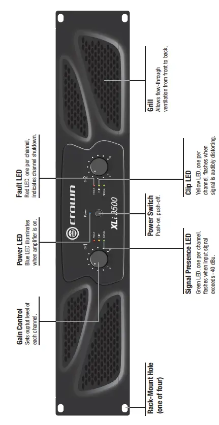
FRONT PANEL FEATURES
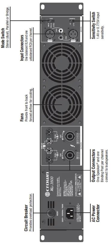
BACK PANEL FEATURES
WIRING
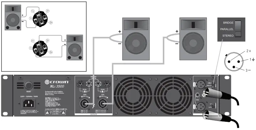
Stereo (Dual) Wiring Using the Speakon® Connectors
- See Figure 3. On the back panel, set the Output Mode Switch to STEREO.
- Wire the speakers to the Speakon® connectors as shown.
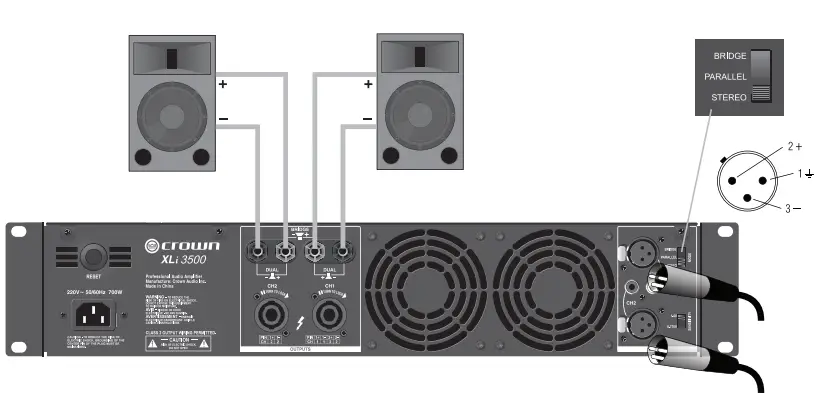
Stereo (Dual) Wiring Using the Binding Post Connectors
- See Figure 4. On the back panel, set the Output Mode Switch to STEREO.
- Wire the speakers to the binding post connectors as shown.
SETUP
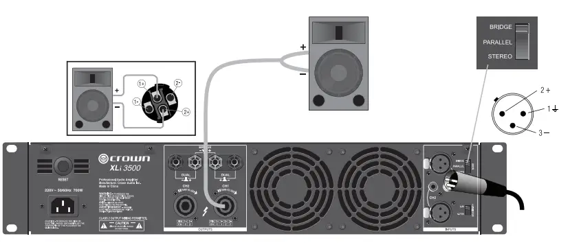
Bridge-Mono Wiring Using the Speakon® Connectors
Bridge-mono mode doubles the output power of the amplifier.
- See Figure 5. On the back panel, set the Output Mode Switch to BRIDGE.
- Wire the speaker to the Speakon® connector as shown.
- Only the Channel 1 Gain Control works in Bridge-mono mode.
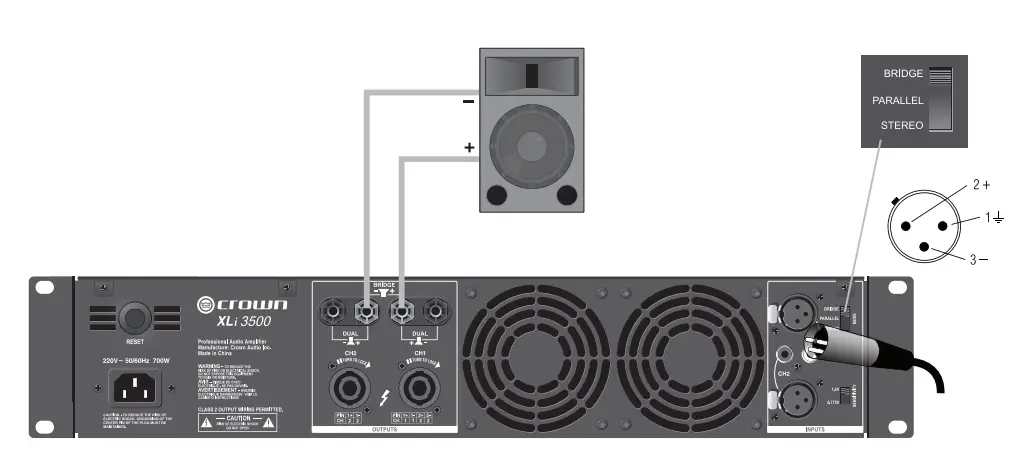
Bridge-Mono Wiring Using the Binding Post Connectors
Bridge-mono mode doubles the output power of the amplifier.
- See Figure 5. On the back panel, set the Output Mode Switch to BRIDGE.
- Wire the speaker to the binding post connectors as shown.
- Only the Channel 1 Gain Control works in Bridge-mono mode.
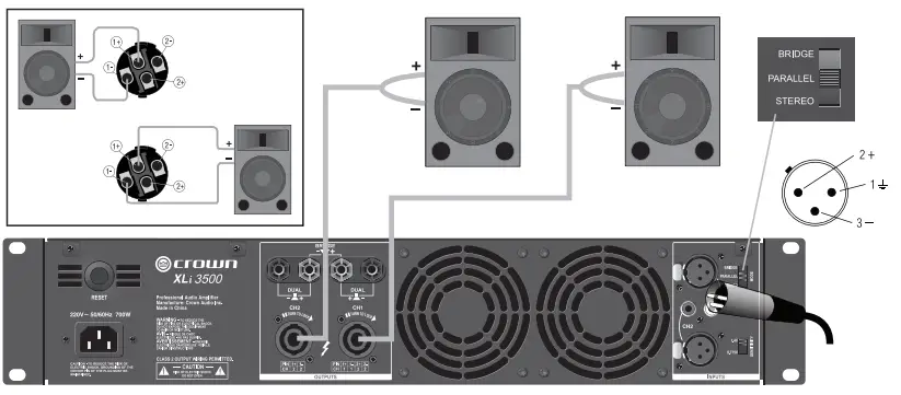
Parallel Wiring Using the Speakon® Connectors
With this wiring, a signal sent to one of the input connectors is paralleled to both channels so that it is reproduced by both speakers.
- See Figure 7. On the back panel, set the Output Mode Switch to PARALLEL.
- Wire the speakers to the Speakon® connectors as shown.
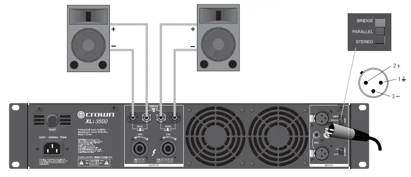
Parallel Wiring Using the Binding Post Connectors
With this wiring, a signal sent to one of the input connectors is paralleled to both channels so that it is reproduced by both speakers.
- See Figure 8. On the back panel, set the Output Mode Switch to PARALLEL.
- Wire the speakers to the binding post connectors as shown.
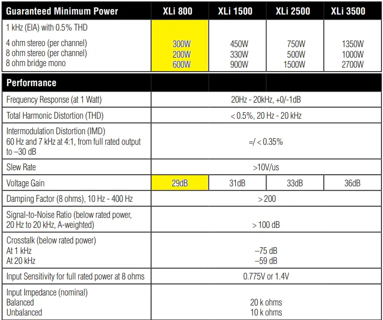
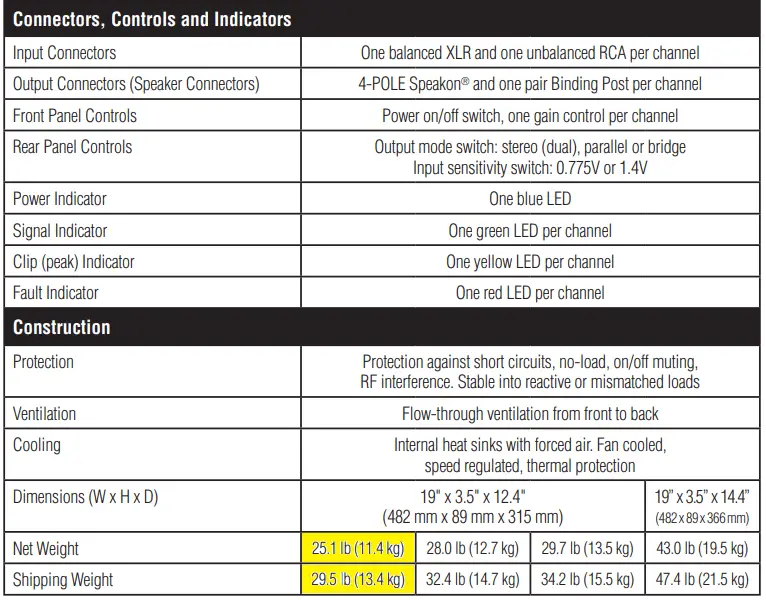
SPECIFICATIONS
WARRANTY
SUMMARY OF WARRANTY
Crown International, 1718 West Mishawaka Road, Elkhart, Indiana 46517-4095 U.S.A. warrants to you, the ORIGINAL PURCHASER and ANY SUBSEQUENT OWNER of each NEW Crown product, for a period of one (1) year from the date of purchase by the original purchaser (the “warranty period”) that the new Crown product is free of defects in materials and workmanship. We further warrant the new Crown product regardless of the reason for failure, except as excluded in this Warranty.
Warranty is only valid within the United States of America. For information on Warranty outside of the U.S.A, please contact your local distributor.
ITEMS EXCLUDED FROM THIS CROWN WARRANTY
This Crown Warranty is in effect only for failure of a new Crown product which occurred within the Warranty Period. It does not cover any product which has been damaged because of any intentional misuse, accident, negligence, or loss which is covered under any of your insurance contracts. This Crown Warranty also does not extend to the new Crown product if the serial number has been defaced, altered, or removed.
WHAT THE WARRANTOR WILL DO
We will remedy any defect, regardless of the reason for failure (except as excluded), by repair, replacement, or refund. We may not elect refund unless you agree, or unless we are unable to provide replacement, and repair is not practical or cannot be timely made. If a refund is elected, then you must make the defective or malfunctioning product available to us free and clear of all liens or other encumbrances. The refund will be equal to the actual purchase price, not including interest, insurance, closing costs, and other finance charges less a reasonable depreciation on the product from the date of original purchase. Warranty work can only be performed at our authorized service centers or at the factory. Warranty work for some products can only be performed at our factory. We will remedy the defect and ship the product from the service center or our factory within a reasonable time after receipt of the defective product at our authorized service center or our factory. All expenses in remedying the defect, including surface shipping costs in the United States, will be borne by us. (You must bear the expense of shipping the product between any foreign country and the port of entry in the United States including the return shipment, and all taxes, duties, and other customs fees for such foreign shipments.)
HOW TO OBTAIN WARRANTY SERVICE
You must notify us of your need for warranty service within the warranty period. All components must be shipped in a factory pack, which, if needed, may be obtained from us free of charge. Corrective action will be taken within a reasonable time of the date of receipt of the defective product by us or our authorized service center. If the repairs made by us or our authorized service center are not satisfactory, notify us or our authorized service center immediately.
DISCLAIMER OF CONSEQUENTIAL AND INCIDENTAL DAMAGES
YOU ARE NOT ENTITLED TO RECOVER FROM US ANY INCIDENTAL DAMAGES RESULTING FROM ANY DEFECT IN THE NEW CROWN PRODUCT. THIS INCLUDES ANY DAMAGE TO ANOTHER PRODUCT OR PRODUCTS RESULTING FROM SUCH A DEFECT. SOME STATES DO NOT ALLOW THE EXCLUSION OR LIMITATIONS OF INCIDENTAL OR CONSEQUENTIAL DAMAGES, SO THE ABOVE LIMITATION OR EXCLUSION MAY NOT APPLY TO YOU.
WARRANTY ALTERATIONS
No person has the authority to enlarge, amend, or modify this Crown Warranty. This Crown Warranty is not extended by the length of time which you are deprived of the use of the new Crown product. Repairs and replacement parts provided under the terms of this Crown Warranty shall carry only the unexpired portion of this Crown Warranty.
DESIGN CHANGES
We reserve the right to change the design of any product from time to time without notice and with no obligation to make corresponding changes in products previously manufactured.
LEGAL REMEDIES OF PURCHASER
THIS CROWN WARRANTY GIVES YOU SPECIFIC LEGAL RIGHTS, YOU MAY ALSO HAVE OTHER RIGHTS WHICH VARY FROM STATE TO STATE. No action to enforce this Crown Warranty shall be commenced after expiration of the warranty period.
THIS STATEMENT OF WARRANTY SUPERSEDES ANY OTHERS CONTAINED IN THIS MANUAL FOR CROWN PRODUCTS. 07/12
Frequently Asked Questions
Four speakers that are perfectly matched and a top-notch 2-channel amp make up the ultimate system. Find the positive and negative terminals of the amplifier. By observing the straightforward + and – signs, you may identify the model of an amplifier.
In an amplifier, a stereo pair of channels can be bridged into a single mono output channel. Bridging is widely utilised to increase the power of massive full-range speakers in a two-channel system or home theatre as well as larger passive in-room or in-wall subwoofer speakers.
You can, and it’s usually safe to do so. It is feasible to do this with a wide variety of guitar amplifier types, but it is doable with any guitar amplifier that has two primary inputs. However, you must proceed with caution because sending two signals through an amplifier with a high gain will damage the amplifier.
In a two-channel setup, there are in fact two (well explained) ways to connect a powered sub. Submit the speaker line from your amplifier to the speaker, and then use another set of speaker cables to connect your speakers.
Before being transferred to an external source, the audio signals from an audio source are amplified by a 2-channel amplifier. In addition to being frequently used in vehicular audio systems, it can be used in home theatre systems and other audio applications.
As many speakers as your amplifier can handle can be linked together. A two channel amplifier can have four speakers connected to it either in series or in parallel. The impedance levels and constraints of the amplifier and speakers together determine which one to choose.
Due to the likelihood that they will notice each other and frequently blow fuses, activate protection, or entirely blow up, two amps cannot be connected to a single set of speaker terminals.
A two-channel amplifier can be connected to six speakers either in series or in parallel. Which path you choose should depend on the speakers and amplifiers you have. The range and boundaries of their impedance should be taken into consideration.
A stereophonic audio-frequency amplifier, often driven by a single power source mounted on the same chassis, with two independent amplifiers for each of the two sound channels.
Start by connecting the positive terminal of the amplifier to the positive terminal of the first speaker. After that, connect the second speaker’s positive terminal to the first speaker’s negative terminal. Once a simple chain series of connections between all four speakers has been built, keep repeating this.
A two-channel amplifier can really power three speakers. To achieve this, wire two speakers in parallel or series, then connect the junction circuit to one side of the amplifier. The other side of the amplifier can then receive the last speaker.
Single-channel guitar amplifiers are great for pedal platform amplifiers even if they cannot be adjusted between different levels of distortion. The clean, crunch, and high-gain channels on guitar amplifiers with two channels, on the other hand, are all separate. As a result of being able to switch between different tones, a player becomes more adaptable.
Parallel and series connections are the only real ways to connect two speakers to a single amplifier. If the impedance of your speakers is 8 ohms or greater, you can usually connect them in parallel. If the total impedance of your speakers is less than 8 ohms, connect them in series.
Before being transferred to an external source, the audio signals from an audio source are amplified by a 2-channel amplifier. In addition to being frequently used in vehicular audio systems, it can be used in home theatre systems and other audio applications.
Series wiring will yield the best results when four speakers that are similar to one another are used. You must also validate that your 2-channel amp is of high calibre and is more than capable of concurrently driving all four speakers. First, connect the positive terminal of the amplifier to the positive terminal of the first speaker.


