CNX KC12 Mini PC
Safety Warning
To avoid the risk of fire, electric shock, and personal injury, basic safety precautions should be followed when using this computer, including the following:
- Read these guidance notes carefully before using the computer;
- Place this computer on a smooth countertop prior to setup;
- Keep the computer away from heat, humidity and dust;
- Do not hit or drop the computer to avoid damage;
- Do not spill any liquid on the computer to avoid damaging it or causing it to burn;
- Do not clog computer vents or other open slots;
- Unplug the computer if it will not be used for a long time;
- Do not disassemble the computer by For safety reasons, have it done by a professional.
Thanks for your support and happy using!
This product is not sold with a power adapter, if consumers use a power adapter to supply power, they should buy the supporting use of CCC certification and meet the requirements of the power adapter.
Product Specifications
| Processor Specifications | |||
| CPU | Intel Alder Lake Core i7-1270P I7-1280-P TDP:28W Intel Core i7-12700H I7-12900H TDP:45W | ||
| CPU Platform | Intel Alder Lake 12th gen CPU | ||
| Graphics Cards | Intel® Iris® Xe Graphics Support 4-display | ||
| Memory | |||
| Memory Type | DDR4 2133MHz/2400MHz/2666MHz/3200MHZ | ||
| Memory Slot | 2 × DDR4 SO-DIMM up to 64GB | ||
| Expansion Slots | |||
| Wifi Slot | 1×M.2 2230 slot(support WIFI/BT) WIFI:802.11 b/g/n/AC/AX Bluetooth 4.0 or above | ||
| SSD Slot | 1×M.2 2280 slot(support SATA/NVME Gen3 X4) 1×M.2 2280 slot(NVME PCIE GEN4 X4 ) | ||
| HDD | 1×SATA HDD 2.5inch (Available) | ||
| Front Panel | |||
| Power-on button | 1×Power Button | ||
| Thunderbolt | 1×Thunderbolt4(Compatible with PD power supply) | ||
| USB Interface | 4×USB3.2 Gen1 | ||
| Audio Interface | 1×3.5mm earphone 1×3.5mm MIC in | ||
| Rear Panel | |||
| Power port | |||
| 1×DC Jack 5.5*2.5mm (12-19V) | |||
| Lan slot | |||
| 2×RJ45 2500M | |||
| Display Interface | |||
| 2×HDMI Out 2.0 4K 60HZ 1×DP 1.4 1×Type-C Thunderbolt 4 | |||
| USB Slot | |||
| 2×USB2.0 | |||
| Other parameters | |||
| Dimension | 175×128×46mm | ||
| Power adapter | 12V-19V 90W ,Type-C support PD Battery charger,96W above | ||
| BIOS support | AMI UEFI BIOS,support PXE,WOL | ||
| Working Environment | Temperature: -10~50℃ Humidity: 5%~95% | ||
| Storage environment | Temperature: -20~80℃ Humidity: 5%~95% | ||
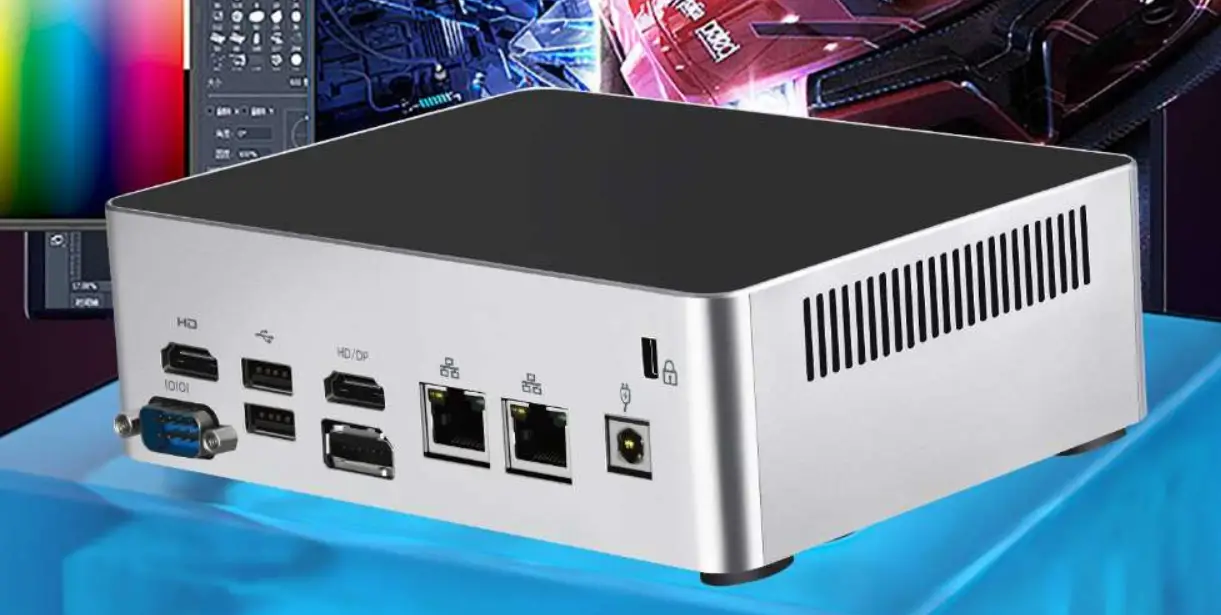
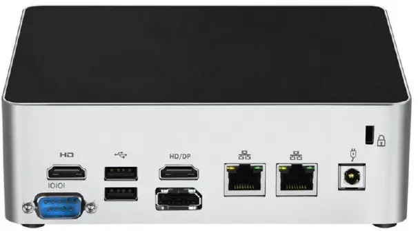
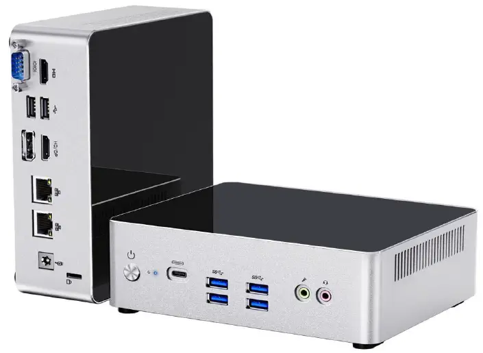
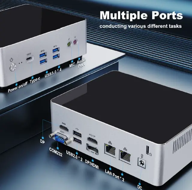
Interface Description
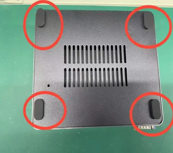
How to add RAM and replace SSD
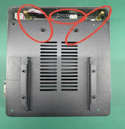
- To remove the bottom case, first remove the four foot cover.

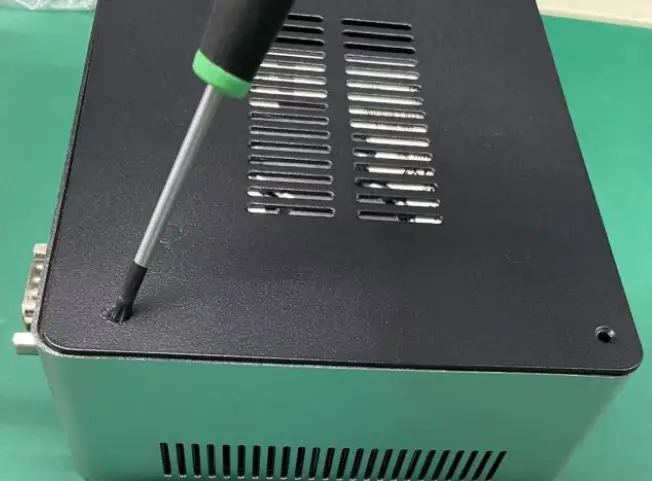
- Use a screwdriver to unscrew the screws to open the bottom case.

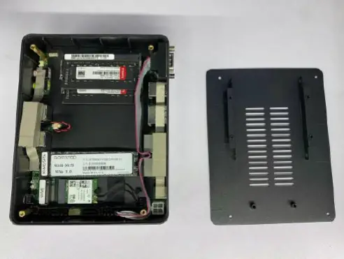
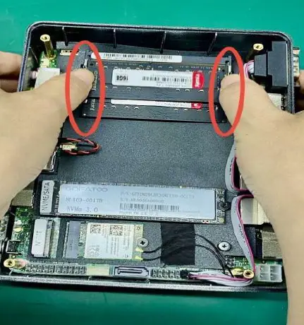
- After open the bottom case, you will see inside slot for RAM SSD and header on the motherboard

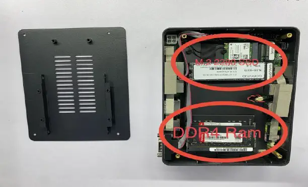
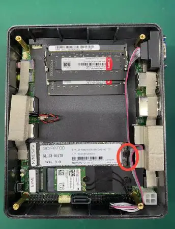
- The memory and SSD are installed in the locations shown in the photos. SSD support 2 slot for NVME/SSD & ONLY NVME SSD

- Adding or replacing memory.

- If you want to replace the SSD, please remove the screws first.

- when close the bottom case, please pay attention the direction as picture show

Attention
- The memory standard for this computer is SO-DIMM DDR4 and the SSD standard is M.2 2280 SSD.
- You can also add a 7mm 2.5″ hard drive to this computer.
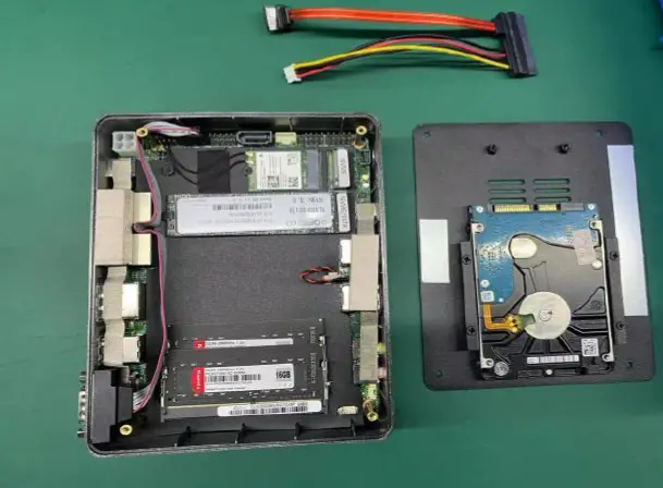
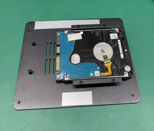
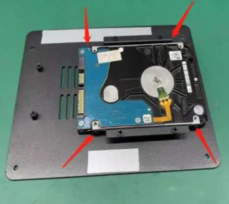
How to install a 2.5inch hard drive
- Hard drive size is 7mm 2.5 inches

- Align the drive with the bracket screw holes.

- Tighten the screws on both sides. (Four in total)

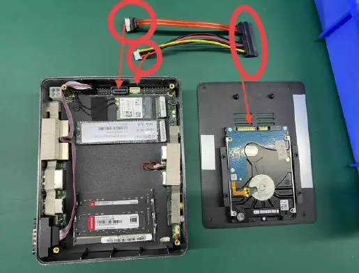
- Connect the hard drive to the motherboard connectors with the attached special SATA cable and SATA power cable.

BIOS Setup
BIOS Instruction
This motherboard uses AMI BIOS, which is known as Basic Input Output System(Basic input/output system). It is stored in a chip on the motherboard of your computer. When you turn on your computer, BIOS is the first program to run, and it has the following main functions:
- A. Power On Self Test (POST), the function is to check if the computer is good.
- B. Initialize and detect some external devices and load and run your operating system.
- C. Provides the lowest, most basic level of control over your computer hardware.
- D. Manage your computer through SETUP in BIOS.
BIOS data is stored in a CMOSRO RAM chip on the motherboard, maintained by a 3.3V coin cell battery, which contains important
information about the system and the setup program for setting system parameters – the BIOS Setup program. When the system is
running normally, the BIOS does not need to be modified, and when the CMOS data is lost due to other reasons, the BIOS needs to be reset.
Attention:
Improper BIOS settings can directly damage your computer’s hardware and even burn your motherboard, so it is recommended that those unfamiliar with the settings be careful to modify them. Due to the BIOS in the motherboard constantly upgraded, this manual in the relevant BIOS information for reference only. Therefore, the BIOS information in this manual is not guaranteed to be consistent with the information in the actual BIOS of the motherboard information.
BIOS Settings
Press F2 to enter BIOS Setup
Press F7 to enter the Boot menu
Press <Enter> to select and use Page Up and Page Down to change the options. Press <F1> for help, press <Esc> to exit. Please see the following sheet for details.
| Control Keys | Function Description |
| ←/→ | Move the left and right arrows to select the screen |
| ↑/↓ | Move the up and down arrows to select the up and down items |
| + / – | Increase/decrease the value or change the selection |
| <Enter> | Select this option to enter the sub-menu |
| <ESC> | Return to the main screen, or end the CMOS SETUP program from the main screen |
| <F1> | Show related auxiliary instructions |
| <F2> | Restore the previous setting |
| <F9> | Load the optimal value setting (BIOS initial value) |
| <F10> | Save the changed CMOS settings and reboot |
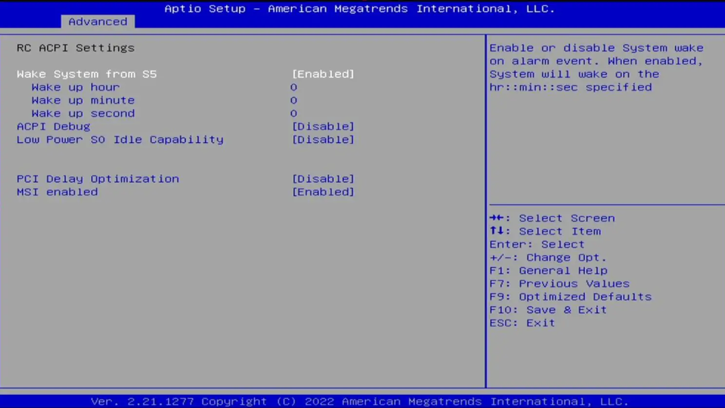
- Set the timer start time
Advanced→RC ACPI Setting→Wake system from S5(The default is Disabled)
After setting to Enabled, you can set the timer on time, which is hour, minute and second
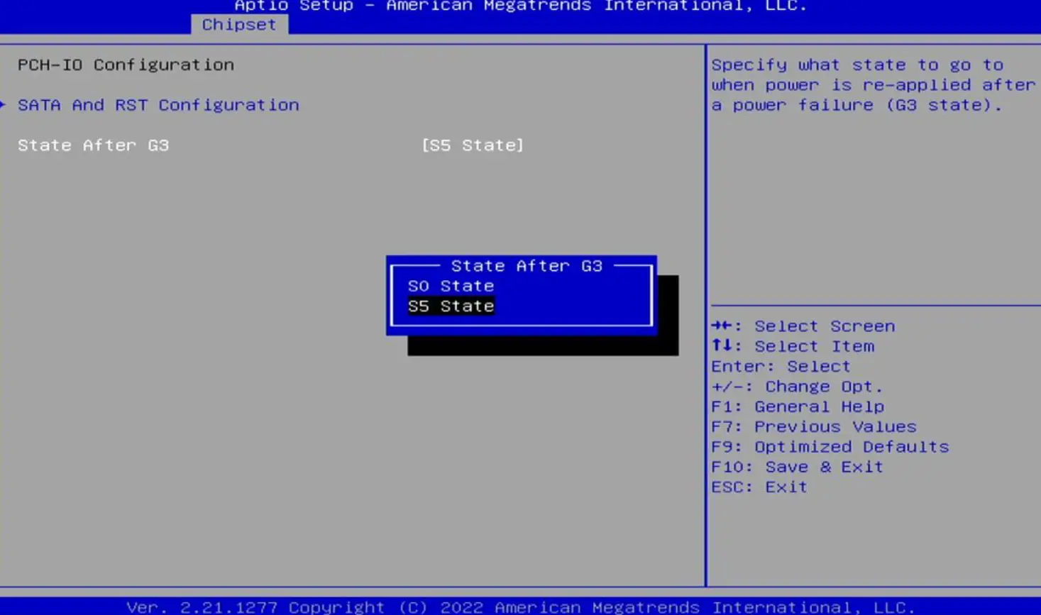
- Power-on settings(State After G3)
Chepset→PCH-IO Configuration →State After G3
- State After G3,The available options are:S0 State/S5 State
S5 State:Press the power on button to turn on normally
S0 State:Automatic power on after power on.
- State After G3,The available options are:S0 State/S5 State
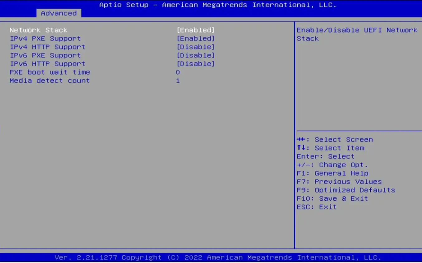
- PXE Setting(Network Stack Configuration)
Advanced→ Network Stack Configuration
- Network Stack The default option is Enabled
PXE Function Controller: Available options are: Enabled, Disabled
- Network Stack The default option is Enabled
How to avoid equipment failure
N0. | Failure phenomenon | Exclusion method |
| 1 | No power on |
|
| 2 | No screen display when computer is turned on |
|
| 3 | A black screen appears while the computer is running |
|
| 4 | Computer not responding |
|
| 5 | No sound from speakers or headphones |
|
If you encounter any questions in the use, please feel free to contact us, thanks again for your support and happy life!


