Remii 102735-XS Extra Slim 35 Inch Electric Fireplace User Manual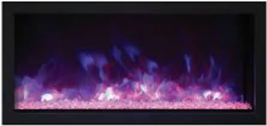
IMPORTANT INSTRUCTIONS
- Read all instructions before installing or using this heater.
- Keep combustible materials, such as furniture, pillows, bedding, papers, clothes and curtains at least 3 feet from the front of the heater; keep them away from sides and rear as well.
- Always unplug heater when its not in use.
- Do not operate the fireplace if it has a damaged cord or plug, after it has malfunctioned, or if the unit has been dropped or damaged in any way.
- Never place the heater where it may fall into a bathtub or other water containers.
- Do not run the cord under carpeting. Do not cover the cord with throw rugs, runners or anything else. Arrange the cord away from traffic areas where it could not be tripped over.
- To disconnect the heater, turn the controls to “OFF” before removing the plug from the outlet.
- Do not insert or allow foreign objects to enter any ventilation or exhaust opening, as this may cause an electric shock, fire or damage to the heater.
- To prevent a possible fire, do not block air intakes in any manner.
- A heater has hot and arcing or sparking parts inside. Do not use it in areas where gasoline, paint or flammable liquids are used or stored.
- Use this heater only as described in this manual. Any other use not recommended by the manufacturer may cause fire, electric shock or injury to persons.
- Avoid the use of an extension cord because the extension cord may overheat and cause a fire.
- Always use properly grounded fused and polarized outlets.
- Always use ground fault protection where it is required by electrical codes.
- Always disconnect the power before performing any cleaning, maintenance or relocation of the heater.
- To prevent a possible fire, do not burn wood or other materials in this heater.
- To prevent electric shock or fire, always use a certified electrician, should new circuits or outlets be required. When transporting or storing the heater, keep it in a dry place, free from excessive vibration
UNPACKING AND TESTING APPLIANCE
Carefully remove the appliance from the box. Prior to installing the appliance, test to make sure the appliance operates properly by plugging the power supply cord into a conveniently located 120 Volt grounded outlet.
GROUNDING APPLIANCE
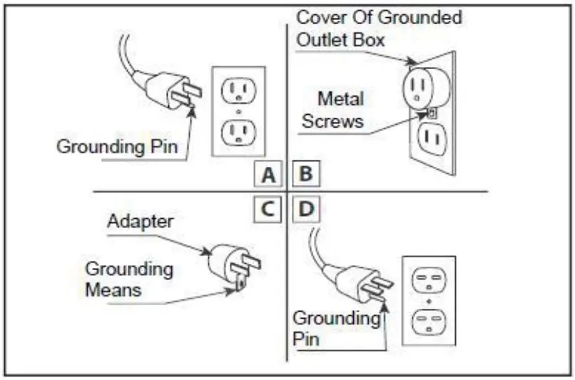
This appliance is for use on 120 Volts. The cord has a plug as shown in (A). An adapter as shown in (C) is available for connecting three-blade grounding type plugs to two-slot receptacles. The green grounding lug extending from the adapter must be connected to a permanent ground such as a properly grounded outlet box. The adapter should not be used if a three-slot grounded receptacle is available.
To disconnect appliance, turn controls to off, then remove plug from outlet.
LOCATING THE FIREPLACE Plan where to locate and frame the fireplace. This will save time and money later when you install the fireplace. Before installation consider the following:
- Where the fireplace is located must allow for wall and ceiling clearances (see INSTALLATION)
- Consider a location where the fireplace screen will not be exposed to direct sunlight from windows or doors.
- A 15 ampere, 120 Volt, 60 Hz branch circuit with proper ground must be available at the location.Preferably a dedicated branch circuit should be provided to avoid circuit breakers to trip of fuses to blow.
102735-XS
| Description | 102735-XS |
| Voltage | 120V AC 60Hz |
| Watts | 1465W Max |
| NO HEATER | 25W |
| MOTOR HEATER | 19W |
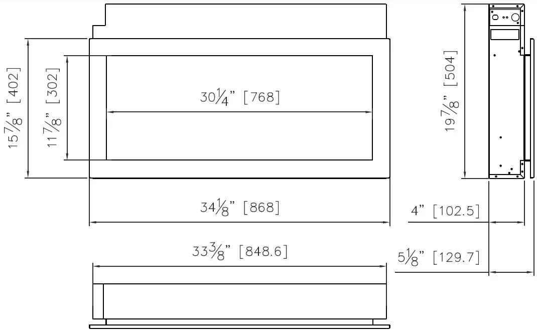
| Appliance Width | 34 1/8” or 99.5cm |
| Appliance Height | 19 7/8” or 50.4cm |
| Appliance Depth | 4” or 10.25cm |
| Gross Weight | 46.3 lbs or 21kgs |
| Plug Location | Left side |
| Cord Length | 70 7/8” or 180 cm |
| Rough Wall Opening Size | 34″ X 20 3/8″ or86.4 cm X 52 cm |
| BTU | 5000 |
This appliance has been tested in accordance with the UL Standard 2021 for fixed and location dedicated electric room appliances in the United States and Canada. If you need assistance during installation, please contact your local dealer.
NOTE: This appliance must be electrically wired and grounded in accordance with local codes. In the absence of local codes, use the current CSA C22.1 Canadian Electrical Code in Canada or the ANSI/NFPA 70 National Electrical Code in the United States
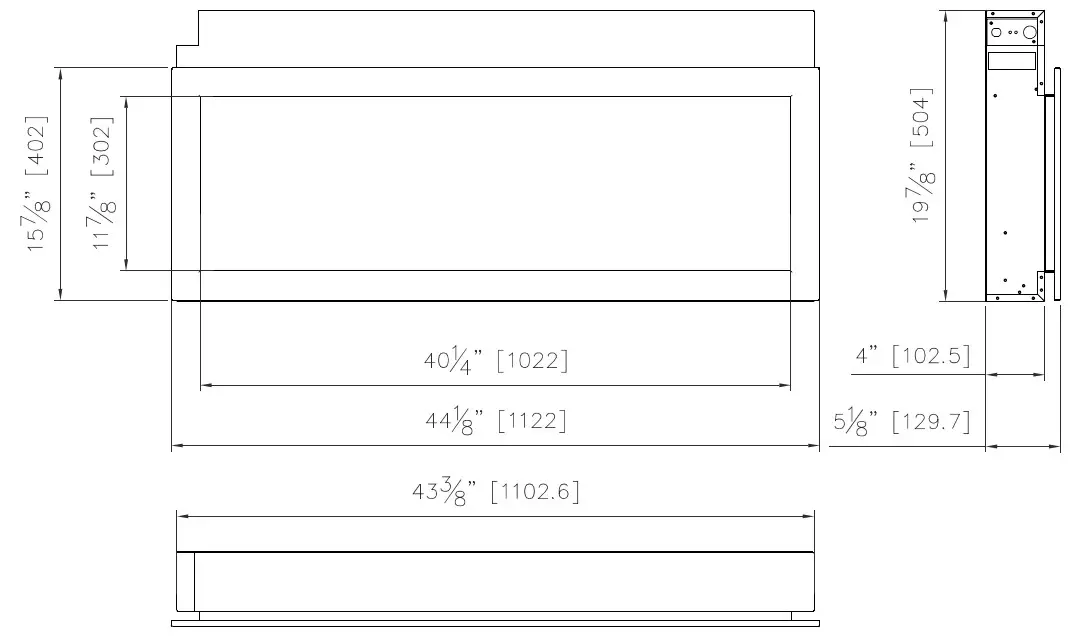
102745-XS
| Description | 102745-XS |
| Voltage | 120V AC 60Hz |
| Watts | 1465W Max |
| NO HEATER | 25W |
| MOTOR HEATER | 19W |
| Appliance Width | 44 1/8” or 99.5cm |
| Appliance Height | 19 7/8” or 50.4cm |
| Appliance Depth | 4”or 10.25cm |
| Gross Weight | 62 lbs or 28kgs |
| Plug Location | Left side |
| Cord Length | 70 7/8” or 180 cm |
| Rough Wall Opening Size | 44″ X 20 3/8″ or111.8 cm X 52 cm |
| BTU | 5000 |
This appliance has been tested in accordance with the UL Standard 2021 for fixed and location dedicated electric room appliances in the nited States and Canada. If you need assistance during installation, please contact your local dealer.
NOTE: This appliance must be electrically wired and grounded in accordance with local codes. In the absence of local codes, use the current CSA C22.1 Canadian Electrical Code in Canada or the ANSI/NFPA 70 National Electrical Code in the United States
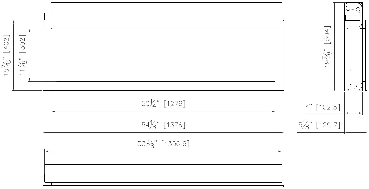
| Model Number | 102755-XS |
| Voltage | 120V AC 60Hz |
| Watts | 1465W Max |
| NO HEATER | 25W |
| MOTOR HEATER | 19W |
| Appliance Width | 54 1/8” or 137.6 cm |
| Appliance Height | 19 7/8” or 50.4 cm |
| Appliance Depth | 4 ” or 10.25 cm |
| Gross Weight | 86 lbs or 39kgs |
| Plug Location | Left side |
| Cord Length | 70 7/8” or 180 cm |
| Rough Wall Opening Size | 54″ X 20 3/8″ or137.2cm X 52 cm |
| BTU | 5000 |
This appliance has been tested in accordance with the UL Standard 2021 for fixed and location dedicated electric room appliances in the United States and Canada. If you need assistance during installation, please contact your local dealer.
NOTE: This appliance must be electrically wired and grounded in accordance with local codes. In the absence of local codes, use the current CSA C22.1 Canadian Electrical Code in Canada or the ANSI/NFPA 70 National Electrical Code in the United States.
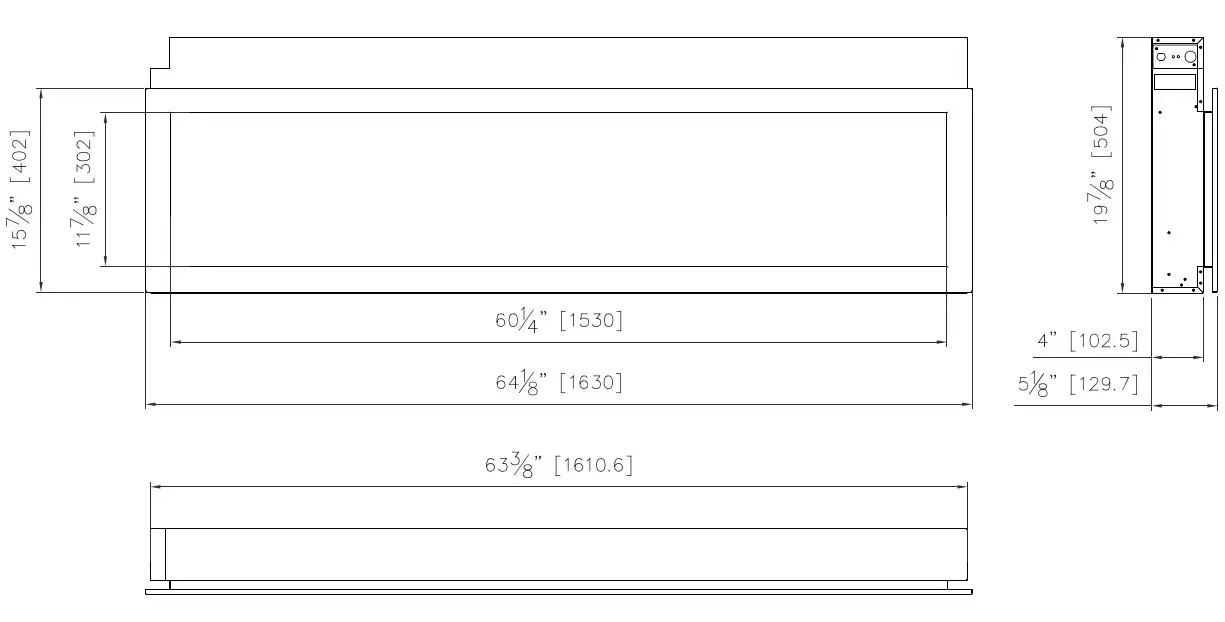
102765-XS
| Description | 102765-XS |
| Voltage | 120V AC 60Hz |
| Watts | 1465W Max |
| NO HEATER | 25W |
| MOTOR HEATER | 19W |
| Appliance Width | 64 1/8” or 163 cm |
| Appliance Height | 19 7/8” or 50.4 cm |
| Appliance Depth | 4” or 10.25 cm |
| Gross Weight | 108 lbs or 49 kgs |
| Plug Location | Left side |
| Cord Length | 70 7/8” or 180 cm |
| Rough Wall Opening Size | 64″ X 20 3/8″ or162.6cm X 52 cm |
| BTU | 5000 |
This appliance has been tested in accordance with the UL Standard 2021 for fixed and location dedicated electric room appliances in the United States and Canada. If you need assistance during installation, please contact your local dealer.
NOTE: This appliance must be electrically wired and grounded in accordance with local codes. In the absence of local codes, use the current CSA C22.1 Canadian Electrical Code in Canada or the ANSI/NFPA 70 National Electrical Code in the United States.
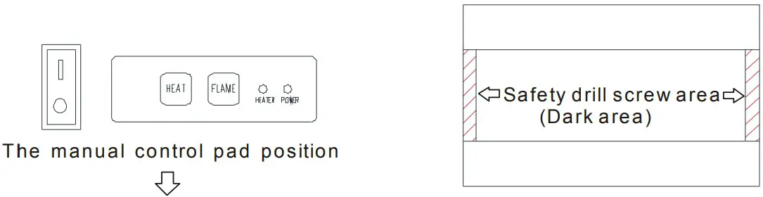
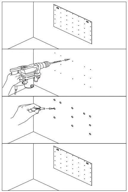
SAFETY DRILL SCREW AREA
There is a safety drill screw area as show below. Please make sure that the fix screws are in this area.
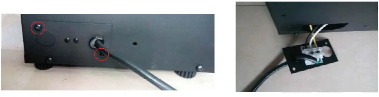
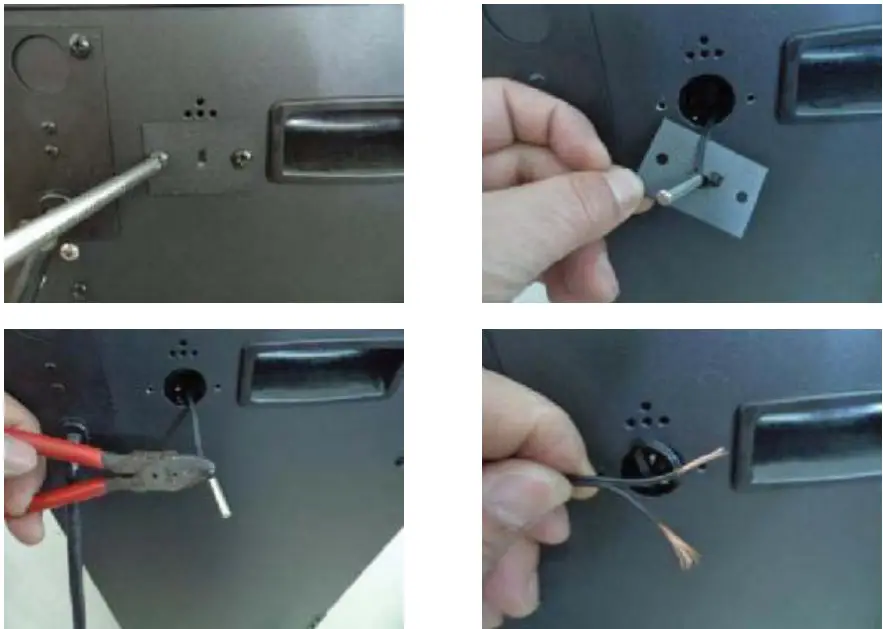
HARDWIRE INSTALLATION
Turn off the appliance completely and let cool before servicing. Only a qualified service person should service and repair this electric appliance. If it is necessary to hard wire this appliance, a qualified electrician must remove the cord connection, and wire the appliance directly to the household wiring. This appliance must be electrically connected and grounded in accordance with local codes, if hard wired. In the absence of local codes, use the current CSA C22.1 CANADIAN ELECTRICAL CODE in Canada or the current ANSI/NFPA 70 NATIONAL ELECTRICAL CODE in the United States.
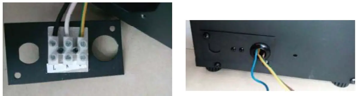
- Remove the cover plate from the left side of the appliance by removing the two screws, as shown below. Unscrew and remove power cord.

- Attach the wiring to the junction block. Please make sure the live wire goes into the L, the neutral wire into N and the ground wire into G.

- Put the plate back and screw back.
FOR BATHROOM USE
If the unit is installed in a bathroom it must be protected by a GIF receptacle or circuit. If receptacle is used it must be readily accessible. To prevent electric shock, please be aware that this unit is an electrical appliance that is NOT watertight and must be installed as to prevent water from entering unit. This must be installed away from showers, tubs, etc. Never locate fireplace where it may fall into a bathtub or other water container. All wiring connections to line power shall be in accordance with local building code requirements. Inquires about local codes and regulations must be done prior to installation.
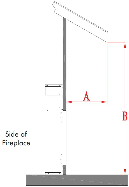
OUTDOOR INSTALLATIONS
The 102735-XS, 102745-XS, 102755-XS and 102765-XS electric fireplace are suitable for installation in outdoor areas protected from direct water impingement. In addition to maintaining the listed mantel and combustibles clearances, a rain protection overhang factor of 1/2 shall be constructed to the front and to each side of the installed appliance. See illustration below. All wiring connections to line power shall be in accordance with local building code requirements. Inquires about local codes and regulations must be done prior to installation.
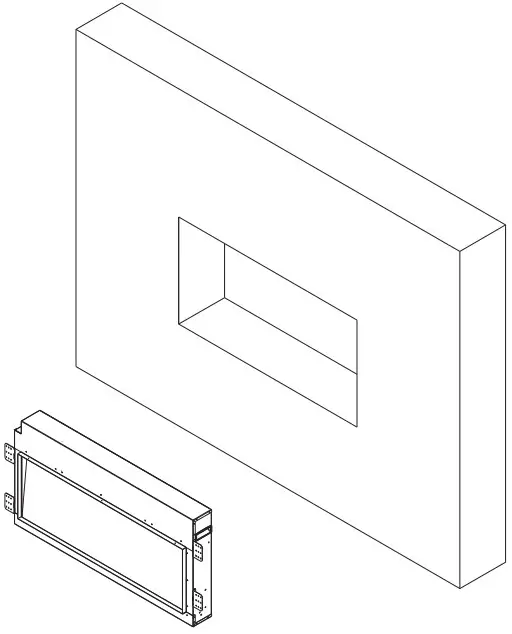
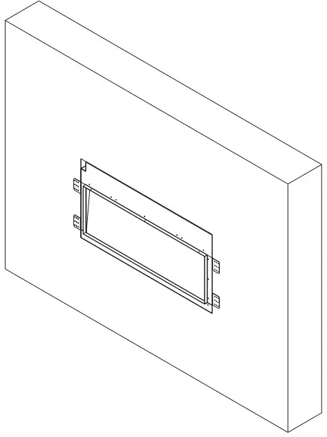
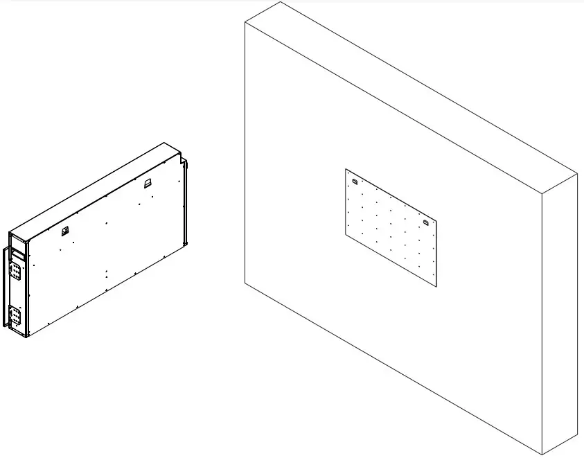
INSTALLATION
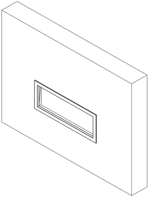
The 102735-XS, 102745-XS, 102755-XS and 102765-XS models are designed to be either built-in or wall-mounted depending on preference. These units allow for the finishing material (drywall, stone, tile, etc) to be built right down to the glass edge. However, that application is not always desirable or available so the surround could be used as an alternate finish option
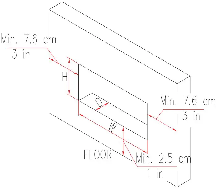
The rough wall opening size of the fireplace:
| W(“) | D(“) | H(“) | |
| 102735-XS | 34 | 4 1/2 | 20 3/8 |
| 102745-XS | 44 | 4 1/2 | 20 3/8 |
| 102755-XS | 54 | 4 1/2 | 20 3/8 |
| 102765-XS | 64 | 4 1/2 | 20 3/8 |
Built-in Installation Instructions

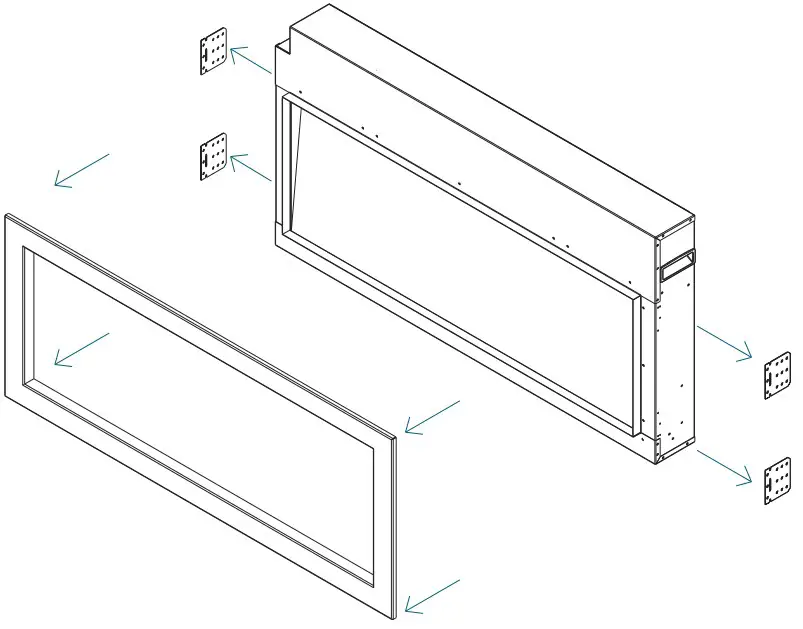
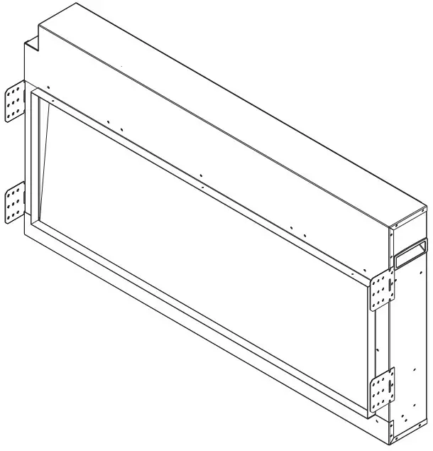
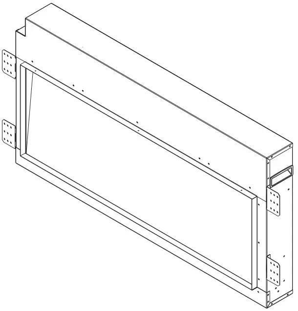
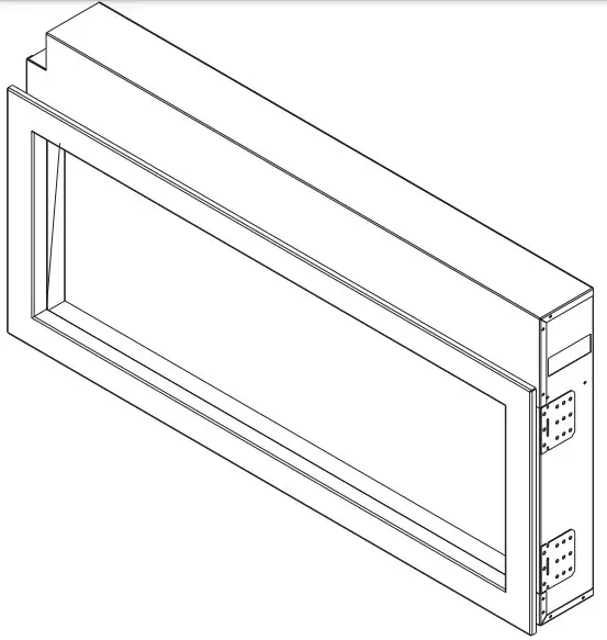
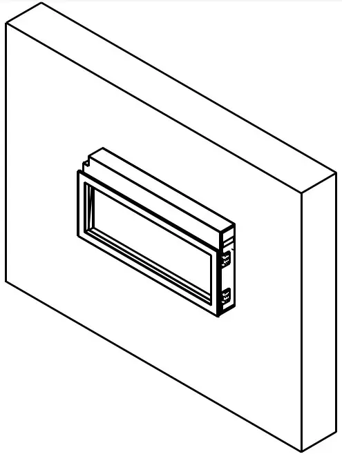
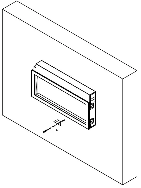
WALL MOUNT INSTALLATION INSTRUCTIONS
MEDIA OPTIONS
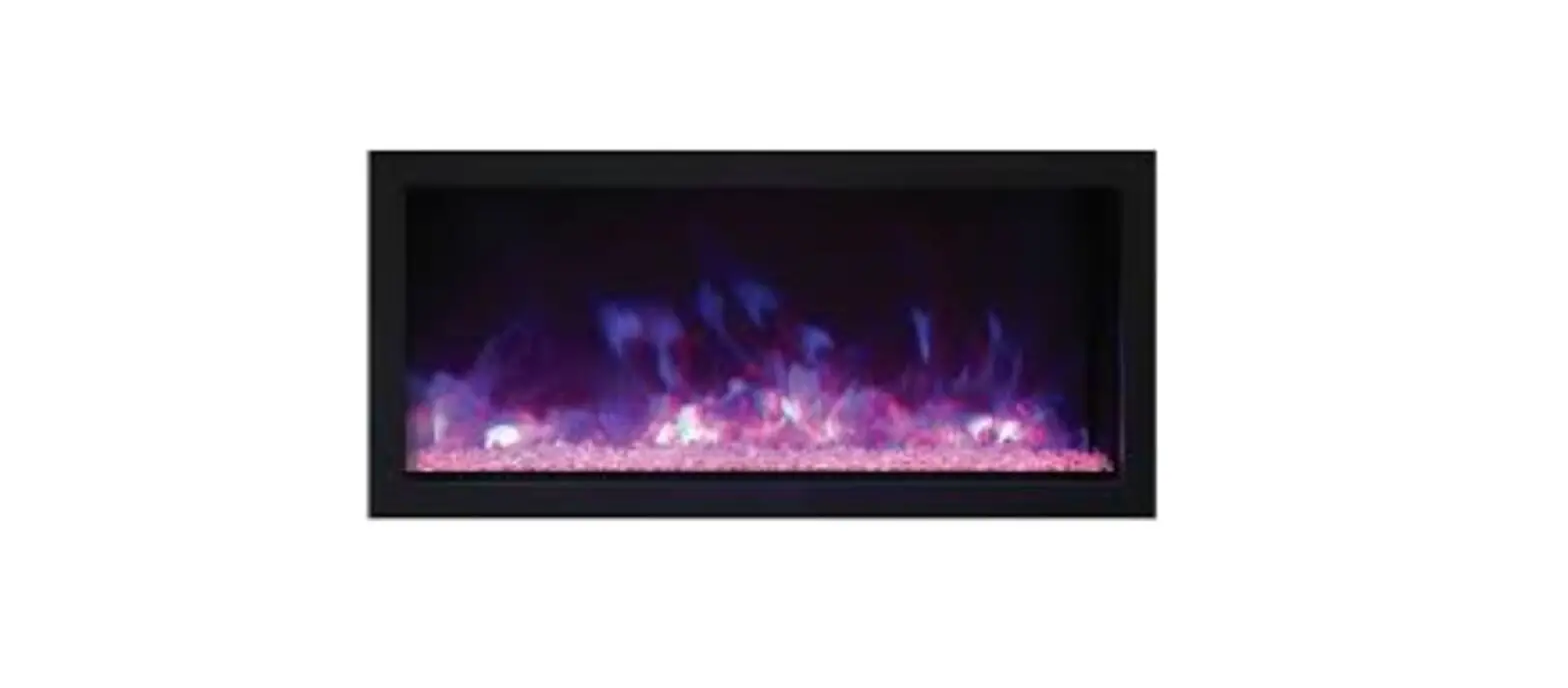
The 102735-XS, 102745-XS, 102755-XS and 102765-XS are shipped with two mixture media shows below: the Canyon brown and Ocean blue. Consumers may purchase optional decorative media if they choose. See dealer for more details.

INSTALLATION THE DECORATIVE MEDIA

OPERATION
The fireplace can be operated either by the switches located on the left bottom of the fireplace unit or by supplied remote control. Plug the fireplace into a 15 Amp wall socket.
MANUAL OPERATION
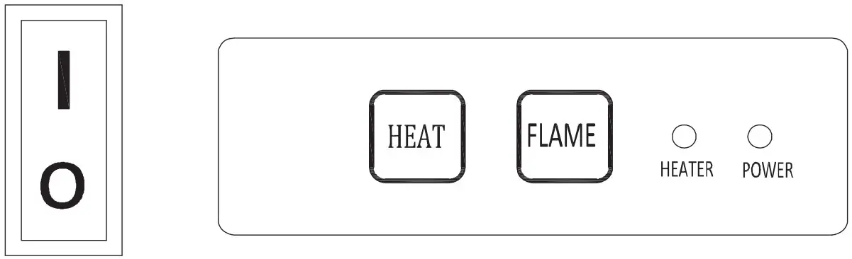
- The main power ON/OFF switch in position O, the fireplace is OFF.
- When main power ON/OFF switch is at position I, the fireplace is ready to use.
- Press the Heat button repeatedly to set the heater to desired heat setting. The heater indicator LED will glow which shows the current heater settings.
a) RED 1465W HEAT OUTPUT
b) BLUE 750W HEAT OUTPUT
c) PURPLE AUTO MODE
AUTO MODE
Under this mode the heater will automatically turn ON at high heat setting 1465W heat output when the room temperature drops below 22(72 ). When the room temperature is between 22-25(72-77) the heater output will switch to low heat setting 750W. When the room temperature goes above 25(77) the heater will be turned off and the cycle will continue. The LED indicator will be PURPLE in colour under this mode. Flame effect: Press the button marked Flame to adjust the flame brightness. The flame brightness will cycle through Low-Medium-High -OFF.
NOTE: If operated at the Low heat setting, the fireplace will not provide as much heat output as in the High heat setting, however the low setting will not require as much electrical power to operate. To avoid overloading a circuit, do not plug the fireplace into a circuit that already has other appliances working. When the fireplace is not in use switch off and unplug
SAFETY CUT-OFF
- This appliance is fitted with a safety cut-off which will operate if the fireplace overheats (eg. Due to blocked air vents). For safety reasons, the fireplace will NOT automatically reset.
- To reset the appliance, disconnect the appliance from the main supply for at least 10 minutes. Reconnect the supply to the main and switch on the appliance
REMOTE CONTROL OPERATION
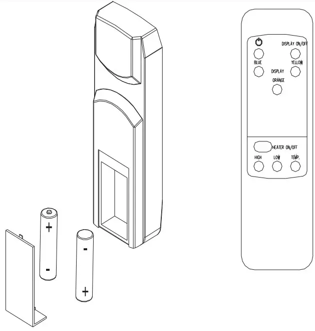
For remote to function make sure the heater is plugged in and main power switchlocated on the bottom left hand side is at position I. When operating the remote make sure you point the remote to the centre of the fireplace and make sure each time you press the button the buzzer inside the unit will bee p once. It takes some time for the receiver to respond to the transmitter. Do not PRESS the buttons more than once within twoseconds for correct operation. Power on button: The power-on button at top left corner of the remote is the main ON/OFF power button. This will turn off all the functions and the fireplace will be in standby mode.
DISPLAY ON/OFF button: Switching the fireplace flame and tray light ON/OFF. It has functions of setting memory.
DISPLAY BLUE button: Adjust the blue color brightness of flame and tray.
DISPLAY YELLOW button: Adjust the yellow color brightness of flame and tray.
DISPLAY ORANGE button: Adjust the orange color brightness of flame and tray.
HEATER ON/OFF button: Switching the heater ON/OFF. It has functions of setting memory.
HIGHT button: Press the high button to switch the heater to high heat setting 1465W.
LOW button: Press the low button to switch the heater to low heat setting 750W.
TEMP. button: Press the TEMP. button to switch the heater to AUTO mode. Under this mode the heater will operate in similar way as explained above for the manual operation.
INSTALLING WALL THERMOSTAT
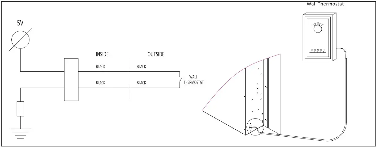
Wire the wall thermostat prior to installing the fireplace. WALL THERMOSTAT WIRING(24 VAC) Install Wall Thermostat per instructions provided with kit and per the following information:
- Turn off circuit breaker.
- Remove cover plate located on the left side of appliance.
- Pull the wire out and cut the inside thermostat. Connect the wires to the wall thermostat as shown below. Follow instructions provided with wall switch kit
REPLACEMENT PARTS
| NO | PART NUMBER | DESCRIPTION | QTY. | |||
| 102735-XS | 102745-XS | 102755-XS | 102765-XS | |||
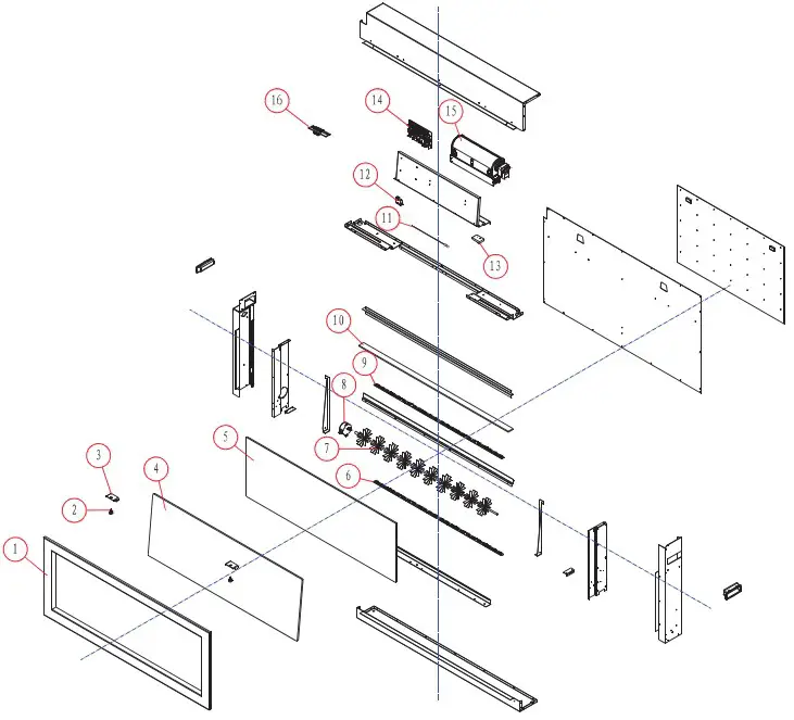
| 1 | 3148501 | 3134501 | 3136501 | 3138501 | TRIM | 1 |
| 2 | 10201505 | ADJUSTABLE SCREW | 2 | |||
| 3 | 3133009 | FRONT GLASS BRACKET | 2 | |||
| 4 | 10701274 | 10701249 | 10701251 | 10701253 | FRONT GLASS | 1 |
| 5 | 10702198 | 10702183 | 10702185 | 10702187 | FLAME EFFECT GLASS | 1 |
| 6 | 601139B | LED LIGHT(LED3-23-2) FOR TRAY | 0 / 1 / 2 / 0 | |||
| 6 | 601140B | LED LIGHT(LED3-33-2) FOR TRAY | 2 / 2 / 2 / 4 | |||
| 7 | 3148504 | 3134504 | 3136504 | 3138504 | FLICKER ASSEMBLY | 1 |
| 8 | 10101225 | FLICKER MOTOR | 1 | |||
| 6 | 601139B | LED LIGHT(LED3-23-2)FOR FLAME | 0 / 1 / 2 / 0 | |||
| 6 | 601140B | LED LIGHT(LED3-33-2)FOR FLAME | 2 / 2 / 2 / 4 | |||
| 10 | 10702202 | 10702177 | 10702179 | 10702181 | BOTTON GLASS | 1 |
| 11 | 10114001B | TEMPERATURE SENSOR | 1 | |||
| 12 | 10104002 | SWITCH | 1 | |||
| 13 | 301506 | REMOTE RECEIVER | 1 | |||
| 14 | 601097B | CIRCUIT BOARD(LRC16-03) | 1 | |||
| 15 | 602082B | BLOWER AND HEATER ASSEMBLY(FRT45-240) | 1 | |||
| 16 | 601032B | CONTROL PANEL | 1 | |||
| 10105064 | REMOTE | Not shown | ||||
EXPLODED VIEW
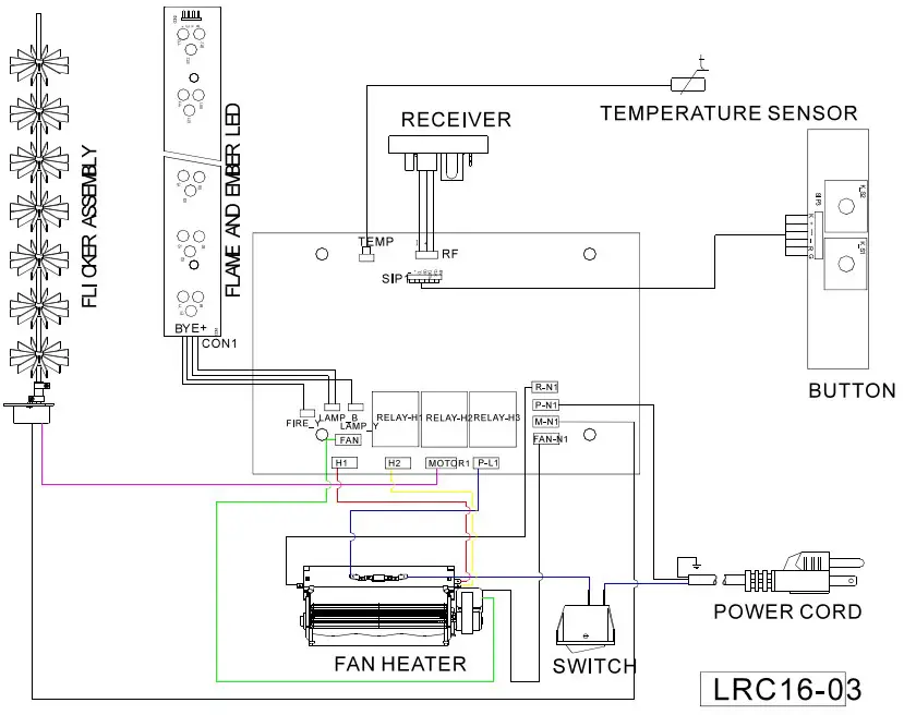
Wiring diagram
TROUBLE SHOOTING
| PROBLEM | POSSIBLE CAUSE | SOLUTION | ||||
| Dim or no flame | Flame LED’s are burnt out | Inspect the LED’s and replace them ifnecessary. | ||||
| Ember bed is notglowing or dimming | Ember LED’s are burnt out | Inspect the ember bed LED’s andreplace them if necessary. | ||||
| Appliance turns off and will not turn on | Appliance has overheated and safety device has caused thethermal switch to disconnect | Turn off the main switch, allow appliance to cool for 10 minutes, thenturn it on. | ||||
| Housetripped | circuit | breaker | has | Reset house circuit breaker. | ||
| Appliance’s fuse has blown | Replace the fuse. | |||||
| Appliance will not come on when switch is flipped to ON | Appliance is not plugged into an electrical outlet | Check plug and plug in. | ||||
| Appliance has overheated and safety device has caused thethermal switch to disconnect | Turn off the main switch, allow appliance to cool for 10 minutes, thenturn it on. | |||||
| Circuit board is burnt out | Inspect the circuit board and replaceit if necessary. | |||||
| No warm air coming outof appliance | Heater is burnt out | Inspect the burner and heaterassembly and replace it if necessary. | ||||
| Flame sputters | Flame motor is defective. | Call a qualified service technician andreplace flame motor. | ||||
| Remote Control does not work. | Low batteries.Unit switch in “O” position. | Replace AAA batteries in control.Turn the switch in “I” position. | remote | |||
| Flame is fixed. | Wiring may be loose or theflame motor may be defective. | |||||
SERVICE HISTORY
This heater must be serviced annually depending on usage.
| Date | DealerName | Service technicianName | Service Performed | Special Concerns |


