WAGO 787 Power supply
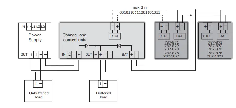
The battery module together with the UPS charge and control device 787-870, 787-875 or 787-1675 are used to create an uninterruptible 24 V power supply.
New features with the introduction of these intelligent battery modules:(with “battery control”):
- Automatic detection of connected battery module
- Reliable early warning signal when battery life expectancy is declining
- Extended life expectancy through temperature controlled battery management
Changing the batteries
It is not necessary to switch off the UPS charge- and control unit to change the batteries. The following procedures are recommended on battery modules:
- Remove all connectors and fuses
- Open the housing and disconnect the battery wiring
- Change both batteries
- Reconnect wiring and close housing
- Insert all connectors and fuses
Now connect the charge- and control unit together with the battery module to the 24V DC supply voltage.
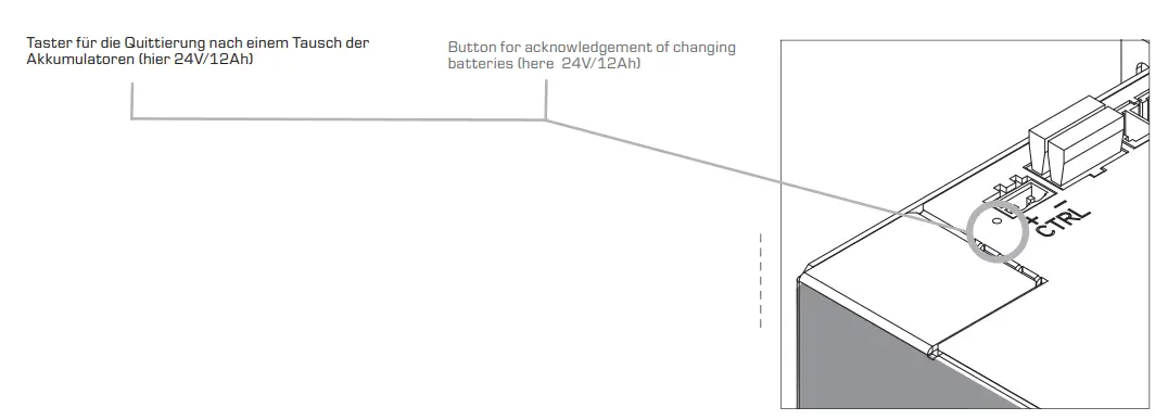
The battery change must be acknow-ledged at the battery module.
To do this push the reset-button during operation for 5 seconds (it is at the side of the terminals for both control lines). It can be accessed e.g. with a small ball pen refill. The charge- and control unit will signal the acknowledgment.
Safety measures before installation
This equipment is to be protected against improper use. Components
are not to be bent or isolation spacing changed, especially through handling and transport. The contact with electrical components and terminals
is to be avoided. Always disconnect the equipment from the mains supply, before commencing installation or wiring. The product descriptions, technical information in our main catalogue and the marking on the equipment ratings plate are to be observed. A sufficient aeration and ventilation of the location of the battery module must be ensured.
- The rechargeable batteries may only be disposed of when fully discharged and in acc. with the valid regulations. Installation
- The device may only be installed and put into operation by qualified personnel. The corresponding national regulations (e.g. VDE, DIN) must be observed.
- The VDE 0510 regulations regarding storage, installation and operation of the rechargeable battery module must be observed. No required min spacing must be observed to neighbouring components. Battery modules should be connected low-resistively and in a cool place (in cubicles usually at the lower end). The arrow (see dimensions) shows the direction of installed batteries. Overhead installation ist not allowed, all other mounting positions are possible!
- Do connect the supplied terminals after installation is finished. During longer downtimes it is recommended to pull off the fuse. To guarantee buffer operation, it is essential toexchange always both batteries regularly according to its specified lifespan. When replacing rechargeable batteries, please note that only two rechargeable batteries from the same batch may be used together.
The device will adjust the optimal charge-voltage and charge-current to provide optimal operation conditions for the battery. It is recommended to connect the control lines for an optimal battery management. Observe the correct polarity! If several batteries are connected in parallel, both control lines should be connected to only one of the batteries.
In case of non-use of the installations
( BAT > 3,5Ah max. 1 month / BAT < 3,5Ah max. 1 week) the fuses must be pulled on the assembled battery module.
Notice: Discharged batteries must be recharged as soon as possible, otherwise they may be damaged.
Connection
WARNING: To reduce the risk of mistaking the terminals, the supplied terminals must be used. If several batteries are connected in parallel, the control lines should be connected to only one of the batteries
- Introduction of intelligent battery modules
- internal fuses 2x25A at 24V/7Ah … 12Ah

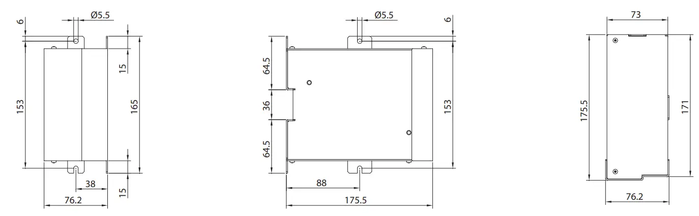
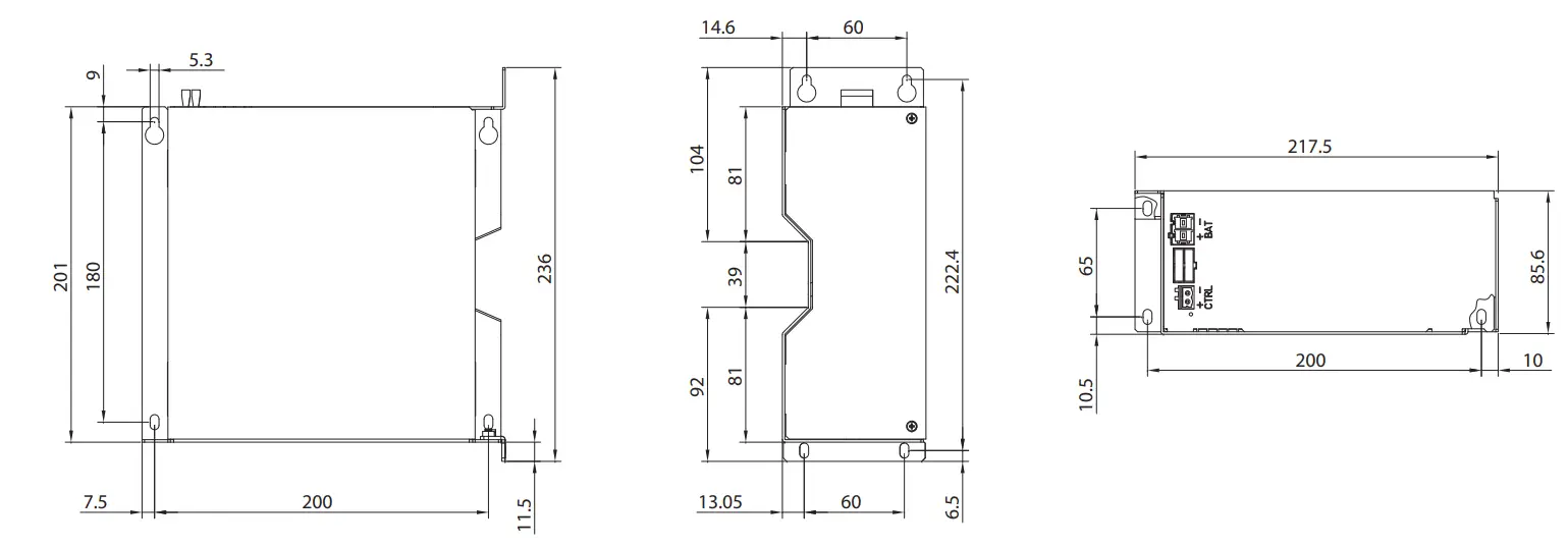
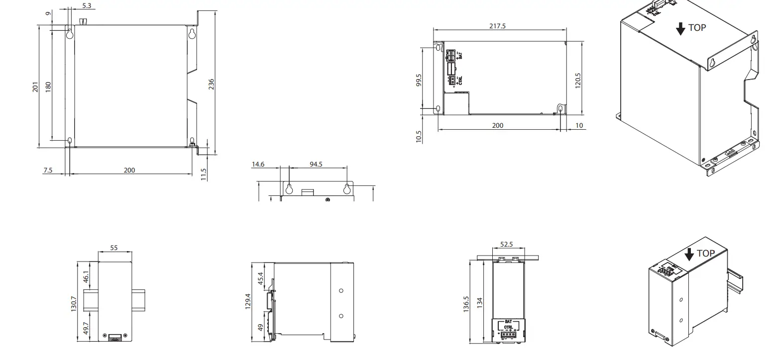
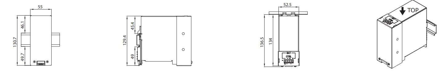
Maße (in mm) Dimensions (in mm)
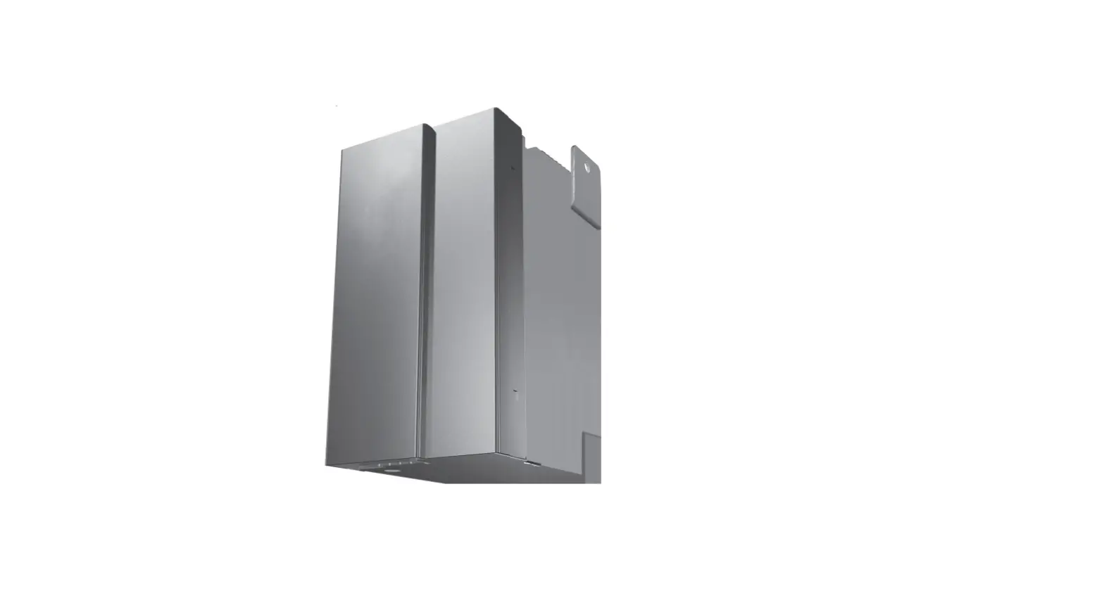
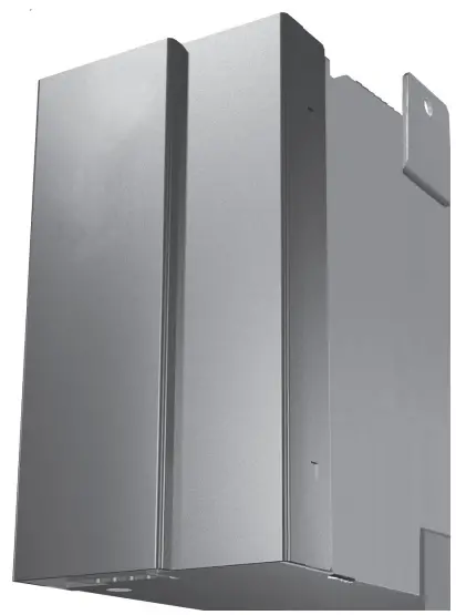
- Abbildung zeigt den 787-1671 This figure shows the 787-1681

- Abbildung zeigt den 787-871 This figure shows the 787-871

Technical data
| Technical data | 787-1671 | 787-876 | 787-871 | 787-872 | 787-873 | |
| Akkumodule, bestehend aus zwei Bleivlies-Akkumulatoren zur Verwendung mit einer USV Lade- und Kontrolleinheit maintenance-free AGM rechargeable batteries for use with a UPS charge and control device | ||||||
| Normen Standards | ||||||
| UL | in Vorbereitung pending | UL 508 listed | ||||
| Eingangsdaten Input data | ||||||
| Nominal input voltage | 24 Vdc | |||||
| capacity | 0,8 Ah | 1.2 Ah | 3.2 Ah | 7 Ah | 12 Ah | |
| Recommended max. charging current | 0,2 A | 0.3 A | 0.8 A | 1.8 A | 3 A | |
| Recommended end-of-charging voltage (at 25° C) | 27 Vdc | |||||
| Ausgangsdaten Output data | ||||||
| Nominal output voltage | 24 Vdc | |||||
| Nominal output current | 5 A | 7.5 A | 20 A | 40 A | ||
| internal fuse (type FK2) | 10 AT (Mini) | 15 AT | 25 AT | 2 x 25 AT | ||
| Connection in parallel | Ja Yes | |||||
| Umwelt Environment | ||||||
| For installation in Pollution Degree 2 environment | o o | |||||
| °C verwenden Use Copper Conductors only, rated 75 °C | o o | |||||
| Umgebungstemperatur Ambient temperature | -15° C … +40° C | |||||
| beim Entladen Ambient temperature discharge | -20° C … +40° C | |||||
| Storage temperature | -20° C … +40° C | |||||
| Lebensdauer Service life | 5 Jahre bei 20° C, 4 Jahre bei 30° C, 2 Jahre bei 40° C 5 years at 20° C, 4 years at 30° C, 2 years at 40° C | |||||
| späteste Inbetriebnahme Latest startup date | 6 Monate bei 30 … 40° C 6 months at 30 … 40° C | |||||
| Selbstentladung Self discharge | 3% / Monat bei 20°C 3% / month at 20°C | |||||
| Typ Akkumulator (2 Stück/Modul) Rechargeable battery type (2 pcs./module) | YUASA, NP0.8-12 Alternative: YUASA, Y0.8-12 Sun Battery MB12-0.8 | YUASA, NP1.2-12 Alternative: PANASONIC, LC-R121R3PG Sun Battery SB12-1.2 | YUASA, NP3.2-12 Alternative: PANASONIC, LC-R123R4PG Sun Battery SB12-3.4 | YUASA, NP7-12 Alternative: LC-R127R2PG1 Sun Battery SB12-7.2L | YUASA, NP12-12 Alternative: PANASONIC, LC-RA1212PG1 Sun Battery SB12-12L | |
| Sicherheit und Schutz Safety and protection | ||||||
| Schutzart Protection index | IP 20 | |||||
| Schutzklasse Safety class | III | |||||
| Überspannungskategorie Overvoltage category | I | |||||
| Anschluss und Montage Terminals and Mounting | ||||||
| Ein/Ausgang (WAGO Multisteckersystem) Input/Output (WAGO multi plug system) | Serie 721, max. 2,5 mm2 Series 721, max. 2.5 mm2 | Serie 231, max. 2.5 mm2 Series 231, max 2.5 mm2 | Serie 831, max. 10 mm2 * Series 831, max 10 mm2 * | |||
| Battery control (WAGO Multisteckersystem) Battery-Control (WAGO multi plug system) | Serie 231, max 2,5 mm2 (max. Leitungslänge 3 m) Series 231, max 2.5 mm2 (max. wire length 3 m) | |||||
| Befestigung Mounting | TH35-Schienenmontage mounting on DIN 35 mm rails | Direktverschraubung direct screw mounting | ||||
| Maße und Gewichte Dimension and weights | ||||||
| Gewicht (exkl. Verpackung) weights without packaging | 1.0 kg | 1.8 kg | 4 kg | 7.1 kg | 10.5 kg | |
| Maße B x H x T ** Dimensions width x height x depth** | 72 x 97 x 107 mm | 55 x 131 x 136.5 mm | 76.2 x 165 x 175.5 mm | 217.5 x 236 x 86 mm | 217.5 x 236 x 120.5 mm | |
| Bestellnummer Order no. | ||||||
| Standard Standard | 787-1671 | 787-876 | 787-871 | 787-872 | 787-873 | |
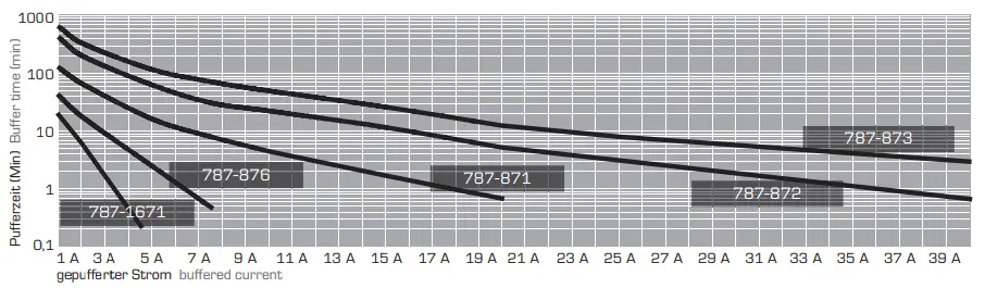
Buffer times dependet upon output current
- WAGO Series 831: With ferrule max. 6 mm2. Please use suitable anti-splaying method for fi ne-stranded conductors.
- Dimensions without terminals, depth T from upper edge of DIN rai
Wiring
- This figure shows the 787-872
- This figure shows the 787-873

- This figure shows the 787-786

ADDRESS: WAGO GmbH & Co. KG Hansastr. 27 32423 Minden
Germany
Phone: +49 571-887-0
Fax: +49 571-887-169
[email protected]


