
PROGRESS LIGHTING P300454-030-30 Everlume Close to Ceiling Instruction Manual
PACKAGE CONTENTS
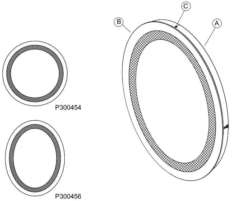
| PART | DESCRIPTION | QUANTITY |
| A | MirrorFrame | 1 |
| B | MirrorFace | 1 |
| C | Screws | 4 |
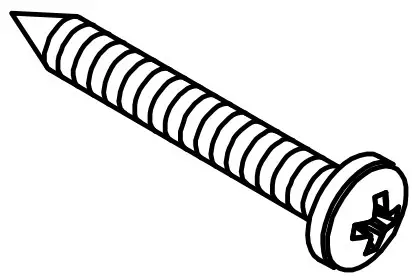
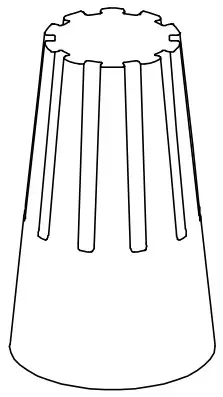
HARDWARE CONTENTS (not actual size)
- AA Pan Head Self Tapping Screw Qty: 4

- BB Wall Anchors Qty: 4

- CC Wire Nut Qty: 3


Safety Information
Please read and understand this entire manual before attempting to assemble, operate or install the product.
CAUTION: Read instructions carefully and turn electricity off at main circuit breaker panel before beginning installation.
CAUTION: Risk of fire. Min. 90°C supply conductors. Consult a qualified electrician to ensure correct branch circuit conductor.
WARNING: If any Special Control Devices are used with this fixture, follow instructions carefully to assure full compliance with N.E.C. requirements. If there are any questions, contact a qualified electrical contractor.
CAUTION: All glass is fragile. Use care when handling glass shades and bulbs.
THIS PRODUCT MUST BE INSTALLED BY A PERSON FAMILIAR WITH THE CONSTRUCTION AND OPERATION OF THE PRODUCT AND THE HAZARDS INVOLVED, IN ACCORDANCE WITH THE APPLICABLE INSTALLATION CODE. KEEP THESE INSTALLATION INSTRUCTIONS.
Preparation
- Before beginning installation, make sure all parts are included using the contents diagrams. If any part is missing or damaged, do not attempt to assemble, install or operate the product.
- Estimated assembly time: 30 minutes.
- Tools required for assembly (not included): screwdriver, pliers, wire stripper, safety glasses, electrical tape, ladder, drill.
Care and Maintenance
Shut off main power supply before cleaning product or changing light bulbs. To clean, wipe with damp cloth. Do not use abrasive cleaners or cleaners that contain alcohol.
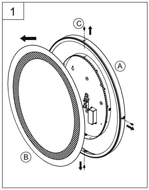
Assembly Instructions
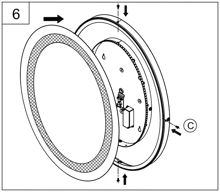
- Remove the 4 screws (C) around the edge of the mirror frame (A) and remove mirror face (B).

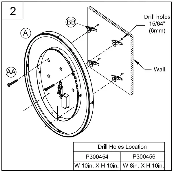
- Place the mirror frame (A) against the wall and mark the position of the screw holes through the mirror frame (A) on the wall. Ensurethat the mirror frame (A) is level.
Use a 15/64 inch drill bit to drill pilot holes at the locations marked and insert the wall anchors (BB).
Screw all but 1/8 inch length of the top two pan head self tapping screws (AA) into the top two wall anchors (BB).
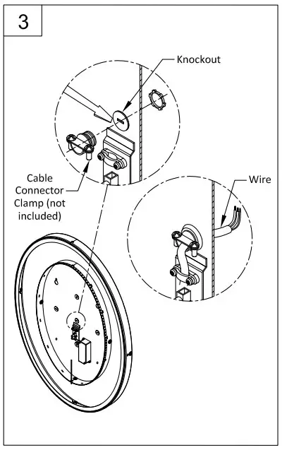
- Remove the knockout in the back of the mirror (A) located over the junction box.
Install a NM cable connector clamp (not included) into the knockout hole.
Pass the mirror jumper wire through the clamp and secure.
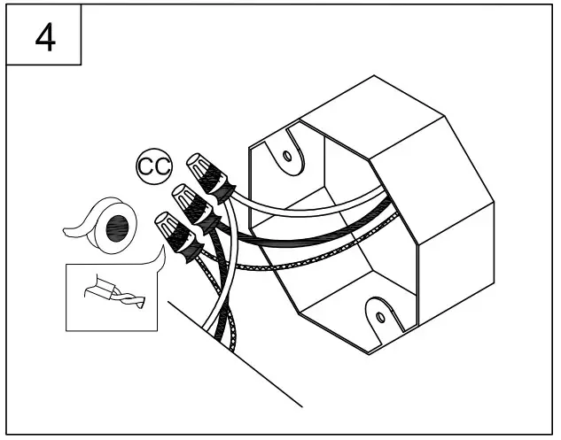
- Strip 3/8” of insulation from the electrical wire ends. Using wire nuts (CC), connect the WHITE fixture wire to the WHITE supply wire from the outlet box; connect the BLACK fixture wire to the BLACK supply wire from the outlet box.
Connect the fixture ground wire and supply ground wire using a wire nut or by fastening to the ground screw on the swivel mounting strap. Push all of the wire connections carefully into the outlet box.
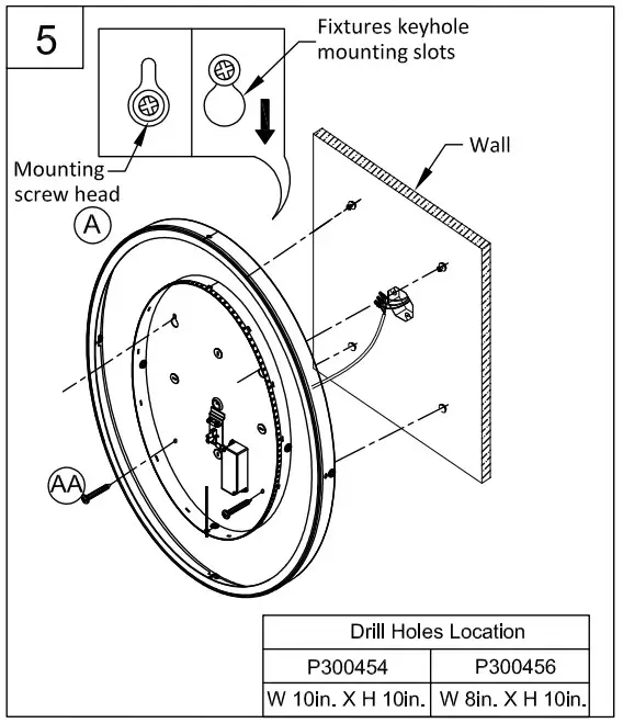
- Hang the mirror frame (A) by the top two keyhole slots in the back of the mirror frame (A). The mirror should be oriented so that the narrow portion of the keyhole faces up.
Next screw in the bottom two pan head self tapping screws (AA) through the bottom two circular slots in the back of the mirror frame (A). Make sure to tighten down the four pan head self tapping screws all together after they have been screwed in most of the way individually.
- Reinstall the mirror face (B) to mirror frame (A) and screw back down the four screws (C).
Note: Be careful to make sure the mirror face is securely attached to the mirror frame before letting go.
Note: P300454 outwire can be connected through the back or the bottom of metal frame.
P300456 outwire can be connected through the side or the bottom of metal frame.
FCC Statement
This equipment has been tested and found to comply with the limits for a Class B digital device, pursuant to part 15 of the FCC Rules. These limits are designed to provide reasonable protection against harmful interference in a residential installation. This equipment generates, uses and can radiate radio frequency energy and, if not installed and used in accordance with the instructions, may cause harmful interference to radio communications.However, there is no guarantee that interference will not occur in a particular installation.
If this equipment does cause harmful interference to radio or television reception, which can be determined by turning the equipment off and on, the user is encouraged to try to correct the interference by one or more of the following measures:
- Reorient or relocate the receiving antenna.
- Increase the separation between the equipment and receiver.
- Connect the equipment into an outlet on a circuit different from that to which the receiver is connected
- Consult the dealer or an experienced radio/TV technician for help.
Any changes or modifications to this unit not expressly approved by the party responsible for compliance could void the user’s authority to operate the equipment.
Support
THANK YOU forselecting Progress Lighting![]() We can assist you with questions regarding product information, assembly or missing parts
We can assist you with questions regarding product information, assembly or missing parts![]() 800-447-0573
800-447-0573
8am-8pm (Eastern), Monday-Friday![]() [email protected]
[email protected]