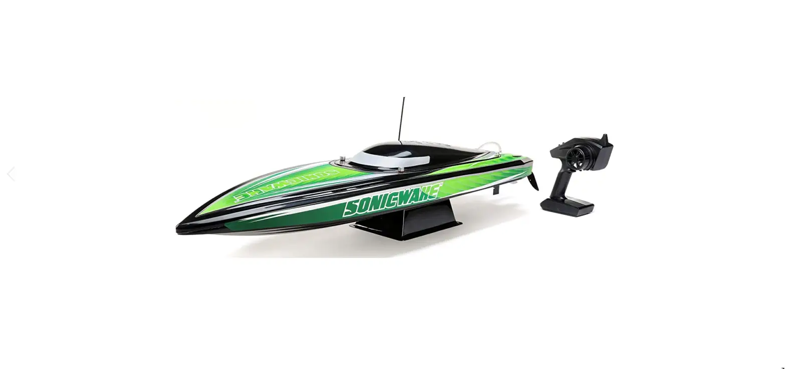
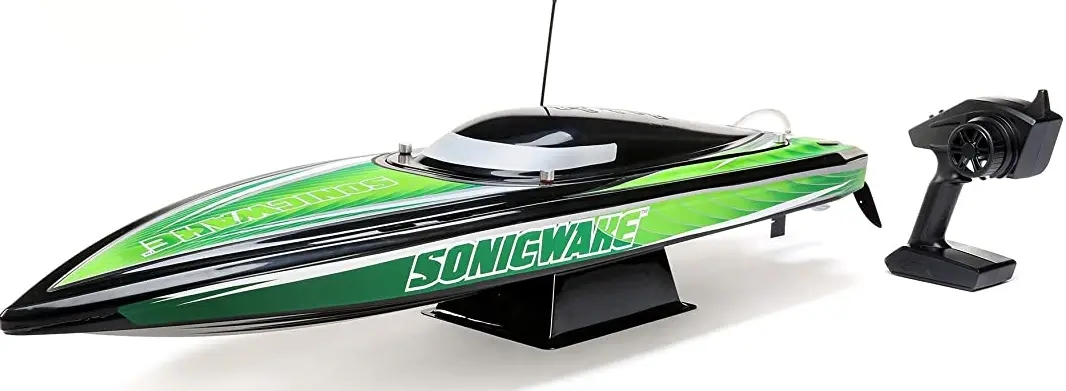
HORIZON PRB08032V2 Sonicwake 36 Inch Self Righting Deep-V Brushless RTR
Safety Precautions and Warnings
- As the user of this product, you are solely responsible for operating in a manner that does not endanger yourself and others or result in damage to the product or the property of others.
- When handling and/or transporting your boat, always pick up the boat from the front, keeping all moving parts pointed away from you.
- Always keep a safe distance in all directions around your model to avoid collisions or injury. This model is controlled by a radio signal subject to interference from many sources outside your control. Interference can cause momentary loss of control.
- Always operate your model in open spaces away from full-size vehicles, traffic and people.
- Always carefully follow the directions and warnings for this and any optional support equipment (chargers, rechargeable battery packs, etc.).
- Always keep all chemicals, small parts and anything electrical out of the reach of children.
- Always avoid water exposure to all equipment not specifically designed and protected for this purpose. Moisture causes damage to unprotected electronics.
- Never place any portion of the model in your mouth as it could cause serious injury or even death.
- Never operate your model with low transmitter batteries
Water-Resistant Boat with Waterproof Electronics
Your new Horizon Hobby boat has been designed and built with a combination of waterproof and water-resistant components to allow you to operate the product in calm, fresh water conditions. While the entire boat is highly water-resistant, it is not completely waterproof and your boat should NOT be treated like a submarine. The various electronic components used in the boat, such as the ESC, servo(s) and receiver are waterproof, however, most of the mechanical components are water-resistant and require additional maintenance after use. Metal parts, including the bearings, pins, screws and nuts, propeller, rudder, rudder mounts, prop struts, as well as the contacts in the electrical cables, will be susceptible to corrosion if additional maintenance is not performed after running in wet conditions. To maximize the long-term performance of your boat and to keep the warranty intact, the procedures described in the WET CONDITIONS MAINTENANCE section must be performed regularly
General Precautions
- Read the WET CONDITIONS MAINTENANCE procedures and make sure that you have all the tools you will need to properly maintain your boat.
- Not all batteries can be used in wet conditions. Consult the battery manufacturer before use. Caution should be taken when using Li-Po batteries in wet conditions.
- Most transmitters are not water-resistant. Consult your transmitter’s manual or the manufacturer before operation.
- Never operate your transmitter or boat when lightning is present.
- Saltwater is very conductive and highly corrosive. If you choose to run your boat in saltwater, immediately rinse the boat in fresh water after each use. Operating your boat in salt water is at the sole discretion of the modeler.
Box Contents
- Pro Boat® Sonicwake® V2 36-Inch Self-Righting Deep V RTR (PRB08032V2T1/T2
- Spektrum™ Firma Smart 120A Brushless Marine ESC 3–6S (SPMXME1120)
- Spektrum™ SR315 DSMR® 3-Channel Sport Receiver (SPMSR315)
- Spektrum™ 9KG Waterproof Servo (SPMS605)
- Spektrum™ SLT3™ 3-Channel Transmitter (SPMSLT350)
- Spektrum Firma 1900KV Marine Motor (SPMXMM3300)
Recommended Tools and Materials
- Needle nose pliers
- Paper towel
- Rubbing alcohol
- Open-end wrench: 10mm (2)
- Nut driver: 4mm, 5.5mm, 8mm
- Hex wrench: 1.5mm, 2mm, 2.5mm, 3mm
- Clear tape (DYNM0102)
- Pro Boat® Marine Grease and Gun
- Hook and Loop Tape Set, WP (4pcs)
- Clean towels
- CA or Epoxy Glue
- Ball driver: 2.5mm
Specifications
- Length 36 in. (914.4mm)
- Height 6.75 in. (171.45mm)
- Beam 11.0 in. (279.4mm)
- Hull Material Polycarbonate
- Recommended
- Battery (2) 11.1V 5000mAh 3S 100C
- Smart Hardcase LiPo Battery: IC5 (SPMX50003S100H5)
- (sold separately) are required to
- operate the boat.
Transmitter Functions
- Throttle Trim Adjusts the throttle neutral point
- Steering Trim Adjusts the steering center point. Normally, the steering trim is adjusted until the vehicle tracks straight.
- LED• Solid red lights: Indicates the power is ON and adequate battery power • Flashing red lights: Indicates the battery voltage is critically low. Replace batteries
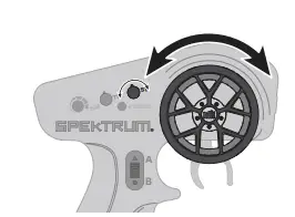
- Steering Wheel
- Throttle/Brake
- Steering Rate On-The-Fly knob for travel adjustment on the steering
- Channel 3 3 position momentary switch, middle position is neutral For programming press up for A button, press down for B button
- Throttle Limit Limits throttle output to 50/75/100% Select 50% or 75% for less experienced drivers or when you are driving the vehicle in a small area.
- Throttle (TH) Servo Reversing Move the switch to reverse the throttle channel
- Steering (ST) Servo Reversing Move the switch to reverse the steering channel
- Power Button
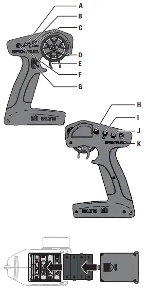
Installing the Transmitter Batteries
CAUTION: If using rechargeable batteries, charge only rechargeable batteries. Charging non-rechargeable batteries may cause the batteries to burst, resulting in injury to persons and/or damage to property. This transmitter requires 4 AA batteries.
- Remove the battery cover from the transmitter.
- Install the batteries as shown.
- Install the battery cover.
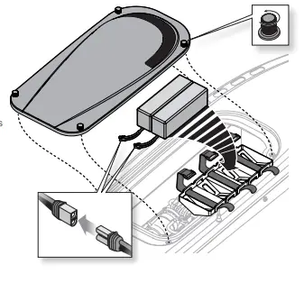
Battery Pack Installation
- Loosen the 4 canopy screws.
- Carefully lift the canopy from the hull.
- Install the batteries in the battery tray.
- Connect the battery packs to the ESC power connectors. Before placing your boat in the water, secure the canopy on the hull. Apply clear tape (DYNM0102), if desired.
TIP: Place the canopy flat onto the hull and secure the two front screws simultaneously. Then secure the two rear screws simultaneously. This helps prevent cross-threading and damage to the thumbscrews and/or threaded inserts. TIP: Begin with the batteries as far forward as possible, moving them back ½ inch (13mm) at a time toward the stern until the boat reaches maximum speed. Positioning the Battery Packs
- Toward the Bow: In rough water or strong wind conditions, place the battery packs at the front of the battery trays to ensure the greatest stability.
- Centered: Smooth water and calm winds may allow you to move the battery packs rear-ward in the hull to allow the bow to ride higher and increase speed. Be aware that positioning the batteries farther aft increases the likelihood of the boat blowing over at speed or becoming unstable.
- Toward the Stern: Positioning the batteries all the way back in their trays may provide higher top speeds but can cause instability. Experiment with this position only in very calm conditions while closely monitoring the hull’s attitude as you increase speed.
Low Voltage Cutoff (LVC)
The factory default setting for the LVC in the ESC included with your boat is set at 3.2V per cell. Discharging a Li-Po battery below 3V per cell may damage your battery. The included ESC protects the boat battery from over-discharge using Low Voltage Cutoff (LVC). Before the battery charge decreases too much, LVC removes the power supplied to the motor. The boat drastically slows or stops completely once LVC is activated. Releasing the throttle and reapplying it will provide a limited amount of power to safely return the boat to shore. Repeated use after LVC is activated will damage the batteries. Once LVC has been activated, the ESC status light will flash red continuously indicating that the ESC is in LVC mode.
NOTICE: Repeated operation to LVC will damage the battery. LVC can activate prematurely if you use (1) low C-rated batteries or (2) old, worn, and/or weak batteries.
Control Check
IMPORTANT: Perform a control check at the beginning of each boating session, after repair, or after installation of new batteries. Ensure the receiver antenna is extended properly and all batteries are fully charged.
- Power ON the transmitter and the boat. Do not install the boat canopy.
- Place the boat securely on the boat stand.
 \
\
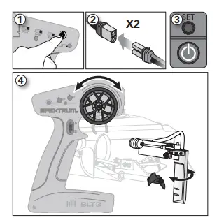
Getting Started
- Power on the transmitter.
- Connect the two batteries to the IC5® connectors on the ESC.
- Power on the ESC switch. The ESC arming tones will sound.
- Test the transmitter’s control of the boat with the boat on the display stand.
- Remove the rudder cover before operating the boat.
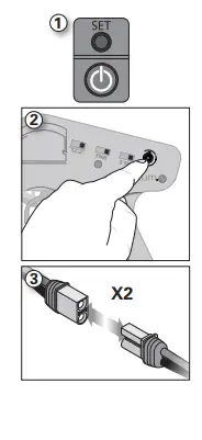
When You Are Finished
- Power off the ESC.
- Power off the transmitter.
- Disconnect and remove the battery from the boat. TIP: Always remove the canopy before storage or moisture may allow mold and mildew to grow in the boat.
- Drain water from inside the hull using the drain plug.
- Fully dry the inside and outside of the boat, including the water cooling lines and jacket around the motor. Carefully dry all battery, motor and receiver connectors by removing one at a time and reinstalling.
- Remove the hatch before storing your boat.
- Repair any damage or wear to the boat.
- Lubricate the flex shaft using Pro Boat® Marine Grease (DYNE4200 or DYNE4201).
- Note the lessons learned from the trimming of your boat, including water and wind conditions.
- Replace the rudder cover to protect the rudder’s sharp points
Boating Tips
During the first run, we recommend calm wind and water conditions to ensure that the boat is properly set up. Maximum speeds of 50 MPH/+ can be achieved once you have set up the boat for your specific conditions. Top speed will also be determined by the battery’s ability to efficiently deliver power to the motor via the ESC. Consult local laws and ordinances before choosing a location to pilot your boat.
- Carefully place the boat in the water.
- Operate the boat at slow speeds near the shoreline. Avoid objects in the water at all times. When the boat is moving forward, ensure water flows out of the coolant outlet.
- Once you are comfortable operating the boat at slow speeds, it is safe to operate the boat farther from the shore at higher speeds.
- Bring the boat back to shore when the motor starts to pulse.
Avoid boating near:
- watercraft
- people (swimming areas, fishing areas)
- stationary objects
- waves and wakes
- rapidly moving water
- wildlife
- floating debris
- overhanging trees
- vegetation
Self-Righting
The self-righting feature uses a water ballast system. The ballast works as a controlled breach in the hull. As the ballast fills with water, the weight of the water forces the boat to sink, while the air trapped inside the hull causes enough buoyancy to right the boat. The boat will self-right automatically, using water ballast. Once the boat is upright, it will lean to one side. Apply full throttle. The trapped water will be forced out of the ballast tanks by the boat’s forward momentum.
IMPORTANT: Applying throttle during the self-righting process may prevent the boat from turning over.
Maintenance
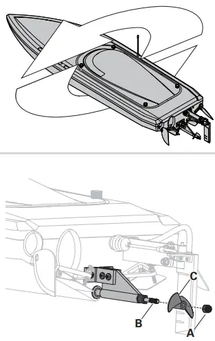
Propeller Service
- Use an 8mm nut driver to loosen the nut (A) from the driveshaft (B).
- Remove the nut and propeller (C) from the driveshaft.
- Inspect the propeller for any damage or wear and replace as necessary.
- Assemble in reverse order. Correctly align the propeller with the drive dog on the driveshaft.
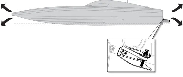
Trim Tab Adjustment
The trim tabs come installed from the factory to stabilize the boat as it rides across the water. They are set for consistent performance and stability in most water conditions. However, you can tune out chime walk or porpoise effect by adjusting the trim tabs so they are at least 1–1.5 mm below the ride surface of the boat. Adjusting the tabs up or down allows the boat to come in more or less contact with the water, resulting in either a smooth, planted ride or a fast, loose ride.
- Position a ruler parallel to the keel on the right side of the right trim tab, allowing the ruler to extend past the trim tab.
- To adjust the angle of the trim tab, loosen the locking nut on the adjustment screw, and then tighten the screw.
- Use a ruler to measure and record the tab adjustment. Measure the length of the bolt head to the base of the aluminum trim tab arm.
- Record the position of the trim tab against the ruler’s straight edge after adjusting the trim tab.
- Tighten the adjustment lock nut to prevent further movement of the adjustment screw.
- Repeat this process on the left trim tab, ensuring the trim tab panels are either perpendicular to or parallel to the bottom of the boat.
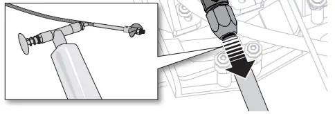
Drivetrain Lubrication
Always replace the drivetrain parts when they are damaged or show visible wear or injury and damage may result. Lubricating the drive shaft is vital to the life of the drivetrain. The lubricant also acts as a water seal, keeping water from entering the hull through the stuffing tube. Lubricate the drive shaft and all moving parts after every 20 minutes of operation.
- In the hull, use two 10 mm open-end wrenches to loosen the motor coupler. Slide the driveshaft out from the stuffing tube and drive
- strut at the rear of the boat.
- Wipe the old lubricant and material from the drive shaft.
- Apply a liberal amount of lubrication to the flex shaft and spread it around the entire shaft. Ensure enough lubrication is on the shaft to prevent any dry areas. NOTICE: When lubricating the flex shaft, do not lubricate the first 20mm of the flex shaft. If grease gets into the motor coupler, it may cause the flex shaft to slip inside of the coupler, thereby damaging it and requiring replacement.
- Carefully reinstall the drive shaft. Rotate it to spread the grease on the inside of the stuffing tube, ensuring that there is a 1–2mm gap between the propeller strut and the drive dog. This will allow space for the shaft as it shrinks under load. Without space, the drive dog could damage the aluminum propeller strut
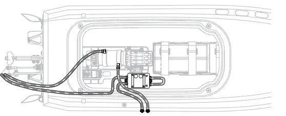
Water Cooling System
If water does not stream out of the right-side water outlet while the boat is moving forward, immediately stop the boat and clean the obstruction from the water-cooling system.
- Disassemble and clean the water cooling system to remove blockage and prevent overheating.
- Replace any damaged parts.
General Information
Receiver Antenna
The SR315 receiver features a coaxial antenna design for easy installation in almost any model. The last 1 inch (32mm) on the tip of the antenna is the active portion of the antenna. Install the antenna so the active portion is positioned as high as pos-sible in the vehicle and not “in the shadow” of any carbon fiber or metal. The receiver case can accept an antenna tube directly, making optimal antenna placement easy (antenna tube not included).
SLT Binding
Binding is the process of programming the receiver to recognize the GUID (Globally Unique Identifier) code of a single specific transmitter.
- Power ON the receiver, press the bind button three times quickly (within 1.5 seconds of the first button press). The LED will begin to flash with a pause.
- Set the trims and control positions at the desired failsafe settings, and power ON the SLT3 transmitter.
- When the LED on the SLT3 transmitter and receiver remain lit, binding is complete.
Servo Travel
The servo travel on the Steering and Throttle channels can be adjusted through a special programming mode in the transmitter.
- Begin with the transmitter binding process to the receiver complete. Power ON the receiver.
- Hold full right and full brake while powering the transmitter ON to put the transmitter into programming mode. The LED on the transmitter will flash 4 times to indicate it is in programming mode.
- Turn and hold the wheel full left to set the travel limit for that direction, Press the A button to increase travel, press the B button to reduce travel. The LED will flash once with every change. Return the wheel to center to set the travel value.
- 4. Turn the wheel to the right and repeat the process to set the steering travel to the right.
- For electric vehicles, power the Transmitter OFF to save the settings. Calibrate your ESC to the default throttle travel.
- For fuel powered vehicles, set the throttle travel without the engine running; After setting steering travel, you can set throttle travel with the same process. Pull and hold full throttle, adjust travel with the A and B buttons, return to center to set the value.
- Push full brake, adjust travel with the A and B buttons, return to center
- Power the transmitter OFF to save the values.
To Bind in Standard Mode:
- Center the throttle trim knob on the transmitter and ensure the throttle trigger is at the neutral position.
- Push and hold the receiver bind button.
- Power on the reciever. The receiver LED will flash rapidly.
- Release the receiver bind button.
- Push and hold the transmitter bind button.
- Power on the transmitter. The transmitter power LED will flash and glow solid when binding is complete.
- Release the transmitter bind button.
Failsafe
In the unlikely event that the radio connection is lost during use, the receiver will drive the servo and ESC to their pre-programmed failsafe positions (normally no throttle and straight steering).
ESC and Transmitter Calibration
- Begin with the transmitter and receiver binding complete.
- Set your transmitter’s throttle channel to 100% travel and trim to neutral.
- Turn on your transmitter and connect a battery to the ESC but don’t power it on.
- Press and hold the Set button while turning on the ESC. When the red LED begins to flash, release the Set button. The ESC will enter programming mode if the button is pressed for more than three seconds.
- Leave the throttle trigger at the neutral position, then press and release the Set button. The red LED will stop fl ashing, the green LED will fl ash one time and the motor will make a tone to indicate the neutral position has been accepted.
- Hold the throttle trigger at the full throttle position then press and release the Set button. The green LED will fl ashe twice and the motor will make two tones to indicate the full throttle position has been accepted.
- Hold the throttle trigger at the full brake position then press and release the Set button. The green LED will fl ash three times and the motor will make three tones to indicate the full brake position has been accepted.
Programming with the Smart Programmer Box
- Unplug the fan and connect the programming lead to the fan port.
- Connect a battery to the ESC.
- Power on the box and select the parameter with the SELECT button.
- Change the values of the selected parameter with the EDIT button.
- Press the SAVE button to save the changes. The ESC requires a power cycle to implement the saved changes.
Operation
1. Connect a battery to the ESC.
2. Leave the transmitter throttle at neutral and press the On/Off button on the ESC to turn it on. The ESC will cause the motor to make several tones.The number of tones indicates (1) the ESC is in operation (2) the LiPo cell count detected and (3) the ESC is in a ready-to-use state.
| LED Indicator | LED Code |
| ESC turned On, LED indicator is Off | Throttle trigger is in the neutral zone |
| Red LED illuminated | ESC is operating in forward, reverse or brake |
| Red and Green LED illuminated | ESC is at full throttle, full brake, or full reverese |
| LED flashes red with short single pulses | LVC protection activated |
| LED flashes green with short single pulses | The ESC is in thermal shutoff mode |
| LED flashes green with three short pulses repeating | The ESC has exceeded the continuous current limit |
| LED flashes green with four short pulses repeating | The ESC has failed the self test |
| LED flashes green with five short pulses repeating | Capacitor temperature has been exceeded |
Troubleshooting Guide
| Problem | Possible Cause | Solution |
| Boat will not respond to throttle but responds to other controls | Throttle channel is reversed | Reverse throttle channel on transmitter |
| Extra noise or extra vibration | Damaged propeller, shaft or motor | Replace damaged parts |
| Propeller is out of balance | Balance or replace propeller | |
| Boat squeals or makes a high pitch sound when applying power to motors | Lubricate flex shafts | |
|
Reduced runtime or boat underpowered | Boat battery charge is low | Completely recharge battery |
| Boat battery is damaged | Replace boat battery and follow battery instructions | |
| Blocking or friction on shaft or propeller | Disassemble, lubricate and correctly align parts | |
| Boat conditions may be too cold | Make sure the battery is warm (above 10º C [50º F]) before use | |
| Battery capacity may be too low for conditions | Replace battery or use a larger capacity battery | |
| Drive dog is too near the stuffing tube | Loosen drive shaft side of the motor coupling and move drive shaft small amount back | |
| Too little lubrication on drive shaft | Fully lubricate drive shaft | |
| Vegetation or other obstacles block the rudder or propeller | Remove vegetation or obstacles from rudder or propeller | |
| Motor couplers are loose | Tighten motor couplers and ensure the coupler is free of lubrication | |
|
Boat will not bind (during binding) to transmitter | Transmitter is too near boat during binding process | Move powered transmitter a few feet from boat, disconnect and reconnect battery to boat |
| Boat or transmitter is too close to large metal object, wireless source or another transmitter | Move the boat and transmitter to another location and attempt binding again | |
| Another compatible transmitter is powered on within range of the receiver | Power off all compatible transmitters except the one you are trying to bind | |
| Incorrect binding protocol set | Verify binding procedure and use SLT binding for stock radio. If using a DSMR or DSM2 utilize the standard binding procedure listed in the manual | |
| Boat battery/Transmitter battery charge is too low | Replace/recharge batteries | |
| ESC switch is off | Power on ESC switch | |
|
Boat will not connect (after binding) to transmitter | Transmitter is too near boat during connecting process | Move powered transmitter a few feet from boat, disconnect and reconnect battery to boat |
| Boat or transmitter is too close to large metal object, wireless source or another transmitter | Move boat or transmitter to another location and attempt to connect again | |
| Boat battery/transmitter battery charge is too low | Replace/recharge batteries | |
| ESC switch is off | Power on ESC switch | |
| Boat tends to dive in the water or takes on water | Boat hull is not completely closed | Dry out the boat and ensure the hatch is fully closed on the hull before returning the boat to the water |
| Trim tabs are adjusted too deep | Adjust trim tabs up | |
| Center of gravity is too far forward | Move batteries back in the hull | |
| Boat tends to turn one direction | Rudder or rudder trim is not centered | Repair rudder or adjust rudder and rudder trim for straight running when control is at neutral |
| Break away screw is damaged or broken | Replace damaged screw | |
| ESC may require full throttle range calibration | Calibrate the ESC | |
|
Rudder does not move | Rudder, linkage or servo damage | Replace or repair damaged parts and adjust controls |
| Steering servo wire is damaged or connections are loose | Do a check of steering servo wires and connections, connect or replace as needed | |
| Transmitter is not bound correctly | Re-bind | |
| BEC of the ESC is damaged | Replace ESC | |
| ESC switch is off | Power on ESC switch | |
| Controls reversed | Transmitter settings are reversed | Do the Control Direction Test and adjust controls on transmitter appropriately |
| Motor overheats | Blocked water cooler tubes | Clean or replace water tubes |
| Problem | Possible Cause | Solution |
| Motor power pulses then motor loses power | ESC uses default soft Low Voltage Cutoff (LVC) | Recharge boat battery or replace battery that is no longer performing |
| Weather conditions might be too cold | Postpone until weather is warmer | |
| Battery is old, worn out or damaged | Replace battery | |
|
Boat blows over upon acceleration | Batteries are too far back in the battery tray | Move the batteries forward to adjust the boat’s center of gravity |
| Struts have too much positive angle, causing the nose of the boat to lift and blow over | Adjust a more neutral or negative strut angle | |
| Trim Tabs not adjusted, causing the nose of the boat to lift and blow over | Adjust the trim tabs further into the water to keep the nose of the boat in the water and provide additional stability | |
| Water conditions are too choppy or windy | Adjust the struts downward to drive the bow of the boat down or move the batteries further forward for better weight distribution |
Warranty
- What This Warranty Covers — Horizon Hobby, LLC, (Horizon) warrants to the original purchaser that the product purchased (the “Product”) will be free from defects in materials and work- manship for two years from the date of purchase.
- What is Not Covered — This warranty is not transferable and does not cover (i) cosmetic damage, (ii) damage due to acts of God, accident, misuse, abuse, negligence, commercial use, or due to improper use, installation, operation or maintenance, (iii) modification of or to any part of the Product, (iv) attempted ser- vice by anyone other than a Horizon Hobby authorized service center, (v) Product not purchased from an authorized Horizon dealer, or (vi) Product not compliant with applicable technical regulations or (vii) use that violates any applicable laws, rules, or regulations. OTHER THAN THE EXPRESS WARRANTY ABOVE, HORIZON MAKES NO OTHER WARRANTY OR REPRESENTATION, AND HEREBY DISCLAIMS ANY AND ALL IMPLIED WARRANTIES, INCLUDING, WITHOUT LIMITATION, THE IMPLIED WARRANTIES OF NON-INFRINGEMENT, MERCHANTABILITY AND FITNESS FOR A PARTICULAR PURPOSE. THE PURCHASER ACKNOWLEDGES THAT THEY ALONE HAVE DETERMINED THAT THE PRODUCT WILL SUITABLY MEET THE REQUIREMENTS OF THE PURCHASER’S INTENDED USE.
- Purchaser’s Remedy — Horizon’s sole obligation and pur- chaser’s sole and exclusive remedy shall be that Horizon will, at its option, either (i) service, or (ii) replace, any Product deter- mined by Horizon to be defective. Horizon reserves the right to inspect any and all Product(s) involved in a warranty claim. Service or replacement decisions are at the sole discretion of Horizon. Proof of purchase is required for all warranty claims. SERVICE OR REPLACEMENT AS PROVIDED UNDER THIS WARRANTY IS THE PURCHASER’S SOLE AND EXCLUSIVE REMEDY.
- Limitation of Liability — HORIZON SHALL NOT BE LIABLE FOR SPECIAL, INDIRECT, INCIDENTAL OR CONSEQUENTIAL DAMAGES, LOSS OF PROFITS OR PRODUCTION OR COM- MERCIAL LOSS IN ANY WAY, REGARDLESS OF WHETHER SUCH CLAIM IS BASED IN CONTRACT, WARRANTY, TORT, NEGLIGENCE, STRICT LIABILITY OR ANY OTHER THEORY OF LIABILITY, EVEN IF HORIZON HAS BEEN ADVISED OFTHE POSSIBILITY OF SUCH DAMAGES. Further, in no event shall the liability of Horizon exceed the individual price of the Product on which liability is asserted. As Horizon has no control over use, setup, final assembly, modification or misuse, no liability shall be assumed nor accepted for any resulting damage or injury. By the act of use, setup or assembly, the user accepts all resulting liability. If you as the purchaser or user are not prepared to accept the liability associated with the use of the products, purchaser is advised to return the Product immediately in new and unused condition to the place of purchase.
- Law — These terms are governed by Illinois law (without regard to conflict of law principals). This warranty gives you specific legal rights, and you may also have other rights which vary from state to state. Horizon reserves the right to change or modify this warranty at any time without notice.
- Questions, Assistance, and Services — Your local hobby store and/or place of purchase cannot provide warranty support or service. Once assembly, setup or use of the Product has been started, you must contact your local distributor or Horizon directly. This will enable Horizon to better answer your questions and service you in the event that you may need any assis- tance. For questions or assistance, please visit our website at www.horizonhobby.com, submit a Product Support Inquiry, or call the toll free telephone number referenced in the Warranty and Service Contact Information section to speak with a Product Support representative.
- Inspection or Services — If this Product needs to be inspected- ed or serviced and is compliant in the country you live and use the Product in, please use the Horizon Online Service Request submission process found on our website or call Horizon to obtain a Return Merchandise Authorization (RMA) number.Pack the Product securely using a shipping carton. Please note that original boxes may be included, but are not designed to withstand the rigors of shipping without additional protection. Ship via a carrier that provides tracking and insurance for lost or damaged parcels, as Horizon is not responsible for merchandise until it arrives and is accepted at our facility. An Online Service Request is available at http://www.horizonhobby. com/content/service-center_render-service-center. If you do not have internet access, please contact Horizon Product Support to obtain an RMA number along with instructions for submitting your product for service. When calling Horizon, you will be asked to provide your complete name, street address, email address and phone number where you can be reached during business hours. When sending products into Horizon, please include your RMA number, a list of the included items, and a brief summary of the problem. A copy of your original sales receipt must be included for warranty consideration. Be sure your name, address, and RMA number are clearly written on the outside of the shipping carton.
- Warranty Requirements — For Warranty consideration, you must include your original sales receipt verifying the proof-of-purchase date. Provided warranty conditions have been met, your Product will be serviced or replaced free of charge. Service or replacement decisions are at the sole discretion of Horizon.
| Country of Purchase | Horizon Hobby | Contact Information | Address |
|
United States of America | Horizon Service Center (Repairs and Repair Requests) | servicecenter.horizonhobby.com/RequestForm/ |
2904 Research Rd. Champaign, Illinois, 61822 USA |
| Horizon Product Support (Product Technical Assistance) | [email protected] | ||
| 877-504-0233 | |||
| Sales | [email protected] | ||
| 800-338-4639 | |||
| EU | Horizon Technischer Service | [email protected] | Hanskampring 9 D 22885 Barsbüttel, Germany |
| Sales: Horizon Hobby GmbH | +49 (0) 4121 2655 100 |
FCC Information
This equipment complies with FCC and IC radiation exposure limits set forth for an uncontrolled environment. This equipment should be installed and operated with a minimum distance 20cm between the radiator and/or antenna and your body (excluding fingers, hands, wrists, ankles and feet). This transmitter must not be co-located or operating in conjunction with any other antenna or transmitter. This equipment generates, uses and can radiate radio frequency energy and, if not installed and used in accordance with the instructions, may cause harmful interference to radio communications. However, there is no guarantee that interference will not occur in a particular installation. If this equipment does cause harmful interference to radio or television reception, which can be determined by turning the equipment off and on, the user is encouraged to try to correct theinterference by one or more of the following measures:
- Reorient or relocate the receiving
- Increase the separation between the equipment and receiver.
- Connect the equipment into an outlet on a circuit different from that to which the receiver is connected.
- Consult the dealer or an experienced radio/TV technician for help.
Horizon Hobby, LLC 2904 Research Rd., Champaign, IL 61822 Email: [email protected] Web: HorizonHobby.com
Replacement Parts
| Part # | English | Deutsch | Français | Italiano |
| PRB281074 | Canopy, Black | Verdeck, Schwarz | Verrière, Noire | Capottina, Nera |
| PRB281068 | Canopy, White | Verdeck, Weiß | Verrière, Blanche | Capottina, Bianca |
| PRB281118 | Pro Boat Water Resistant Receiver Box | Pro Boat Wasserdichte Empfänger-Box | Récepteur Pro Boat résistant à l’eau | Scatola ricevitore resistente all’acqua Pro Boat |
| PRB281124 | Trim Tab Set | Trimmklappen-Satz | Ensemble volet compensateur | Set correttori assetto |
| PRB281125 | Turn Fin Set | Drehflossensatz | Ensemble dérive de rotation | Set pinne di virata |
| PRB281126 | Rudder Set | Rudersatz | Ensemble gouvernail | Set timone |
| PRB281127 | Hull, Black | Schiffskörper, Schwarz | Coque, Noire | Scafo, Nero |
| PRB281128 | Hull, White | Schiffskörper, Weiß | Coque, Blanche | Scafo, Bianca |
| PRB282055 | Propeller, 1.73 x 1.6: 3/16 Shaft | Propeller, 1,73 x 1,6: 3/16 Welle | Hélice, 1,73 x 1,6 : Arbre 3/16 | Elica 1,73 x 1,6: Albero 3/16 |
| PRB282056 | Flex Shaft | Flexwelle | Arbre flexible | Albero flessibile |
| PRB282093 | Propeller Strut | Propellerstange | Hauban de l’hélice | Supporto elica |
| PRB282094 | Stuffing Tube | Füllrohr | Tube de remplissage | Tubo ingrassatore |
| PRB285002 | Break Away Bolt | Abreißschraube | Boulon à rupture | Bullone frangibile |
| PRB286056 | Motor Coupler: 5mm (Motor) 4.7mm (Flexshaft) | Motorkupplung: 5 mm (Motor) 4,7 mm (Flexwelle) | Coupleur du moteur : 5 mm (moteur) 4,7 mm (arbre flexible) | Accoppiamento motore: 5 mm (motore) 4,7mm (albero flessibile) |
| PRB286058 | Miscellaneous Hardware | Diverse Hardware | Matériel divers | Hardware vario |
| PRB286084 | Canopy Thumb Screw Set | Daumenschraubensatz für Kabinendach | Ensemble vis à oreilles de la verrière | Kit viti zigrinate capottina |
| PRB286095 | Rudder Cover | Ruderabdeckung | Protection du gouvernail | Coperchio timone |
| PRB286096 | Servo Mount Set | Servohalterungssatz | Ensemble support de servo | Set supporto servo |
| PRB286097 | Motor Mount Set | Motorhalterung | Support moteur | Montante motore |
| PRB289008 | Decal Set T1/T2 Sonicwake 36 V2 | Decal-Satz T1/T2 Sonicwake 36 V2 | Feuillet d’autocollants T1/T2 Sonicwake 36 V2 | Set adesivi T1/T2 Sonicwake 36 V2 |
| SPMS605 | 9KG Servo, WP, Metal, 23T | Spektrum S605 9KG WP-Metall-Servo 23T | Servo 9Kg à pignons métal, étanche, tête 23T | Servocomando 9kg, WP, ingranaggio in metallo, 23T |
| SPMSR315 | SR315 DSMR 3CH Receiver | SR315 DSMR 3CH Empfänger | Récepteur 3 canaux SR315 DSMR | Ricevitore SR315 DSMR 3 canali |
| SPMSLT300 | SLT3 3-Channel SLT Radio System with SR315 Dual Protocol | SLT3 3-Kanal-SLT- Funksystem mit SR316 Dual-Protokoll | Système radio SLT à 3 canaux SLT3 avec double protocole SR316 | Radiocomando SLT-3 a 3 canali con SR316 a doppio protocollo |
| SPMXME1120 | Firma 120A BL Smart Marine ESC 3-6S | Firma 120A BL Smart-Marine- Geschwindigkeitsregler 3–6S | Variateur ESC marin 120 A sans balais Smart Firma 3–6S | ESC Firma 120A BL Smart Marine 3-6S |
| SPMXMM3300 | Firma 1900KV Brushless Marine Motor | Firma 1900KV bürstenloser Schiffsmotor | Moteur marin sans balais Firma 1900 KV | Motore marino Firma 1900 Kv Brushless |
Optional Parts
| Part # | English | Deutsch | Français | Italiano |
| DYN2803 | Nut Driver: 5.5mm | Dynamite Steckschlüssel:5.5mm | Clé à écrou 5,5mm | Chiave per dadi: 5,5mm |
| DYN2805 | Nut Driver: 8mm | Dynamite Steckschlüssel:8mm | Clé à écrou 8mm | Chiave per dadi: 8mm |
| DYN2819 | 5 pc Metric Hex Driver Assortment | Dynamite metrischer Inbusschlüsselsatz 1,5-4 mm (5 Stk) | Assortiment de 5 clé hexagonales métriques | Set chiavi esagonali metrici (5 pz) |
| DYN4403 | Passport GPS Speed Meter 2.0 | GPS Tachometer 2.0 | Indicateur de vitesse GPS 2.0 Passport | Tachimetro Passport GPS 2.0 |
| DYN5500 | Magnum Force 2 Motor Spray, 13oz | Magnum Force 2 Motorspray, 368 g | Vaporisateur pour moteur Magnum Force 2, 369 g (13 oz) | Spray motore Magnum Force 2, 385 ml |
| DYNE4200 | Grease Gun with Marine Grease 5 oz | Dynamite Fettpresse m. Marinefett 141 g | Pistolet avec graisse marine 140g | Grasso marino con pistola 5 oz |
| DYNE4201 | Marine Grease 5 oz | Dynamite Marinefett 141 g | Graisse marine 140g | Grasso marino 5 oz |
| DYNF1055 | Infrared Temp Gun with Laser | Infrarotmesspistole mit Laser | Détecteur infrarouge de température avec laser | Pistola misuratrice temperatura a infrarossi con puntamento laser |
| DYNK0300 | Hook and Loop Tape Set, Waterproof 75 x 25mm 4pcs | Dynamite Klettbandset 75 x 25mm (4 Stk) | Adhésif auto-agrippant 75 x 25mm (4pcs) | Set nastro a strappo, WP 75 x 25mm 4pz |
| DYNM0102 | Clear Flexible Marine Tape (18M) | Dynamite transparentes Marineklebeband 18 m | Adhésif Marin transparent flexible (18M) | Nastro marino trasparente flessibile (18M) |
| DYNT0502 | Start Up Tool Set: Pro Boat | Dynamite Startup Werkzeugset: Pro Boat | Pro Boat – Set d’outils de démarrage | Start Up Tool Set: Pro Boat |
| PRB282028 | Propeller, CCW, 1.4 x 1.65: 3/16 Shaft | Propeller, CCW 1,4 x 1,65: 3/16 Welle | Hélice, CCW, 1,4 x 1,65 : Arbre 3/16 | Elica, rotazione antioraria, 1,4 x 1,65: Albero 3/16 |
| PRB282047 | Propeller, 1.7 x 1.6: 3/16 Shaft | Propeller, 1,7 x 1,6: 3/16 Welle | Hélice, 1,7 x 1,6 : Arbre 3/16 | Elica 1,7 x 1,6: Albero 3/16 |
| SPMMR4000 | MR4000 DSMR 4CH Marine Receiver | MR4000 DSMR 4 Kanal Bootsempfänger | Récepteur marin MR4000 DSMR 4 canaux | Ricevitore marino MR4000 4 canali DSMR |
| SPMSS6170 | S6170 M-T / M-S Digital WP Servo | S6170 M-T / M-S Digitaler WP Servo | Servo impermeabile digitale M-S / S6170 M-T | Servo numérique étanche S6170 M-T/M-S |
| SPMSS6250 | S6250 U-T / H-S Digital HV WP Servo | S6250 U-T / H-S Digitaler HV WP Servo | Servo numérique étanche S6250 U-T / H-S HV | Servo impermeabile digitale HV H-S / S6250 U |
| SPMX53S100H5 | 11.1V 5000mAh 3S 100C Smart G2 Hardcase LiPo Battery: IC5 | 11,1 V 5000 mAh 3S 100C Smart G2 LiPo-Akku, Hartschale: IC5 | Batterie Li-Po Smart 11,1 V 5000 mAh 3S 100C G2, boîtier rigide : IC5 | Batteria 11,1 V 5000 mAh 3S 100C Smart G2 Hardcase LiPo: IC5 |
| SPMX50003S50H5 | 11.1V 5000mAh 3S 50C Smart Hardcase LiPo Battery: IC5 | 11,1 V 5000 mAh 3S 50C Smart LiPo-Akku, Hartschale: IC5 | Batterie Li-Po Smart 11,1 V 5000 mAh 3S 50C, boîtier rigide : IC5 | Batteria 11,1 V 5000 mAh 3S 50C Smart Hardcase LiPo: IC5 |
| DYN4403 | Passport GPS Speed Meter 2.0 | Passport GPS Tachometer 2.0 | Indicateur de vitesse GPS 2.0 Passport | Tachimetro Passport GPS 2.0 |
| SPMXPS6 | Smart PowerStage Bundle 6S | Smart PowerStage- Paket 6S | Ensemble Smart Powerstage 6S | Smart Powerstage Bundle 6S |
| SPMXCA200 | Avian Firma Smart ESC Programmer | Avian Firma Smart ESC Programmer | Programmateur ESC Smart Firma Avian | Programmer Smart ESC Avian Firma |
| SPMXSE1160M | Firma 160A Smart BL Marine ESC | Firma 160A Smart BL Marine ESC | Variateur ESC marin sans balais Firma 160 A Smart | ESC marino Firma 160A Smart BL |
References
 RC Airplanes and Helicopters, RC Cars and Trucks, RC Boats, RC Radios | Horizon Hobby
 Product Service Center - Request Form
-
RC Airplanes and Helicopters, RC Cars and Trucks, RC Boats, RC Radios | Horizon Hobby
-
Horizon Hobby Service Center
-
RC Cars, RC Trucks, RC Airplanes, Model Trains, and Slot Cars at Tower Hobbies
-
RC Airplanes and Helicopters, RC Cars and Trucks, RC Boats, RC Radios | Horizon Hobby


