![]()
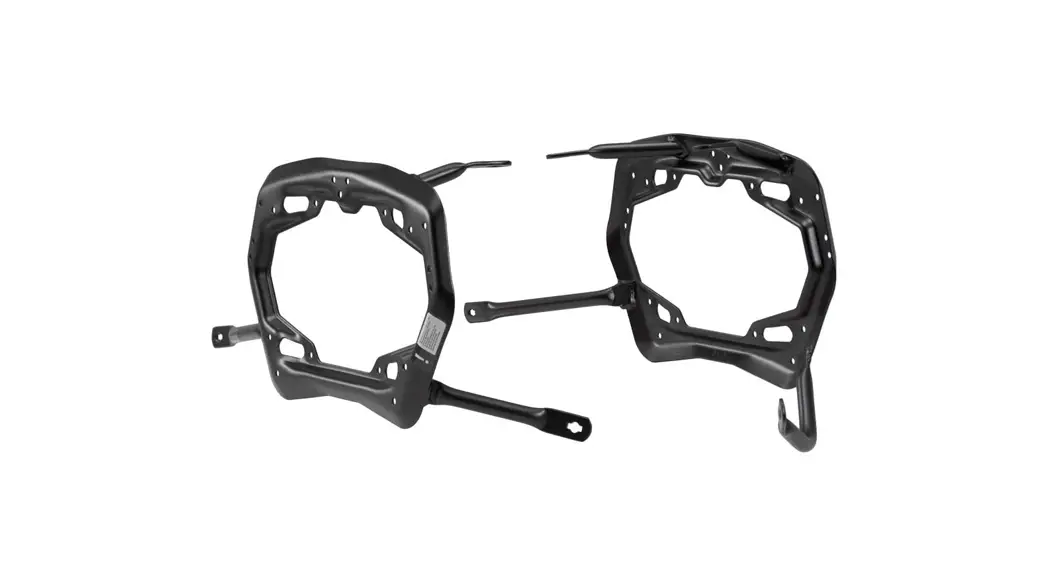
kft 08 922 30001 b Pro Side Carrier
Instruction Manual
kft 08 922 30001 b Pro Side Carrier
MOUNTING INSTRUCTIONS • READ AND SAVE THESE MOUNTING INSTRUCTIONS
Thank you for choosing this premium product from SW-MOTECH. Please carefully read and understand all instructions, safety messages and warnings in this mounting instructions prior to installation and use of this product to avoid injury.
This product was developed for vehicles in their factory setting. Compatibility with original accessory parts or other manufacturers’ accessory parts is not guaranteed. Visit our webshop for additional information, such as application charts and PDF mounting instructions. Any other documents that may be required (e.g. ABE certifications), are also available for download at our webshop. Keep these mounting instructions as reference.
SW-MOTECH assumes no liability for damage caused by improper installation and/or maintenance work!
SAFETY ALERT SYMBOL
This safety alert symbol is used throughout these mounting instructions to warn of the possibility of death, bodily injury or other warnings. The words DANGER, WARNING and CAUTION are used with this safety alert symbol to convey important safety messages and information related to the installation and use of this product. These words along with the safety alert symbol mean:![]() DANGER: Indicates a hazardous situation that, if not avoided, will result in death or serious injury!
DANGER: Indicates a hazardous situation that, if not avoided, will result in death or serious injury!![]() WARNING: Indicates a hazardous situation that, if not avoided, could result in death or serious injury!
WARNING: Indicates a hazardous situation that, if not avoided, could result in death or serious injury!![]() CAUTION: Indicates a hazardous situation that, if not avoided, could result in minor or moderate injury!
CAUTION: Indicates a hazardous situation that, if not avoided, could result in minor or moderate injury!![]() NOTICE: Important information, but not death or injury related (property damage only)!
NOTICE: Important information, but not death or injury related (property damage only)!
![]() WARNING: The installation and/or maintenance of this product requires advanced mechanical skills, the proper tools, and a thorough understanding of tool use and torque specifications. For your own safety, SW-MOTECH recommends having installation and/or maintenance carried out by a qualified and certified motorcycle mechanic.
WARNING: The installation and/or maintenance of this product requires advanced mechanical skills, the proper tools, and a thorough understanding of tool use and torque specifications. For your own safety, SW-MOTECH recommends having installation and/or maintenance carried out by a qualified and certified motorcycle mechanic.![]() WARNING: Should you choose to self-install this product, carefully and completely read all intallation and safety instructions before installation and use, and follow all the directions and safety precautions given in the mounting instructions to avoid serious injury or death. Also pay attention to all relevant information in the vehicle manual during intallation and use.
WARNING: Should you choose to self-install this product, carefully and completely read all intallation and safety instructions before installation and use, and follow all the directions and safety precautions given in the mounting instructions to avoid serious injury or death. Also pay attention to all relevant information in the vehicle manual during intallation and use.![]() YOU DO NOT UNDERSTAND ANY PART OF THESE INSTRUCTIONS, OR NEED CLARIFICATION OF ANY INSTRUCTION, DO NOT ATTEMT TO MOUNT THIS PRODUCT WITHOUT CONTACTING SW-MOTECH FOR ASSISTANCE.
YOU DO NOT UNDERSTAND ANY PART OF THESE INSTRUCTIONS, OR NEED CLARIFICATION OF ANY INSTRUCTION, DO NOT ATTEMT TO MOUNT THIS PRODUCT WITHOUT CONTACTING SW-MOTECH FOR ASSISTANCE.
PREPARATION: Read the mounting instructions carefully and make sure that all items of the parts list are included.![]() CAUTION: Make sure that your vehicle is parked safely and cannot fall over. Turn off the engine and remove the ignition key. Let the engine/exhaust cool off if necessary. Disconnect the vehicle battery when working on the electrical system. Use appropriate tools and wear always safety glasses and hand protection. Have another person help you.
CAUTION: Make sure that your vehicle is parked safely and cannot fall over. Turn off the engine and remove the ignition key. Let the engine/exhaust cool off if necessary. Disconnect the vehicle battery when working on the electrical system. Use appropriate tools and wear always safety glasses and hand protection. Have another person help you.
MOUNTING: All parts and connections removed from the vehicle must be reinstalled in accordance with the vehicle manufacturer specifications or replaced by parts and hardware delivered by SW- MOTECH.![]() WARNING: Secure all threads, unless otherwise specified, with medium-strong strength liquid thread locker. Torque specifications undefined by SW-MOTECH must be obtained from the vehicle manufacturer or by a certified motorcycle workshop!
WARNING: Secure all threads, unless otherwise specified, with medium-strong strength liquid thread locker. Torque specifications undefined by SW-MOTECH must be obtained from the vehicle manufacturer or by a certified motorcycle workshop!
FUNCTION CHECK: After installation also make sure that no moving parts are obstructed, and function of the vehicle is not hindered in any way. Cables and hoses must not rub and/or be pinched.![]() WARNING: Before starting to ride, perform a comprehensive check of all functions. After the first 50 km and then at regular intervals, check the tightening torque of all connections and the proper fit of the product. Installed accessories can change driving behavior/stability of the vehicle.
WARNING: Before starting to ride, perform a comprehensive check of all functions. After the first 50 km and then at regular intervals, check the tightening torque of all connections and the proper fit of the product. Installed accessories can change driving behavior/stability of the vehicle.
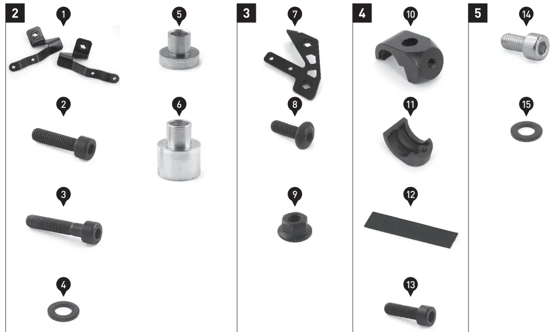
PARTS LIST
| READ AND SAVE THESE MOUNTING INSTRUCTIONS | |||||
| Schiff Step | Nr. No. | Art-Nr./ Bezeichnung a Item No. / Description a | Part | AnzeMb Quantity b | N.m` |
| 2 | (1) | KFT.08.922.001 L / R | Mounting Tab; left / right | 2 /2 | |
| (2) | M8 x 30; DIN 912 | Hexagon Socket Screw; black | 2 /2 | 18 | |
| (3) | M8 x 40; DIN 912 | Hexagon Socket Screw; black | 2 /2 | 18 | |
| (4) | co 8,4; DIN 125 | Washer; black | 4 /6 | ||
| (5) | KFT.08.722.002 | Stepped Spacer; height 5 mm | 2 /2 | ||
| 16) | KFT.08.722.003 | Stepped Spacer; height 13 mm | 2 /2 | ||
| 3 | 17) | KFT.08.922.002L / R | Mounting Tab; left / right | 2 /2 | |
| 18) | M6 x 18; ISO 7380 | Lenshead Screw; black | 4 /6 | 10 | |
| (9) | M6; DIN 6927 | Lock Nut with Flange; black | 4 /6 | ||
| 4 | (101 | SBL.00.051.009 | Clamp | 2/2 | |
| 111) | SBL.00.051.008 | Clamp; backpart | 2 /2 | ||
| (121 | SST.0740.0260.0020 | Protection Strip; length 74 mm | 2 /2 | ||
| (13) | M6 x 20; DIN 912 | Hexagon Socket Screw; black | 2 /2 | 8 | |
| 5 | (141 | M8 x 16; DIN 912 | Hexagon Socket Screw | 2 /2 | 18 |
| (15) | 0 8,4; DIN 125 | Washer; black | 2 /6 | ||

Note: a All measurements in millimeters. b The second number indicates the total quantity of the part in the delivery.
C No torque specifications: Use the torque defined by vehicle manufacturer! The standard torque in this table can be used as long as it is within the vehicle manufacturer’s specifications.
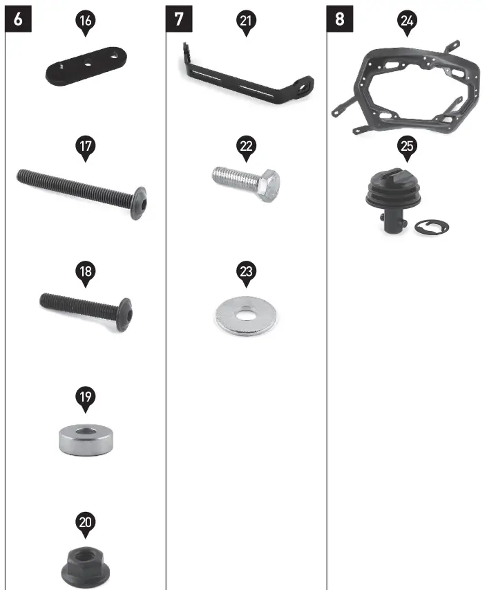
| PARTS LIST • READ AND SAVE THESE MOUNTING INSTRUCTIONS | ||||
| Nr. No. | Art.-Nr. / Bezeichnung a Item No. / Descriptions | Part | Anzaht b Quantity b | •N rn` |
| (16) | KFT.08.922.003 | Relocation Plate | 1 /1 | |
| (17) | M6 x 55; ISO 7380 | Lenshead Screw; black | 1 ti | 8 |
| (18) | M6 x 35; ISO 7380 | Lenshead Screw; black | 2 /2 | 8 |
| (19) | 0 16/o 6,4/h 6 | Spacer | 2 /2 | |
| (20) | M6; DIN 6927 | Lock Nut with Flange; black | 2 to | |
| (21) | KFT.22.892.004 | Crossbar | 1 ii | |
| (22) | M6 x 20; DIN 933 | Hexagon Screw | 2 n | 6 |
| (23) | 0 6,4; DIN 9021 | Washer | 2 /2 | |
| (24) | KFT.08.922.971.01 / 972.01 | Side Carrier; left / right | 2 /2 | |
| (25) | SV.ST.095.501.LK.02 | Quick Fastener with Lock Washer | 8 /8 | |
Note: a All measurements in millimeters. b The second number indicates the total quantity of the part in the delivery.
C No torque specifications: Use the torque defined by vehicle manufacturer! The standard torque in this table can be used as long as it is within the vehicle manufacturer’s specifications.
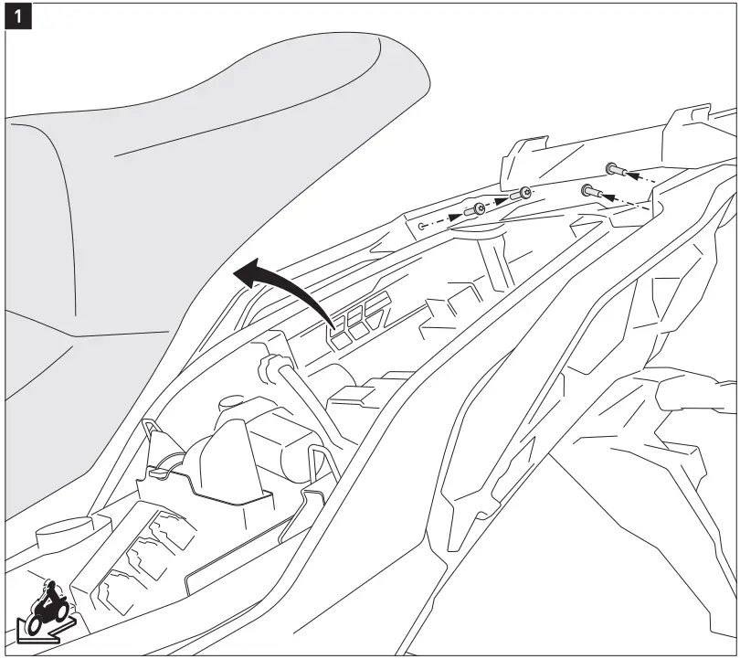
MOUNTING
![]() WARNING: Always wear eye and hand protection!
WARNING: Always wear eye and hand protection!![]() WARNING: Always use appropriate tools! Remove the seatbench as well as the shown screws from the vehicle.
WARNING: Always use appropriate tools! Remove the seatbench as well as the shown screws from the vehicle.
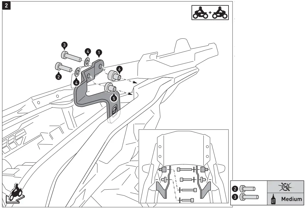
Attach the mounting tabs on both sides to the passenger grips.![]() WARNING: Use liquid thread locker! Do not fully tighten the screws yet.
WARNING: Use liquid thread locker! Do not fully tighten the screws yet.
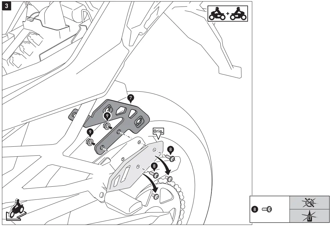
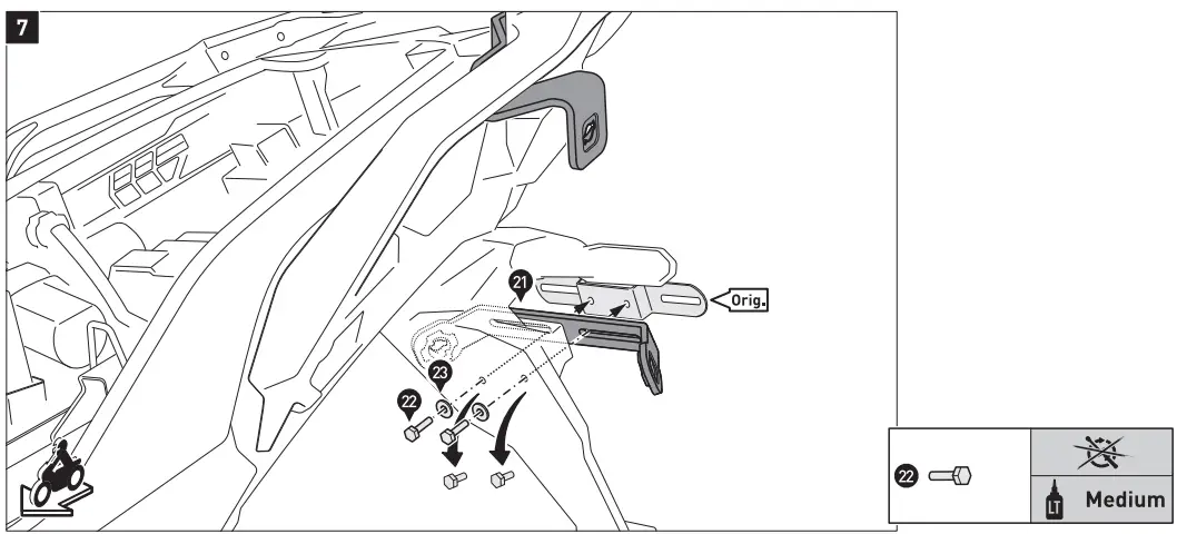
Remove the heel guards on both sides of the vehicle and reattach them with the mounting tabs (7) to the footrest mounts. Do not fully tighten the screws yet.
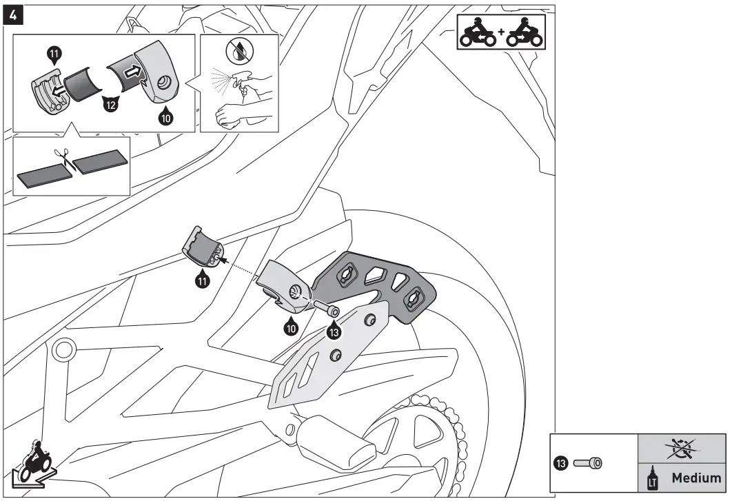
Clean the surfaces on the inner sides of the clamps (10) and (11) thoroughly from grease and dirt residue. Cut the protection strips (12) in half and affix them on the clamps. Attach the clamps onto the vehicles’ frame.![]() WARNING: Use Liquid thread Locker! Do not fully tighten the screws yet.
WARNING: Use Liquid thread Locker! Do not fully tighten the screws yet.
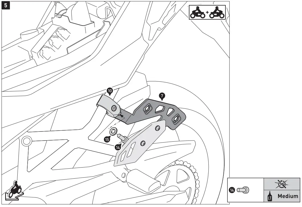
Attach the mounting tabs (7) on both sides of the vehicle to the clamps (10). A WARNING: Use Liquid thread Locker! Do not fully tighten the screws yet.
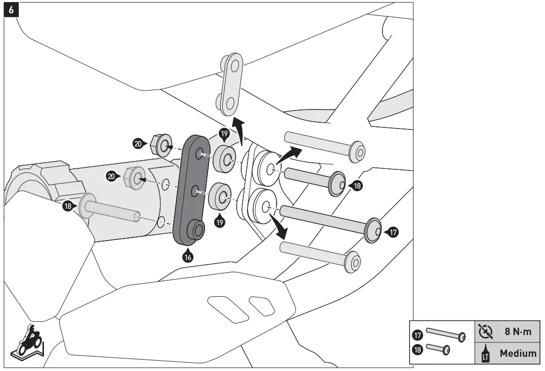
Remove the original mounting plate and the screws of the shock absorber adjuster. Attach the shock absorber adjuster with the relocation plate (16) to the vehicle.![]() WARNING: Use liquid thread locker! Tighten the screw (17) and (18) as specified.
WARNING: Use liquid thread locker! Tighten the screw (17) and (18) as specified.
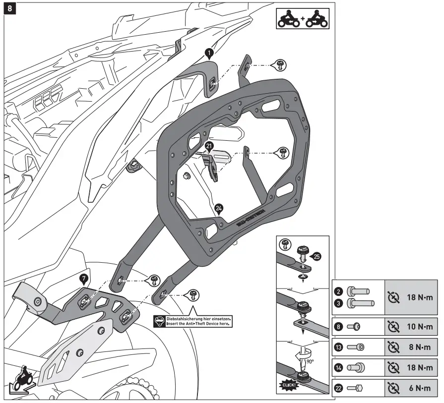
Use the quick fasteners (251 to connect the side carriers (241 to the mounting tabs (1) and (71, as well as the crossbar (21). Secure the quick fasteners with the lock washers. Once all parts are positioned without excess tension, tighten the screws as specified. Finally reattach the seatbench.![]() NOTICE: The Anti-Theft Device is sold seperately.
NOTICE: The Anti-Theft Device is sold seperately.
PRODUCT SPECIFIC INFORMATION
| Maximum Load | Maximum Speed |
![]() WARNING: The indicated maximum load is inclusive the weight of case/luggage and adapter kit. The maximum vehicle load specified by the manufacturer must not be exceeded!
WARNING: The indicated maximum load is inclusive the weight of case/luggage and adapter kit. The maximum vehicle load specified by the manufacturer must not be exceeded!![]() NOTICE: The side carriers are designed exclusively for the use of SW-MOTECH Adapter Kits.
NOTICE: The side carriers are designed exclusively for the use of SW-MOTECH Adapter Kits.![]() NOTICE: Dismount the side carriers when travelling without cases/luggage. Always use the side carriers in pairs.
NOTICE: Dismount the side carriers when travelling without cases/luggage. Always use the side carriers in pairs.![]() WARNING: Make sure that after attaching the luggage to the vehicle it is NOT in the exhaust flow! Dangers of burns!
WARNING: Make sure that after attaching the luggage to the vehicle it is NOT in the exhaust flow! Dangers of burns!![]() NOTICE: Observe the country-specific regulations concerning vehicle registration/operation as well as TUV regulations if applicable. If required, register installed parts in the vehicle documents through an appropriate inspection authority.
NOTICE: Observe the country-specific regulations concerning vehicle registration/operation as well as TUV regulations if applicable. If required, register installed parts in the vehicle documents through an appropriate inspection authority.
![]()
SW-MOTECH GmbH & Co. KG
Ernteweg 7-10
35282 Rauschenberg Germany
Tel. / phone + 49 (0)6425 / 8168 – 050
Fax / fax + 49 (0)6425 / 8168 – 10
[email protected]
www.sw-motech.com
Copyright by SW-MOTECH GmbH & Co. KG Errors and omissions expected.
Technical and design-modifications are subjects to change.


