LS ELECTRIC SV-iG5A Series Device Net Communication Module
Product Information
The iG5A Series Device Net Communication Module is a power module that facilitates Device Net communication. It is supplied from the inverter and has an input voltage of 11-25V DC with a maximum current consumption of 60mA. The communication module supports bus topology and has a maximum number of 64 nodes (including Master) with communication baud rates of 125kbps, 250kbps, and 500kbps. The device supports explicit peer-to-peer messaging, faulted node recovery, Master/Scanner (Predefined M/S Connection), and polling. It also has a terminal resistor with a resistance of 120 ohm and lead type of 1/4W.
Product Usage Instructions
- Always follow the safety precautions mentioned in the manual to prevent accidents and potential hazards from occurring.
- When handling the CMOS components of the communication module, be cautious as static may lead to malfunctioning of the product.
- Turn off the inverter power before changing the communication cable to avoid damaging the module or causing communication errors.
- Precisely insert the Communication module connector to the inverter to avoid damaging the module or causing communication errors.
- Check the parameter unit before setting up the parameter to avoid communication errors.
- Read the operating instructions carefully to fully understand the functions of the SV-iG5A series and to use it properly.
- Refer to Chapter 4 in the manual for installation instructions, including control terminal specifications and instructions for installation.
- Refer to Chapter 5 for LED display information, including NS LED status, MS LED status, and LED tips.
- Refer to Chapter 6 for EDS (Electronic Data Sheets) file information, including Fieldbus ID, Fieldbus Baudrate, Fieldbus LED, and In Instance/Out Instance.
- Refer to Chapter 8 for the definition of Object Map, including Class 0x01 (Identity Object) Instance 1, Class 0x03 (Device Net Object) Instance 1, and Class 0x04 (Assembly Object).
Safety Instructions
- Use this board after read Safety Instruction of this manual carefully before using and follow the instructions exactly,
- Please hand this user manual to end user and trouble shooting manager
- After read this manual, keep it at handy for future reference.
Thank you for purchasing iG5A Series DeviceNet Communication Module
SAFETY PRECAUTIONS
- Always follow safety instructions to prevent accidents and potential hazards from occurring.
- Safety precautions are classified into “WARNING” and “CAUTION” and their meanings are as follows:
WARNING: Improper operation may result in serious personal injury or death.
CAUTION: Improper operation may result in slight to medium personal injury or property damage
- The indicated illustrations on the product and in the manual have the following meanings.
- Danger may be present. Read the message and follow the instructions carefully.
- Particular attention should be paid because danger of an electric shock may be present.
- Keep operating instructions handy for quick reference.
- Read the operating instructions carefully to fully understand the functions of the SV-iG5A series and to use it properly.
CAUTION
- Be cautious, when handling the CMOS components of the communication module.
Static may lead to malfunctioning of the product. - Turn off the inverter power, when changing the communication cable. Otherwise, you may damage the module or a communication error may occur.
- Make sure to insert the Communication module connector to the inverter precisely.
Otherwise, you may damage the module or a communication error may occur. - Check the parameter unit before setting up the parameter.
Otherwise, a communication error may occur.
Introduction
iG5A Device Net communication module connects the iG5A inverter with the Device Net network. Device Net communication module enables the control and monitoring of inverter to be controlled by sequence program of PLC or Master module selected optionally. As one or more inverters are connected and operated with a communication line, it reduces the installation cost compared with when communication is not used. Furthermore, simple wiring enables to the reduction of installation period and easy maintenance as well. A variety of peripheral devices such as PLC, etc. can be used to control the inverter, and factory automation is made easily by its advantage of the fact that it can be operated linked with a variety of systems such as PC, etc.
Device Net Communication Module Specification
| Terminology | Description | |
| Power Supply | Device Net communication module power source | Supplied from inverter |
| Exterior Power Source | Input Voltage : 11 ~25V DC Current consumption: Max. 60mA | |
| Network Topology | Bus Topology | |
| Communication Baudrate | 125kbps, 250kbps, 500kbps | |
| Max. Number of Nodes | 64 nodes (including Master) In the event 1 Master node is connected to Network, the maximum number of the nodes connected is 63 nodes (64-1). | |
| Device Type | AC Drive | |
| Kind of Support Communication | Explicit Peer to Peer Messaging Faulted Node Recovery(Off-Line) Master/Scanner (Predefined M/S Connection) Polling | |
| Terminal Resistor | 120 ohm 1/4W Lead Type | |
Communication Cable Specification
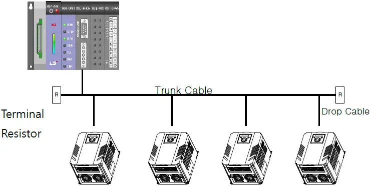 For Device Net Communication, Device Net standard cable specified by ODVA should be used. There are Thick or Thin type cable as DeviceNet standard cable. For Device Net standard cable, refer to ODVA Homepage (www.odva.org).
Either Thick or Thin cable can be used for Trunk Cable, but please use Thick Cable in general. In case of Drop Cable, Thin Cable is strongly recommended. Maximum length of cable as below is the performance when Device Net standard cable was used.
| Baudrate | Trunk Cable Length | Drop Length (Thin Cable) | ||
| Thick Cable | Thin Cable | Max. | Total Sum | |
| 125 kbps | 500 m (1640 ft.) | 100 m (328 ft.) | 6 m (20 ft.) | 156 m (512 ft.) |
| 250 kbps | 250 m (820 ft.) | 78 m (256 ft.) | ||
| 500 kbps | 100 m (328 ft.) | 39m (128ft.) | ||
DeviceNet Cable Colors and Signals
| Name | Color | Description |
| V- | BLACK | Common |
| CAN_L | BLUE | Signal Low |
| S | UNINSULATED | Shield |
| CAN_H | WHITE | Signal High |
| V+ | RED | Power Supply |
Installation
The Contents
When unpacking Device Net communication module box, the contents consist of iG5A Device Net communication module, Pluggable 5-pin connector, Lead Type terminal resistor 120Ω (1/4W), bolt that fastens iG5A Device Net communication module to iG5A inverter, and this manual for Device Net.
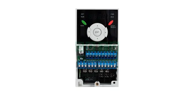
Layout of Device Net communication module
Layout of Device Net communication module is as below. 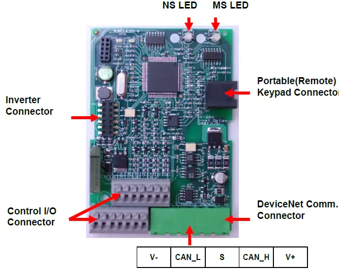 DeviceNet communication terminal specification
| Name | Color | Description |
| V- | BLACK | Common |
| CAN_L | BLUE | Signal Low |
| S | UNINSULATED | Shield |
| CAN_H | WHITE | Signal High |
| V+ | RED | Power Supply |
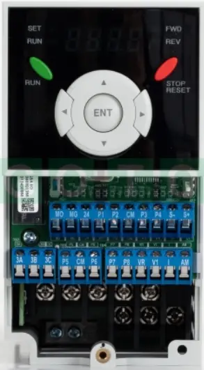
Control terminal specification
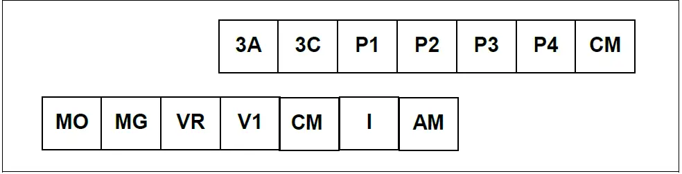
| Terminal | Terminal Description | Specification | ||
| P1 ~ P4 | Multi-function input T/M 1-4 | |||
| CM | Common Terminal | |||
| VR | Power supply for external potentiometer | Output voltage : 12V Max output current : 10mA Potentiometer : 1 ~ 5kohm | ||
| V1 | Input terminal operation | for | Voltage | Max input voltage : -10V ~ +10V input |
| I | Input terminal operation | for | Current | 0 ~ 20mA input Internal resistor : 250 ohm |
| AM | Multi-function analog output terminal | Max output voltage : 11[V] Max output current : 10mA | ||
| MO | Multi-function terminal for open collector | Below DC 26V,100mA | ||
| MG | Ground terminal for external power supply | |||
| 3A | Multi-function relay output A contact | Below AC 250V, 1A | ||
| 3C | Common for Multi-function relays | |||
Note: Tie the control wires more than 15cm away from the control terminals. Otherwise, it interferes front cover reinstallation.
- Use Copper wires rated 600V, 75 ℃ and higher.
Installation of Device Net communication module
- Take off the upper cover (②, ③) from the dedicated inverter for communication and then install the communication module (④) on the inner cover of the inverter (⑤).
- After installation of communication module (④) and then install the upper cover on the inverter.
- Connect the communication and I/O signal cable to control the inverter.
- On completion of basic connection, install the upper cover (③) on the inverter.
- Please use the Portable Keypad (⑥) or Remote Keypad for panel mounting since this communication module is Non Loader type.
Step 1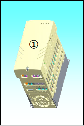 Step 2
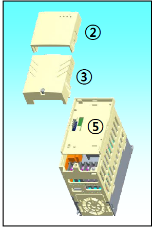 Step 3
 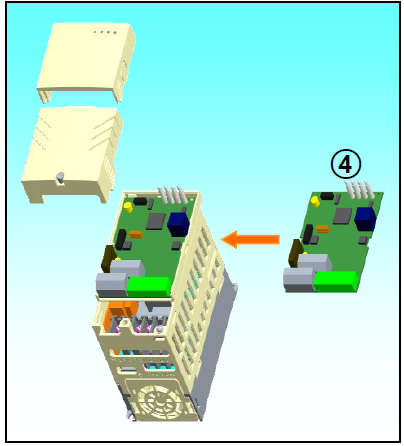 Step 4
 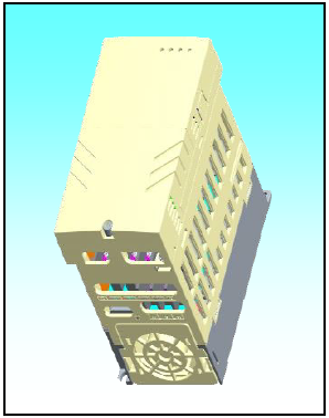 Step 5
 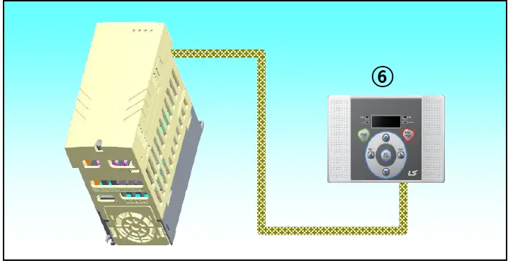 Instruction for installation
- Don’t install or remove Device Net communication module with the power on.
It may cause damages to both Device Net communication module and inverter. Be sure to install or remove Device Net communication module after the current of Inverter condenser has been completely discharged. - Don’t change the connection of communication signal line with the power of inverter on.
- Be sure to connect the inverter body and Communication module connector exactly corresponded with each other.
- In the event of connecting Communication power source (24P, 24G), be sure to check they are V-(24G), V+(24P) Silk of Device Net communication module before connecting them.
- When configuring the Network, be sure to connect the terminal resistor to the device that is connected with the far end part. Terminal resistor should be connected between CAN_L and CAN_H. The value of terminal resistor is 120 ohm 1/4W.
- Dedicated iG5A inverter for communication must be used to use iG5A Device Net communication option module.
- The software for iG5A is supported from version 2.3. (The version of software can be checked through the parameter H79 of FUN2 group)
LED Display
Device Net communication module enclose 2 LEDs mounted; MS (module Status) LED and NS (Network Status) LED. Fundamental function of two LEDs is as below.
| MS LED (Module Status) | It is used to check whether the power source state of Device Net communication module is stable; whether CPU of Device Net communication module is regularly operating; whether interface communication between Device Net communication module and inverter body is made in smooth manner. All the operations as above are normally made, MS LED will be lit in Solid Green |
| NS LED (Network Status) | It is used to show the connection of Device Net communication module to communication on the Network or the network power source status. |
NS LED Status
| LED | State | Cause | Corrective Actions |
| Off | Off-Line (No Power) | 5V power is not energized in Device Net communication module. | Check if the power of inverter is on. Check 5V power is energized in Device Net communication module. |
| Duplicate MAC ID address checking | In case of the power is energized in Device Net communication module, LED turns Off for 5 seconds while the module is checking duplicated MAC ID address. | ||
| Flashing Green | On-Line Not Connected | Cloned node verification is checked, communication environment is ready, but they are not connected with any node | Normal operation before the user attempts the connection |
| Solid Green | On-Line, Connected (Link OK) | Connection of one EMC or more is set up | I/O Communication (Poll) Connection available |
| Flashing Red | Connection Time-Out Critical Link Failure. | Timed out occurred during Poll I/O Communication | [Slave] Inverter Make the comm. update(C99) [Master] PLC Make the reset to Identity Object and then reconnect I/O. |
| Solid Red | Abnormal Condition | Failure of verifying cloned MAC ID | Change MAC ID set up |
| Bus Off Status | Check if the signal line is successfully connected. | ||
| Network power to be energized through Device Net connector is not supplied | Check if network cable is properly connected. Check the operation of Network power supply device. |
| Greenè Flashing Red | Self-test | Device under self-test | Wait for a moment |
| Redè Flashing Green | Communication Fault | After the failure of passing Network Access, it falls under Communication Fault Status. This is the case when Identity Communication Faulted Request Message is received | Normal response |
MS LED Status
| LED | State | Cause | Corrective Actions |
| Off | No Power | 5V power is not energized in Device Net communication module. | Check if the power of inverter is on. Check 5V power is energized in Device Net communication module. |
| Solid Green | Operational | In normal operation | – |
| Solid Red | Unrecoverable Fault | Interface between Device Net communication module and inverter is not made in smooth manner. | Check if Device Net communication module and inverter are connected successfully. |
| Flashing Green & Red | Self Test | Device Net communication module under self test. | – |
LED Tip
In the event that Reset occurs
- MS (module Status) LED glows in Green-Red at every 0.5 second at the beginning, but when the Interface communication between Device Net communication module and inverter comes to normal state, it becomes solid Green.
- Then, NS (Network Status) LED flashes in Green-Red at every 0.5 second.
- In the event there is no abnormality as result of checking the redundant MAC ID, Network Status LED flashes in Green. It means this Device communication module is connected to the Network in normal way, but communication is not made with any Device.
- If it fails to run as above, please check any of the following three cases. If it runs in normal way, you may disregard the following cases.
- If the interface communication between Device Net communication module and inverter doesn’t run in normal way, MS (module Status) LED becomes solid Red. In this case, be sure to check the connection between inverter and DeviceNet communication module first, and then turn on the Inverter.
- In the event that NS doesn’t flash in Green just keeping Off state, it falls under the case either Network power is not on or the Baudrates of current network and Communication module are not matched. You need to check this point carefully.
- In the event there is abnormality as result of checking the redundant MAC ID, Network Status LED becomes solid Red. In this case, please configure MAC ID at the other value using Keypad.
- In the event that the Communication module is in communication with the other Device, NS (Network Status) LED becomes solid Green.
In the event of EMC (Explicit Message Connection) by Scanner (Master)
- Network Status LED becomes solid Green
If EMC setting is released here, it flashes in Green again after 10 seconds. Once EMC is achieved, I/O Connection is available. In this case, the Network Status LED is still continued. - In the event that no communication is made within the time I/O Connection is set, Time Out occurs, and then Network Status LED flashes in Red. (This Status can be changed into flashing Green again depending on the time setting of EMC.
EDS (Electronic Data Sheets) File
This file includes the information on the parameters of inverter. It is used when the user intends to control the parameters of iG5A through the Device Net Manager program. In this case, it is necessary to install on PC the iG5A-use EDS file that we provide. EDS file can be downloaded at the Homepage of LS ELECTRIC. Paste the downloaded file in the folder for the EDS file via Master Configuration programming tool.
Example) SyCon program for XGT Series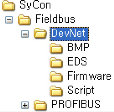 Paste the downloaded file in subfolder ‘EDS’ of DevNet as below figure.
Keypad Parameter associated with Device Net
| Code | Name of Parameter | Default | Range | Description |
| C 1 | Fieldbus Option Name | – | – | When iG5A Device Net communication module is installed, it indicates “dnEt”. |
| drv | Drive Mode | 1. Fx/Rx-1 | 0. Keypad | To command Inverter run with DeviceNet, it requires setting as “4 (Fieldbus)” |
| 1. Fx/Rx-1 | ||||
| 2. Fx/Rx-2 | ||||
| 3. RS485 | ||||
| 4. Fieldbus | ||||
| Frq | Frequency setting method | 0. Keypad-1 | 0. Keypad-1 | To command Inverter frequency with DeviceNet, it requires setting as “9 (Fieldbus)”. |
| 1. Keypad-2 | ||||
| 2. -10~10V | ||||
| 3. 0~10V | ||||
| 4. 0~20mA | ||||
| 5. “2” + “4” | ||||
| 6. “3” + “4” | ||||
| 7. RS485 | ||||
| 8. Digital Volume | ||||
| 9. Fieldbus | ||||
| C 2 | Fieldbus S/W | – | – | Indicates the version of Device Net communication |
| C 3 | Fieldbus | 1 | 0~63 | Inverter ID to be set. |
| C 4 | Fieldbus Baudrate | 125kbps | 125kbps | Requires setting at Baudrate used in the network with which inverter is connected. |
| 250kbps | ||||
| 500kbps | ||||
| C 5 | Fieldbus LED | – | – | Indicates the communication status |
| 70 | Set the value of input instance to be used in Class 0x04 (Assembly Object). As this parameter value is set, the data type to be received (Master- based) at the time of Poll I/O communication is decided. | |||
| 71 | ||||
| 110 | ||||
| C29 | In Instance | 70 | 111 | |
| 141 | ||||
| 142 | ||||
| 143 | ||||
| 144 | ||||
| C30 | Para Status Num | – | – | In the event C29 (In Instance) is set at 141~144, the value of C30 Parameter Status Number is automatically indicated, and this set value of parameter varies depending on the set value of C29. |
| C31 | Para Status-1 | – | 0~0xFFFF | It can be set/display in case of In Instance value between 141 ~ 144. |
| C32 | Para Status-2 | – | 0~0xFFFF | |
| C33 | Para Status-3 | – | 0~0xFFFF | |
| C34 | Para Status-4 | – | 0~0xFFFF | |
| 20 | Set the value of output instance to be used in the Class 0x04 (Assembly Object). As this Parameter value is set, the data type to be sent (Master-based) at the time of Poll I/O communication is decided. | |||
| 21 | ||||
| 100 | ||||
| C49 | Out Instance | 20 | 101 | |
| 121 | ||||
| 122 | ||||
| 123 | ||||
| 124 | ||||
| C50 | Para Ctrl Num | – | – | In the event that C49 (Out Instance) is set at 121~124, the value of C50 (Parameter Control Number) is automatically indicated, and the set value of this Parameter varies depending on the set value of C49. |
| C51 | Para Control-1 | – | 0~0xFFFF | It can be set/display in case of In Instance value between 141 ~ 144. |
| C52 | Para Control-2 | – | 0~0xFFFF | |
| C53 | Para Control-3 | – | 0~0xFFFF | |
| C54 | Para Control-4 | – | 0~0xFFFF | |
| C99 | Comm. Update | 0. No | 0. No 1. Yes | Used when initializing Device Net communication module. In the event of setting C99 at “1 (Yes)”, it carries out initialization and then automatically displays “0 (No)”. |
| I62 | Drive mode select after loss of frequency command | 0. None | 0. None | In case of Device Net communication, it carries out the loss of communication command after the loss of Polling communication Data Command. |
| 1. Free-Run | ||||
| 2. Dec | ||||
| I63 | Wait time after loss of frequency command | 1.0 sec | 0.1~120.0 sec | After I/O connection is disconnected, Lost Command will be occurred after setting time. |
- Run and Frequency command through Device Net have to set to Fieldbus of drv (Run command method) mode and Frq (Frequency command method) mode.
Fieldbus ID (C3)
- Fieldbus ID falls under MAC ID (Media Access Control Identifier) that is called in Device Net.
- As this value is an indigenous value by which each Device is discriminated in Device Net Network, it is not allowed for different Devices to have same values.
- This value is preset as 1 at the factory. In the event that interface communication is in trouble between Device Net communication module and inverter, Default value is automatically changed into “63”.
- In the event of modifying MAC ID during operation, Device Net communication module will be automatically reset. This is because it is essential to check if Device using MAC ID value newly set is on the Network.
- In the event the preset MAC ID value is the one that has already been used by the other Device, NS (Network Status) LED will be changed to solid Red. Here, MAC ID can be changed into the other value using Keypad again. After that, if NS is flashing in green, it means its normal operation.
Fieldbus Baudrate (C4)
- In the event that the communication speed set is not same as that used in the Network, NS LED maintains Off state.
- In the event changing the Baudrate using Keypad, in order for the changed Baudrate value to influence the actual communication speed, it is necessary to send Reset Service to the Identity Object of Inverter through communication or reset the Inverter.
- You may reset the Inverter using C36 (Communication Update).
- In the event that Network Baudrate corresponds with Communication module Baudrate and MAC ID is the only one, NS LED flashes in Green.
Fieldbus LED (C5)
- Device Net communication module has MS LED and NS LED only, but four LEDs are shown from C5 (Fieldbus LED Status) using Keypad. It displays the information of NS LED Red, NS LED Green, MS LED Red and MS LED Green in the order of C5 LEDs (Left Right).
- If C5 is displayed as below, it indicates that currently NS LED is Green and MS LED is Green.
- Example of C5 LED status
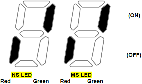
| NS LED Red | NS LED Green | MS LED Red | MS LED Green |
| OFF | ON | OFF | ON |
In Instance, Out Instance (C29, C49)
- In Instance, Out Instance is used in the Poll I/O Data Communication. Poll I/O Connection is the Connection to communicate specific data between Scanner (Master) and Inverter.
- Type of data sent through Poll I/O is decided by the Assembly Instances (C29, C49).
- In case of Instance 20, 21, 100, 101, 70, 71, 110 and 111, the amount of data sent by Poll I/O Communication is 4 Bytes in both directions, and the communication cycle default value is 0 (zero).
- Assembly Instance can be broadly divided into Output and Input based on Scanner. That is, Input Data means the amount of data stored in Scanner. It means the value for inverter to feed back to Scanner. On the contrary, Output Data means the amount of data supplied from Scanner, which is a new command value for Inverter.
- In the event of changing the value of In Instance or Out Instance, Device Net communication module is automatically reset.
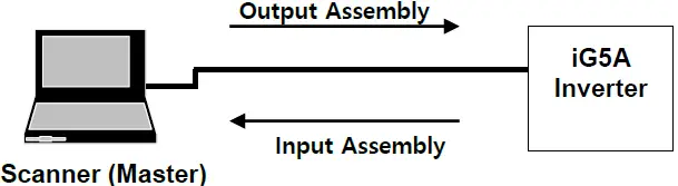
| From the viewpoint of Scanner | From the viewpoint of Inverter | |
| Input Assembly | Receive data | Send data |
| Output Assembly Data | Send data | Receive data |
- In the event of setting C29 (In Instance) at 141 ~ 144, C30 ~ C34 are displayed when C99 (Comm. Update) sets to ‘Yes(1)’.
- In the event of setting C29 (In Instance) at the values other than 141 ~ 144, C7 ~ C11 are not displayed.
- Followings are C30 (Para Status Num) value automatically set and valid Parameter Status with Poll I/O communication depending on the value of In Instance set,.
| In Instance | C30 | C31 | C32 | C33 | C34 |
| 141 | 1 | O | X | X | X |
| 142 | 2 | O | O | X | X |
| 143 | 3 | O | O | O | X |
| 144 | 4 | O | O | O | O |
- Out Instance can be applied in the same way as explained for In Instance.
- In the event of setting C49 (Out Instance) at 121 ~ 124, C50 ~ C54 are displayed when C99 (Comm. Update) sets to ‘Yes(1)’.
- In the event of setting C49 (Out Instance) at the values other than 121~124, C50 ~ C54 are not displayed.
- Followings are C50(Para Ctrl Num) value automatically set and valid Parameter Control with communication depending on the value of Out Instance set.
| Out Instance | C50 | C51 | C52 | C53 | C54 |
| 121 | 1 | O | X | X | X |
| 122 | 2 | O | O | X | X |
| 123 | 3 | O | O | O | X |
| 124 | 4 | O | O | O | O |
Definition of Object Map
DeviceNet communication consists of the assemblies of Objects.
Following terminologies are used to explain the Object of DeviceNet.
| Terminology | Definition |
| Class | Assembly of Objects having similar function |
| Instance | Concrete expression of Object. |
| Attribute | Property of Object. |
| Service | Function supported by Object or Class. |
Followings are the definition of Object used in iG5A DeviceNet.
| Class Code | Object Class Name |
| 0x01 | Identity Object |
| 0x03 | DeviceNet |
| 0x04 | Assembly |
| 0x05 | Connection |
| 0x28 | Motor Data |
| 0x29 | Control Supervisor |
| 0x2A | AC/DC Drive |
| 0x64 | Inverter |
Class 0x01 (Identity Object) Instance 1 (Entire device, host and adapter)
Attribute
| Attribute ID | Access | Attribute Name | Data Length | Attribute Value |
| 1 | Get | Vendor ID | Word | 259 |
| 2 | Get | Device Type (AC Drive) | Word | 2 |
| 3 | Get | Product Code | Word | 10 (Note1) |
| 4 | Get | Revision Low Byte – Major Revision High Byte – Minor Revision | Word | (Note 2) |
| 5 | Get | Status | Word | (Note 3) |
| 6 | Get | Serial Number | Double Word | – |
| 7 | Get | Product Name | 14 Byte | iG5A Device Net |
Note :Product Code 10 means iG5A inverter
- Revision corresponds with the version of Device Net communication module. High Byte means Major Revision, and Low Byte means Minor Revision. For example, 0x0102 means 2.01.
DeviceNet communication module version is displayed in C2 (Fieldbus S/W Version)
| Bit | 0 (Owned) | 8 (Recoverable Minor Fault) | Other Bits |
| Meaning | 0 : Device is not connected to Master 1 : Device is connected to Master | 0 : inverter Interface communication is in normal state 1 : inverter Interface communication is in abnormal state | Not support |
Service
| Service Code | Definition | Support for Class | Support for Instance |
| 0x0E | Get Attribute Single | No | Yes |
| 0x05 | Reset | No | Yes |
Class 0x03 (DeviceNet Object) Instance 1
Attribute
| Attribute ID | Access | Attribute Name | Data Length | Initial Value | Range | Description | |
| 1 | Get/Set | MAC ID (Note 4) | Byte | 1 | 0~63 | Device Net Communication Address Value | |
| 2 | Get | Baudrate (Note5) | Byte | 0 | 0 | 125k bps | |
| 1 | 250k bps | ||||||
| 2 | 500k bps | ||||||
| 5 | Get | Allocation Information (Note 6) | Allocation Choice Byte | Word | – | Bit 0 | Explicit Message |
| Bit1 | Polled | ||||||
| Master’s MAC ID | – | 0~63 255 | Changed with Allocate only | ||||
Note: MAC ID get/set its value in C3 Fieldbus ID.
- Baudrate get/set the value of Fieldbus Baudrate of C4.
- It consists of 1 Word, Upper byte indicates MASTER ID connected and Lower byte indicates the type of communication between Master and Slave. Here, Master means not configuration, it means the device can communicate I/O communication, PLC etc. For reference, in the event of Master is not connected, it indicates 0xFF00 of efault Master ID. There is 2 type of communication type. In case of Explicit communication of non-periodic communication is possible, first bit is 1 and Polled communication of periodic communication is possible, second bit is 1. For example, PLC MASTER is 0 and if communication Explicit and Polled are possible, Allocation Information becomes 0x0003. If Master is not connected, it indicates 0xFF00.
Service
| Service Code | Definition | Support for Class | Support for Instance |
| 0x0E | Get Attribute Single | Yes | Yes |
| 0x10 | Set Attribute Single | No | Yes |
| 0x4B | Allocate Master/Slave Connection Set | No | Yes |
| 0x4C | Release Group2 Identifier Set | No | Yes |
Class 0x04 (Assembly Object)
In Instance 70/110
| Instance | Byte | Bit7 | Bit6 | Bit5 | Bit4 | Bit3 | Bit2 | Bit1 | Bit0 |
| 70/110 | 0 | – | – | – | – | – | Running Fwd | – | Faulted |
| 1 | 0x00 | ||||||||
| 2 | Speed actual (Low byte) Instance 70 – RPM Instance 110 – Hz | ||||||||
| 3 | Speed actual (High byte) Instance 70 – RPM Instance 110 – Hz | ||||||||
Explanation on Instance 70/110
| Byte 0 | Bit0 | Faulted | Signal on the occurrence of inverter Trip 0 : Inverter in normal condition 1 : Occurrence of Inverter Trip |
| Bit2 | Running Fwd | Indicates the information if Inverter runs in forward direction. 0 : Not in forward direction. 1 : In forward direction | |
| Byte 2 Byte 3 | Speed reference | Instance 70 : Indicates the current information on inverter running speed in [rpm] Instance 110 : Indicates the current information on inverter running speed in [Hz] | |
In Instance 71/111
| Instance | Byte | Bit7 | Bit6 | Bit5 | Bit4 | Bit3 | Bit2 | Bit1 | Bit0 |
| 71/111 | 0 | At Ref. | Ref From Net | Ctrl From Net | Ready | Running Rev | Running Fwd | – | Faulted |
| 1 | 0x00 | ||||||||
| 2 | Speed actual (Low byte) Instance 71 – RPM Instance 111 – Hz | ||||||||
| 3 | Speed actual (High byte) Instance 71 – RPM Instance 111 – Hz | ||||||||
Explanation on Instance 71/111
|
Byte 0 | Bit0 | Faulted | Signal on the occurrence of inverter Trip. 0 : Inverter in normal condition 1 : Occurrence of Inverter Trip | ||||
| Bit2 | Running Fwd | Indicates the information forward direction. 0 : Not in forward direction. 1 : In forward direction | if | Inverter | runs | in | |
| Bit3 | Running Rev | Indicates the information reverse direction. 0 : Not in reverse direction. 1 : In reverse direction | if | Inverter | runs | in | |
| Bit4 | Ready | Indicates the status information if Inverter is ready to run. 0 : Inverter is not ready to run 1 : Inverter is ready to run When the power of inverter is ON, this value always becomes 1. | |||||
| Bit5 | Ctrl From Net | Indicates if the current run command source is communication. 0 : In case inverter run is commanded from the other source than communication 1 : In the event inverter run command is from communication, this value becomes 1 if the set value of drv (Drive mode) is Fieldbus. | |||||
| Bit6 | Ref From Net | Indicates if the current frequency command source is communication. 0 : In case inverter frequency command is from the other source than communication 1 : In the event inverter frequency command is from communication, this value becomes 1 if the set value of Frq (Frequency setting method) is Fieldbus. | |||||
| Bit7 | At Ref | Indicates the current frequency reached the Reference frequency. 0 : Current frequency fails to reach Reference frequency. 1 : Current frequency reached Reference frequency | |||||
| Byte 2 Byte 3 | Speed reference | Instance 71 : Indicates the current information on inverter running speed in [rpm]. Instance 111 : Indicates the current information on inverter running speed in [Hz] | |||||
Table of Other Attributes associated with In Instances (70, 71, 110, 111)
| Name | Description | Related Attribute | ||
| Class | Instance | Attribute | ||
| Faulted | Inverter error occurs in interface communication or inverter trips | 0x29 | 1 | 10 |
| Running Fwd | Motor is running in forward direction | 0x29 | 1 | 7 |
| Running Rev | Motor is running in reverse direction | 0x29 | 1 | 8 |
| Ready | Motor is ready to run | 0x29 | 1 | 9 |
| Ctrl From Net | Run/Stop control Signal 1 : Device Net is the inverter run command source | 0x29 | 1 | 15 |
| Ref From Net | Speed control command signal 1 : DeviceNet is the inverter frequency command source | 0x2A | 1 | 29 |
| At Reference | Checks if the current frequency corresponds with the object frequency. 1 : Command frequency is same as the current frequency | 0x2A | 1 | 3 |
| Drive State | Current Motor State | 0x29 | 1 | 6 |
| Speed Actual | Indicates the current run frequency | 0x2A | 1 | 7 |
In Instance 141/142/143/144
When In Instance is set at 141, 142, 143 and 144, Receive (Master-based) Poll I/O Data Information is not fixed, and the address of the data that the user intends to use in COM-31~34 is configured, allowing the user flexibility. In case of using Out Instances of 141, 142, 143 and 144, Device Net communication module sends Master each data in 2Byte, 4Byte, 6Byte and 8Byte. The Byte of the data to be sent is fixed depending on the set value of In Instance. For example, if In Instance is set at 141, it transmits the data in 2Byte. But if In Instance is set at 143, it transmits the data in 6Byte.
| Instance | Byte | Bit7 | Bit6 | Bit5 | Bit4 | Bit3 | Bit2 | Bit1 | Bit0 | |||
| 141 | 0 | Low Byte of the Address set at C31 Para State-1 | ||||||||||
| 1 | High Byte of the Address set at C31 Para State-1 | |||||||||||
| 142 | 2 | Low Byte of the Address set at C32 Para State-2 | ||||||||||
| 3 | High Byte of the Address set at C32 Para State-2 | |||||||||||
| 143 | 4 | Low Byte of the Address set at C33 Para State-3 | ||||||||||
| 5 | High Byte of the Address set at C33 Para State-3 | |||||||||||
| 144 | 6 | Low Byte of the Address set at C34 Para State-4 | ||||||||||
| 7 | High Byte of the Address set at C34 Para State-4 | |||||||||||
Output Instance 20/100
| Instance | Byte | Bit7 | Bit6 | Bit5 | Bit4 | Bit3 | Bit2 | Bit1 | Bit0 |
| 20/100 | 0 | – | – | – | – | – | Fault Reset | – | Run Fwd |
| 1 | – | ||||||||
| 2 | Speed reference (Low byte) Instance 20 – RPM Instance 100 – Hz | ||||||||
| 3 | Speed reference (High byte) Instance 20 – RPM Instance 100 – Hz | ||||||||
Explanation on Instance 20/100
| Byte 0 | Bit0 | Run Fwd | Forward direction run command. 0 : Stop Forward direction run 1 : Forward direction run command |
| Bit2 | Fault Reset | Reset when error occurs. It happens only when inverter trip occurs. 0 : It doesn’t adversely affect the inverter. (You may not be concerned about it) 1 : performs Trip Reset. | |
| Byte 2 Byte 3 | Speed reference | Instance 20 : Commands the inverter speed in [rpm]. Instance 100 : Commands the inverter speed in [Hz]. | |
Output Instance 21/101
| Instance | Byte | Bit7 | Bit6 | Bit5 | Bit4 | Bit3 | Bit2 | Bit1 | Bit0 |
| 21/101 | 0 | – | – | – | – | – | Fault Reset | Run Rev | Run Fwd |
| 1 | – | ||||||||
| 2 | Speed reference (Low byte) Instance 21 – RPM Instance 101 – Hz | ||||||||
| 3 | Speed reference (High byte) Instance 21 – RPM Instance 101 – Hz | ||||||||
Explanation on Instance 21/101
| Byte 0 | Bit0 | Run Fwd | Commands Forward Direction Run. 0 : Stop forward direction run 1 : Forward direction run command |
| Bit1 | Run Rev | Commands Reverse Direction Run. 0 : Stop reverse direction run 1 : Reverse direction run command | |
| Bit2 | Fault Reset | Resets when error occurs. It happens only when inverter trip occurs. | |
| Byte 2 Byte 3 | Speed reference | Instance 21 : In [rpm] è not support. Instance 101 : Commands the inverter speed in [Hz]. | |
Table of Other Attributes associated with In Instance (20, 21, 100, 101)
Name | Description | Related Attribute | ||
| Class | Instance | Attribute ID | ||
| Run Fwd (Note 7) | Forward Run Command | 0x29 | 1 | 3 |
| Run Rev (Note 7) | Reverse Run Command | 0x29 | 1 | 4 |
| Fault reset (Note7) | Fault Reset Command | 0x29 | 1 | 12 |
| Speed reference | Speed Command | 0x2A | 1 | 8 |
Note: Refer to Drive Run and Fault of 8.6 Class 0x29 (Control Supervisor Object)
Out Instance 121/122/123/124
When Out Instance is set at 121, 122, 123 and 124, Send (Master-based) Poll I/O Data Information is not fixed, but the address of the data that the user intends to for C51 ~ C54 is set, giving the user flexibility. At the time of using Out Instance 121, 122, 123 and 124, Device Net communication module receives from Master the data of 2Byte, 4Byte, 6Byte and 8Byte. However, the number of information received is decided depending on the set value of Out Instance. For example, if Out Instance is set at 122, the Device Net communication module receives the data value of 4Byte.
| Instance | Byte | Bit7 | Bit6 | Bit5 | Bit4 | Bit3 | Bit2 | Bit1 | Bit0 | |||
| 121 | 0 | Low Byte of the Address set at C51 Para State-1 | ||||||||||
| 1 | High Byte of the Address set at C51 Para Control1 | |||||||||||
| 122 | 2 | Low Byte of the Address set at C52 Para Control-2 | ||||||||||
| 3 | High Byte of the Address set at C52 Para Control-2 | |||||||||||
| 123 | 4 | Low Byte of the Address set at C53 Para Control-3 | ||||||||||
| 5 | High Byte of the Address set at C53 Para Control-3 | |||||||||||
| 124 | 6 | Low Byte of the Address set at C54 Para Control-4 | ||||||||||
| 7 | High Byte of the Address set at C54 Para Control-4 | |||||||||||
Class 0x05 (DeviceNet Connection Object)
Instance
| Instance | Instance Name |
| 1 | Predefined EMC |
| 2 | Poll I/O |
| 6, 7, 8, 9, 10 | Dynamic EMC |
Attribute
| Attribute ID | Access | Attribute Name | |
| Established/ Timed Out | Established/ Deffered delete | ||
| 1 | Get | Get | State |
| 2 | Get | Get | Instance type |
| 3 | Get | Get | Transport Trigger Class |
| 4 | Get/Set | Get | Produced Connection ID |
| 5 | Get/Set | Get | Consumed Connection ID |
| 6 | Get | Get | Initial Comm Characteristics |
| 7 | Get | Get | Produced Connection Size |
| 8 | Get | Get | Consumed Connection Size |
| 9 | Get/Set | Get/Set | Expected Packet Rate |
| 12 | Get/Set | Get/Set | Watchdog Timeout Action |
| 13 | Get | Get | Produced Connection Path Length |
| 14 | Get | Get | Produced Connection Path |
| 15 | Get | Get | Consumed Connection Path Length |
| 16 | Get | Get | Consumed Connection Path |
| 17 | Get/Set | Get | Production Inhibit Time |
Service
| Service Code | Definition | Support for Class | Support for Instance |
| 0x0E | Get Attribute Single | No | Yes |
| 0x05 | Reset | No | Yes |
| 0x10 | Set Attribute Single | No | Yes |
Class 0x28 (Motor Data Object) Instance
Attribute
| Attribute ID | Access | Attribute Name | Range | Definition |
| 3 | Get | Motor Type | 7 | Squirrel-cage induction motor (Fixed Value) |
| 6 | Get | Motor Rated Current | 0~0xFFFF | [Get] Reads Cur (Motor rated current) Value. |
| 7 | Get | Motor Rated Voltage | 0~0xFFFF | [Get] Reads Motor Rated Voltage Value |
Service
| Service Code | Definition | Support for Class | Support for Instance |
| 0x0E | Get Attribute Single | No | Yes |
| 0x10 | Set Attribute Single | No | Yes |
Class 0x29 (Control Supervisor Object) Instance 1
| Attribute ID | Access | Attribute Name | Initial Value | Range | Definition |
| 3 | Get / Set | Forward Run Cmd. | 0 | 0 | Stop |
| 1 | Forward Direction Run | ||||
| 4 | Get / Set | Reverse Run Cmd. | 0 | 0 | Stop |
| 1 | Reverse Direction Run | ||||
| 5 | Get | Net Control | 0 | 0 | Run Command with the Source other than Device Net communication |
| 1 | Run Command with DeviceNet communication Source | ||||
| 6 | Get | Drive State | 3 | 0 | Vendor Specific |
| 1 | Startup | ||||
| 2 | Not Ready (State of resetting) | ||||
| 3 | Ready (State of Stopping) | ||||
| 4 | Enabled (Acceleration, Constant speedd) | ||||
| 5 | Stopping (State of Stopping) | ||||
| 6 | Fault Stop | ||||
| 7 | Faulted (Trip Occurred) | ||||
| 7 | Get | Running Forward | 0 | 0 | State of Stopping |
| 1 | State of running in forward direction | ||||
| 8 | Get | Running Reverse | 0 | 0 | State of Stopping |
| 1 | State of running in reverse direction | ||||
| 9 | Get | Drive Ready | 1 | 0 | State of resetting or Trip occurred. |
| 1 | Normal condition where inverter can run | ||||
| 10 | Get | Drive Fault | 0 | 0 | State that Trip doesn’t occur at present |
| 1 | State that Trip occurred at present. Falls under the case of Latch Trip | ||||
| 12 | Get / Set | Drive Fault Reset | 0 | 0 | |
| 1 | Trip Reset to release trip after the occurrence of Trip | ||||
| 13 | Get | Drive Fault Code | 0 | Refer to the Table of Drive Fault Code as below | |
| 14 | Get | Control From Net. | 0 | 0 | Run Command with the Source other than Device Net communication |
| 1 | Run Command with Device Net communication Source |
Inverter Operation with Forward Run Cmd. and Reverse Run Cmd.
| Run1 | Run2 | Trigger Event | Run Type |
| 0 | 0 | Stop | NA |
| 0 è 1 | 0 | Run | Run 1 |
| 0 | 0 è 1 | Run | Run 2 |
| 0 è 1 | 0 è 1 | No Action | NA |
| 1 | 1 | No Action | NA |
| 1 è 0 | 1 | Run | Run2 |
| 1 | 1 è 0 | Run | Run1 |
In the above table, Run1 indicates Forward Run Cmd. And Run 2 indicates Reverse Run Cmd. That is, Communication module will be command to inverter at the moment that the status is changed from 0 (FALSE) to 1 (TRUE). The value of Forward Run Cmd. indicates the value of Communication module Run Command not current status of inverter run.
- Drive Fault
Drive Fault becomes TRUE when Inverter has a Trip. Drive Fault Codes are as follows.
- Drive Fault Code
| Fault Code | Description |
| 0x0000 | None |
| 0x1000 | ERR POT IOL (Communication Error) ( Output Phase Loss) (Inverter Overload) COL(Input Phase Loss) EEP(Parameter Saver Error) NBR(Brake Control Error) ETH(Electronic Thermal) COM(Keypad Error) |
| 0x2200 | OLT (Overload Trip) |
| 0x2310 | OCT (OverCurrent) |
| 0x2330 | GFT (Ground Fault Current) |
| 0x2340 | OC2 (Overcurrent2) |
| 0x3210 | OVT (Over Voltage) |
| 0x3220 | LVT (Low Voltage) |
| 0x4000 | NTC (NTC Open) |
| 0x4200 | OHT (Inverter OverHeat) |
| 0x5000 | HWT (Hardware Fault) |
| 0x7000 | FAN (Cooling Fan Fault) |
| 0x9000 | ETA & ETB (External Fault) EST (Instant Cut off) |
Drive Fault Reset
Inverter commands TRIP RESET when Drive Fault Reset is becomes 0 -> 1; that is FALSE -> TRUE. In the event of 1 (TRUE) command is repeated at 1 (TRUE) status, TRIP RESET command is not valid to inverter Trip. TRIP RESET command can be valid to command 0 (FAULT) at 1 (TRUE) status and then command 1 (TRUE).
Service
| Service Code | Definition | Support for Class | Support for Instance |
| 0x0E | Get Attribute Single | No | Yes |
| 0x10 | Set Attribute Single | No | Yes |
Class 0x2A (AC Drive Object) Instance 1
Attribute
| Attribute ID | Access | Attribute Name | Range | Definition |
| 3 | Get | At Reference | 0 | Indicates that output frequency didn’t reach the set frequency. |
| 1 | Indicates that output frequency reached the set frequency | |||
| 4 | Get | Net Reference | 0 | Frequency command source is not Fieldbus communication. |
| 1 | Frequency command source is not Fieldbus communication. | |||
| 6 | Get | Drive Mode | 0 | Vendor Specific Mode (note10) |
| 1 | Open Loop Speed (Frequency) | |||
| 2 | Closed Loop Speed Control (note10) | |||
| 3 | Torque Control (note10) | |||
| 4 | Process Control (e.g. PI) | |||
| 7 | Get | Speed Actual | 0~24000 (rpm) | Indicates the value of current output frequency converted into [rpm]. |
| 8 | Get / Set | Speed Ref | 0~24000 (rpm) | Commands the target frequency in [rpm] unit. It can be applied with the setting 4.Fieldbus of drv (Run Ref src). Range Error will be occurred when speed command is set larger than MAX. Frequency of inverter. |
| 9 | Get | Actual Current | – | Performs monitoring of the present current at every 0.1 A. |
| 29 | Get | Ref. From Network | 0 | Frequency command source is not Device Net communication |
| 1 | Frequency command source is Device Net communication. | |||
| 100 | Get | Actual Hz | 0~400.00 (Hz) | Performs monitoring of the current run frequency (in Hz) |
| 101 | Get / Set | Reference Hz | 0~400.00 (Hz) | Command frequency can be set by communication when Freq Ref Src is set 9.Fieldbus. Range Error will be occurred when speed command is set larger than MAX. Frequency of inverter. |
| 102 | Get / Set | Acceleration Time ( Note 8) | 0~6000.0 (sec) | Setting/Monitoring of Inverter acceleration time |
| 103 | Get /Set | Deceleration Time ( Note 9) | 0~6000.0 (sec) | Setting/Monitoring of Inverter deceleration time |
Note: It is related with ACC of DRV Group.
- It is related with ACC of dEC Group.
- It is not support in iG5A inverter.
Service
| Service Code | Definition | Support for Class | Support for Instance |
| 0x0E | Get Attribute Single | Yes | Yes |
| 0x10 | Set Attribute Single | No | Yes |
Class 0x64 (Inverter Object) – Manufacture Profile
Attribute
| Instance | Access | Attribute Number | Attribute Name | Attribute Value |
| 2 (Drive Group) | ||||
| 3 (Function Group1) | Get/Set | Identical with iG5A Manual Code | iG5A Keypad Title (Refer to iG5A Manual) | Setting range of iG5A Parameter (Refer to iG5A Manual) |
| 4 (Function Group2) | ||||
| 5 (I/O Group) | ||||
| 6 (Comm. Group) |
Service
| Service Code | Definition | Support for Class | Support for Instance |
| 0x0E | Get Attribute Single | Yes | Yes |
| 0x10 | Set Attribute Single | No | Yes |
- Read Only which is the parameter attribute of inverter is not support the Set Service.
Warranty
| Maker | LS ELECTRIC Co., Ltd. | Installation Date | ||
| Model No. | SV-iG5A Device Net Communication Module | Warranty Period | ||
| Customer Information | Name | |||
| Address | ||||
| Tel. | ||||
| Sales Office (Distributor) | Name | |||
| Address | ||||
| Tel. | ||||
Warranty period is 12 months after installation or 18 months after manufactured when the installation date is unidentified. However, the guarantee term may vary on the sales term.
IN-WARRANTY service information
If the defective part has been identified under normal and proper use within the guarantee term, contact your local authorized LS distributor or LS Service center.
OUT-OF WARRANTY service information
The guarantee will not apply in the following cases, even if the guarantee term has not expired.
- Damage was caused by misuse, negligence or accident.
- Damage was caused by abnormal voltage and peripheral devices’ malfunction (failure).
- Damage was caused by an earthquake, fire, flooding, lightning, or other natural calamities.
- When LS nameplate is not attached.
When the warranty period has expired.


