macnaught AMFM Mechanical Diesel Meter
INTRODUCTION
Thank you for purchasing a Macnaught AMFM Mechanical Diesel Meter.
The AMFM meter is a mechanical nutating disc meter providing a reliable, accurate method of measuring diesel. The meter has two totals available (resettable batch total and non resettable total). Macnaught manufacture a full range of pumps, meters and accessories to suit most of your fluid transfer needs. Please consult your local Macnaught reseller for more information.
Please read and retain this instruction manual to assist you in the operation and maintenance of this quality product.
GENERAL INFORMATION
This manual assists you in operating and maintaining your new Mechanical Diesel Meter. The information contained will help you ensure many years of dependable performance and trouble free operation.
Your in-line nutating meter is designed to accurately measure low viscosity fluids and water. This nutating disc meter is ideal for use on low pressure in-line applications, mobile installations and electric diesel pumps, generally fitted close to the dispensing nozzle.
 CAUTION
Observe precautions against fire or explosion when dispensing flammable liquid. Do not operate the meter in the presence of any source of ignition including running or hot engines, lighted cigarettes or gas or electric heaters. Ensure that you follow all the correct earthing and grounding procedures before use.
Inspect seals and connections for leaks weekly when using flammable liquids.
Do not use Teflon tape on any connections when using flammable liquid.
Do not use this meter with gasoline or any fluid other than the compatible fluid specified in this manual.
Do not use the meter above the maximum pressure of 3.5 bar.
OPERATION
Both the batch total and accumulative total will turn simultaneously when fluid passes through the meter. Turn the reset knob to reset the batch total to zero.
INSTALLATION
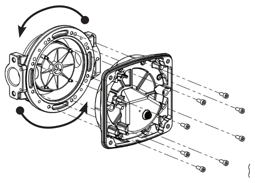
The meter has been manufactured for standard horizontal fitting with a flow direction from left to right. The orientation can be changed using the following procedure.
- Remove the 4 screws that hold meter cover.
- Remove the 2 screws that hold register.
- Remove the 8 screws that hold meter aluminium top.
- Turn the body to the desired location, ensure you do not damage the sealing body o-ring.
- Tighten the 8 screws that hold meter aluminium top, do not exceeds max torque of 4,5 Nm.
- Carefully fit the register to the meter body, ensure you do not bend the pinion shaft.
- Tighten the 2 screws that hold register, do not exceeds max torque of 2 Nm.
- Carefully place the meter cover.
- Tighten the 4 screws that hold meter cover, do not exceeds max torque of 2 Nm.

NOTE: When fitting meter, ensure direction of flow is the same as the arrow cast to underside of the meter. Macnaught recommends that a filter screen of at least 40 mesh is installed prior to the flow meter. Macnaught has a HA1S (10 micron) fuel filter available if required.
DO NOT exceed a maximum pressure of 3.5 bar (50psi).
METER FIEL CALIBRATION
Calibration may be required depending on installation or after disassembly, metering different fluids or where meter wear has occurred.
NOTE: You will need to use an accurate measuring container with graduations up to at least 19 litre capacity.
Calibration procedure
- Set the batch total to Zero
- Dispense 19 liters into your accurate measuring container
- Check the total shown on the meter and compare with the actual total dispensed as shown in the container.
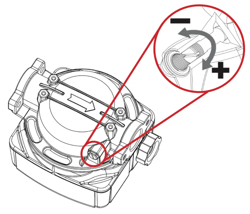
- Adjust the calibration screw as required
a) Turn the screw clockwise to reduce the indicated amount
b) Turn the screw anti-clockwise to increase the indicated amount
NOTE: One full turn of the screw will change the indicated amount approximately 2 liters. - Repeat steps 1 – 4 until meter calibration is acceptable

METER MAINTENANCE
This meter has been designed for minimum maintenance. If you have a problem with the meter please follow the troubleshooting guide in this manual or contact you local Macnaught service center or distributor.
(Register cover removal / replacement)
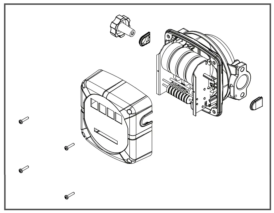
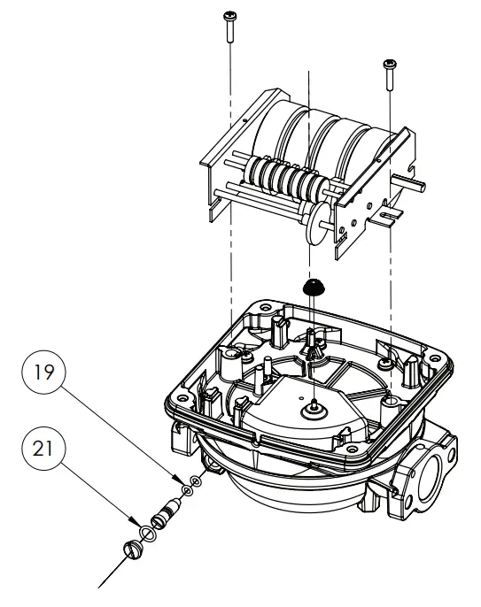
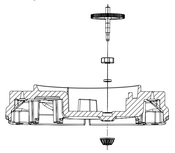
- A) head disassembly, calibration screw, cap and related seals

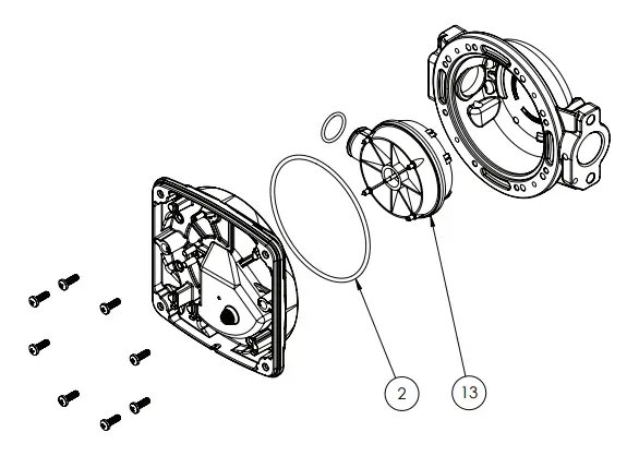
- B) disassembling the flange, body and o-ring chamber

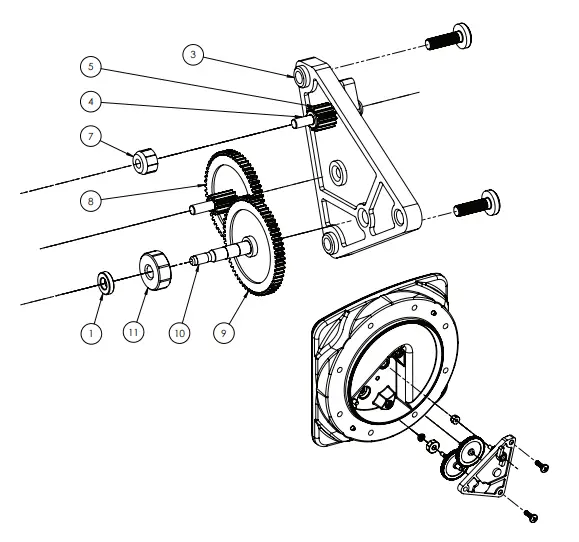
- C) gears and leverism disassembly

- D) conical gear detail

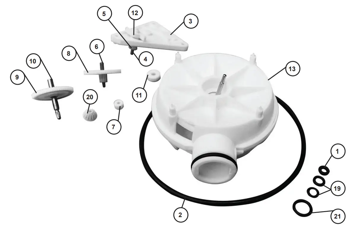
| Item | Description | Q.ty |
| 1 | QUAD-RING | 1 |
| 2 | O-RING 4450 | 1 |
| 3 | GEAR HOLDER | 1 |
| 4 | GEAR WHEEL SHAFT | 1 |
| 5 | GEAR WHEEL | 1 |
| 6 | WHEEL GEAR SHAFT | 1 |
| 7 | SHAFT BUSHING Ø3MM | 1 |
| 8 | GEAR WHEEL Z61-Z11 | 1 |
| 9 | GEAR WHEEL Z62 | 1 |
| 10 | CONIC PINION SHAFT | 1 |
| 11 | BUSHING CONIC SHAFT | 1 |
| 12 | DRAG LEVER | 1 |
| 13 | MEASURE CHAMBER + O-RING | 1 |
| 19 | O-RING 2018 NBR | 2 |
| 20 | Z14 PINION | 1 |
| 21 | O-Ring 108 NBR | 1 |
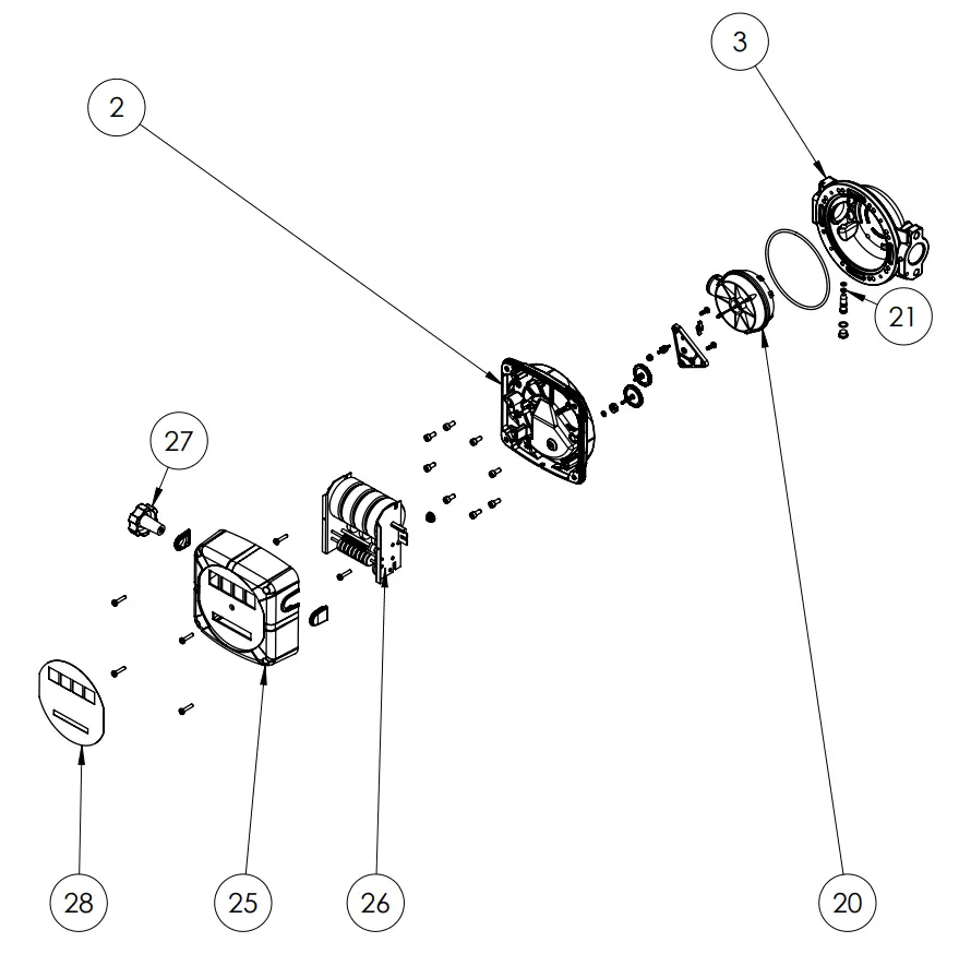
METER PART LIST
| Item | Description | Qty |
| 2 | chamber lid | 1 |
| 3 | meter body | 1 |
| 20 | measure chamber | 1 |
| 21 | adjustment bypass screw | 1 |
| 27 | reset knob | 1 |
| 28 | meter label | 1 |
AVAILABLE ACCESSORIES
| For seal kits: | Order AMFM-1K (for pumps manufactured before Sep 2022) |
| Order AMFM-1K-N (for pumps manufactured after Sep 2022) | |
| For fascia and reset button set: | Order AMFM-2K (for pumps manufactured before Sep 2022) |
| Order AMFM-2K-N (for pumps manufactured after Sep 2022) |
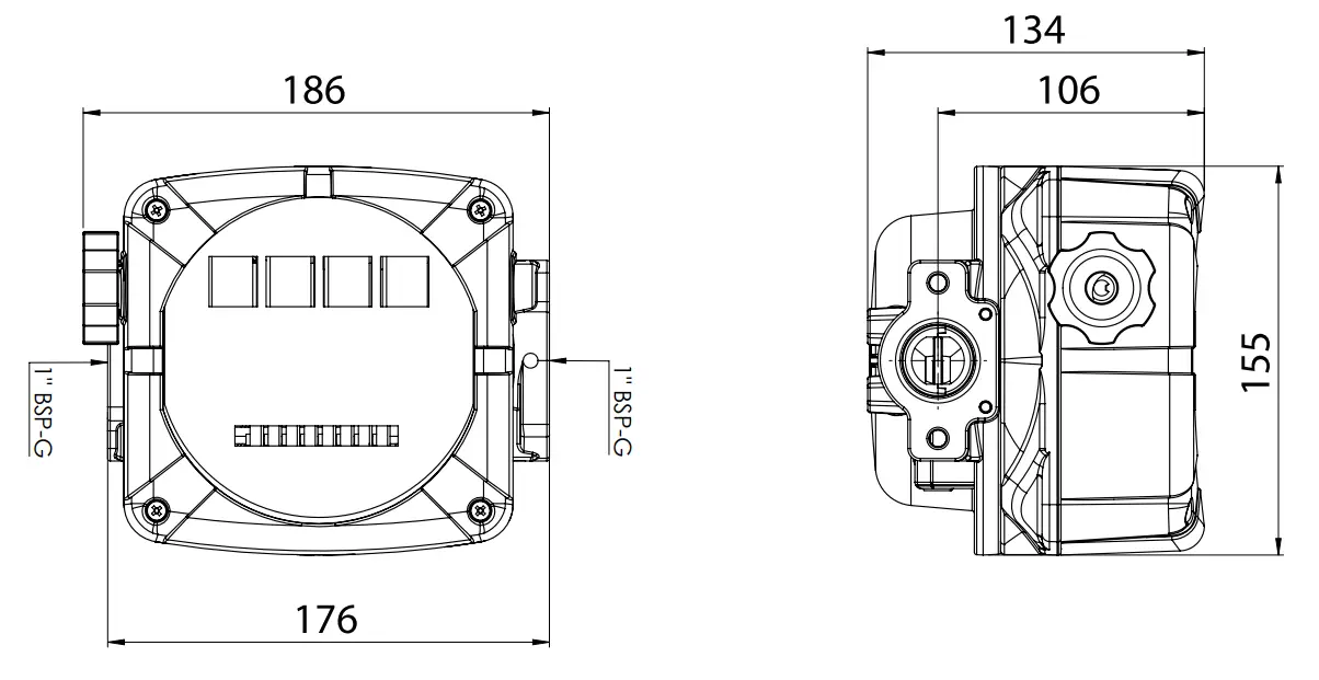
METER DIMENSIONS
TROUBLESHOOTING GUIDE
| Problem | Cause | Solution |
| Meter not reading | 1) Blockage in the fluid chamber | 1) Clear blockage from fluid chamber |
| 2) Meter installed incorrectly | 2) Check the meter orientation (flow must be in direction of the arrow | |
| Batch total does not reset | 1) Reset knob not correctly engaged | 1) Fit reset knob correctly |
| 2) Register is broken | 2) Replace meter | |
| Meter leaking | 1) Damaged o’ring seal | 1) Replace o’ring |
METER SPECIFICATIONS
| Meter Type | Nutating disc |
| Flow rate | 20 – 120 ltr/min |
| Maximum pressure | 3.5bar (50psi) |
| Accuracy | +/- 1% |
| Inlet / Outlet | 1” BSP (F) |
| Temperature | -20 deg C / +50 deg C |
| Display | 4 digit |
| Weight | 1.8 kg |
| Fluid Compatibility | Diesel |
| Materials of construction | NBR, PBT, Brass, Steel |

Note:
This product should be disposed of according to all applicable local and national government environment regulations and guidelines.
For Warranty Terms and Conditions see www.macnaught.com.au
For a list of Australian Service Centres see www.macnaught.com.au
Customer Support
Macnaught Pty Ltd
41-49 Henderson Street
Turrella NSW 2205
Ph: 1800 185 102
Fax: 1800 186 402
E-mail: [email protected]