![]() SVW SERIES
SVW SERIES
Hydronic
2-20 Tons
Owner’s Manual
SVW 2-20 Tons SERIES Vertical Chilled Water
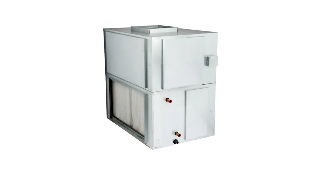
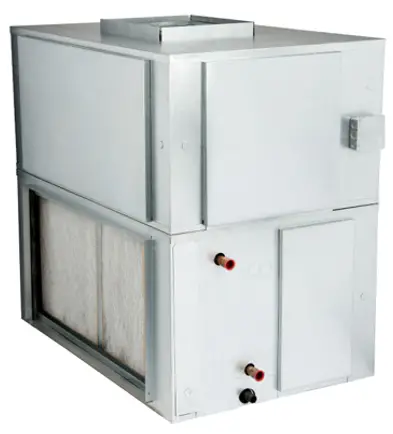
All motors are factory installed Sloped and insulated drain pan Galvanized steel cabinet Insulation meets IAQ standards Manual air vents Belt drive blower Various motor options![]() First Co. commercial – duty SVW chilled or hot water blower coil units are designed for installation within the conditioned area or as remote units with duct systems.
First Co. commercial – duty SVW chilled or hot water blower coil units are designed for installation within the conditioned area or as remote units with duct systems.
SVW SERIES
First Co. commercial – duty SVW chilled or hot water blower coil units are designed for installation within the conditioned area or as remote units with duct systems. Standard 4 row coils can be used for cooling or heating. These air handlers are compact, with large removable panels for installation and ease of service. Separate filter panels are provided on both sides of unit. Optional accessories include 6 row cooling coils, hot water coils, various motor options, mixing boxes, motor starters, and discharge plenums. All models feature positive slope drain pans. Standard models are available in 8 popular sizes 800 through 8000 nominal CFM (2 through 20 tons). All standard models are ETL listed and rated in accordance with ARI Standard 430.
CABINET
Fabricated of heavy gauge galvanized steel. Seismic resistant mounting brackets are standard on 2-5 ton models.
BLOWER
Resiliently mounted, heavy duty, double inlet, forward curved blade, centrifugal type. Each wheel is dynamically balanced for smooth, quiet operation. All blowers are belt driven with field adjustable pulleys to permit variations in static pressure and air requirements. All blowers have ball bearings.
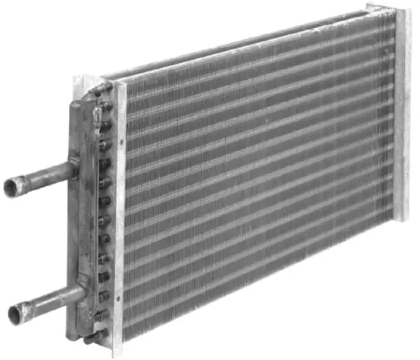
COILS
Fabricated of 3/8” or 1/2” OD seamless copper tubes mechanically expanded to highly efficient aluminum fins to maximize heat transfer. All coils have manual air vents. All models have positive slope drain pans.
INSULATION
The entire interior of the cabinet is insulated with one (1) inch insulation.
FILTER
One inch throw away filters are provided as standard in all 2 – 5 ton units. One inch permanent filters are provided as standard in all 7-1/2 – 20 ton units.
Filters can be changed without tools. Space available for 2”.
FACTORY WIRED
All standard motors are field or factory installed and wired at voltage specified by customer. (If not specified, multi-voltage motors will be wired at highest voltage)
MOTOR
Standard motor is 1725 RPM. The adjustable motor mount permits easy belt adjustment. A variable pitch pulley allows balancing of the system to the desired CFM. Standard motors have internal overload protection. Therefore, units shipped with standard motors will be ETL listed. Most non-standard motors (i.e. 575V, 2-speed, TEFC, some 50 Hz., etc.) are not available with internal overload protection. Therefore, most units shipped with non-standard motors can be ETL listed with the addition of a factory installed motor starter (contact the factory for starter information and ETL verification.)
MISCELLANEOUS – Slotted mounting rails for easy installation. Rails are turned down 1/2” on each end for safer and easier installation.
– 4 x 4 junction box accepts a field installed (24/120V) relay / transformer for low voltage control.
– 3/4 inch NPT drain connections on both sides of cabinet.
– Header connections on the right side as standard.
Knockouts are provided for conversion to the left side. (Looking with air flow).
– Drain pans are coated for corrosion protection.

Options:
Contact the factory
- 6 row cooling coil instead of standard 4 row coil (factory installed only).
- Stainless steel drain pan.
- Motor starters.
- Hot water coil can be field or factory installed in either the reheat or pre-heat position (reheat is standard).
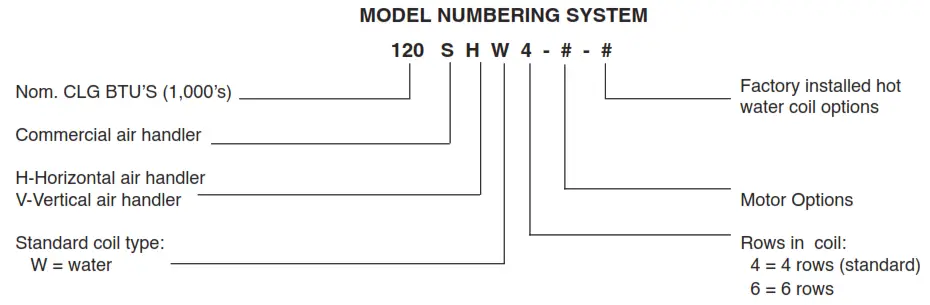
PART NUMBER FOR UNIT MODEL MANIFOLD CONNECTIONS 24HWK 24SHW/SVW 7/8” OD 36HWK 36SHW/SVW 48HWK 48SHW/SVW 60HWK 60SHW/SVW 90HWK 90SHW/SVW 1-1/8” OD 120HWK 120SHW/SVW 1-3/8” OD 180HWK 180SHW/SVW 240HWK 230SHW/SVW 
- Relay / Transformer mounts directly on 4 x 4 junstion box on each unit.
Part number is 310-E301 (24/120V), 310-E302 (24.208-230V) and 310-E303 (24/277V) – (for 2-5 ton models only)
Options (Cont.):
Mixing Boxes
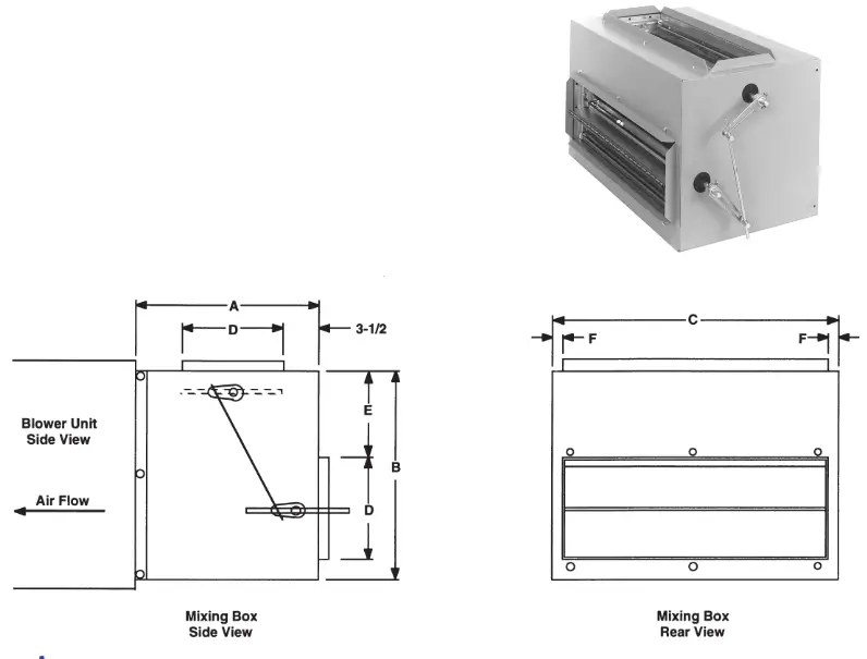
Dimensions:
| MODEL | FOR UNIT MODEL | A | B | C | D | E | F | DAMPER SIZE (NOM) | SHIPPING WEIGHT |
| 24MB | 24SH, SV | 16 | 16-3/8 | 18-1/8 | 8 | 6 | 1-1/16 | 2-16 x 8 | 40 |
| 36MB | 36SH, SV | 16 | 16-3/8 | 27-5/8 | 8 | 6 | 1-1/16 | 2-26 x 8 | 58 |
| 48MB | 48SH, SV | 18 | 20-3/8 | 29-1/8 | 10 | 8 | 1-1/16 | 2-27 x 10 | 65 |
| 60MB | 60SH, SV | 18 | 20-3/8 | 36-1/8 | 10 | 8 | 1-1/16 | 2-34 x 10 | 78 |
| 90MB | 90SH, SV | 18 | 25-3/8 | 45-1/8 | 10 | 8 | 1-1/16 | 2-42 x 10 | 110 |
| 120MB | 120SH, SV | 20 | 30-3/8 | 48-1/8 | 12 | 10 | 1-1/16 | 2-46 x 12 | 135 |
| 180MB | 180SH, SV | 22 | 37-7/8 | 57-1/8 | 14 | 12 | 1-9/16 | 2-54 x 14 | 190 |
| 240MB | 240SH, SV | 22 | 50-1/2 | 57-1/8 | 14 | 24 | 1-9/16 | 2-54 x 14 | 210 |
Features:
- Cabinet fully insulated – 3/4 inch.
- Embossed galvanized cabinet on 24-230MB.
- Crank arms and linkage rod for damper connection are furnished. Connections can be made on either side of mixing boxes. The balance of necessary linkage hardware, damper motor, and controls to be field supplied.
- Dampers can be positioned for either rear/top or rear/bottom locations.
- 1” duct flanges provided on damper openings.
- Dampers have air seals on the edges for positive closing. 24-90MB have single horizontal damper blades. 120-230MB have double horizontal damper blades.
- When used with water coil units, a “freezestat” must be installed to prevent coil damage caused by low ambient conditions.
SVW SERIES
COMPONENT STATIC RESISTANCE
| MODEL | NOMINAL CFM | COMPONENT STATIC RESISTANCE (INCHES OF WATER) | ||||
| CABINET | COOLING COIL* | HEATING COIL | FILTER | |||
| 4 ROW | 6 ROW | 2 ROW | ||||
| 24SVW | 600 | 0.09 | 0.14 | 0.22 | 0.07 | 0.04 |
| 700 | 0.10 | 0.18 | 0.27 | 0.09 | 0.05 | |
| 800 | 0.11 | 0.23 | 0.34 | 0.12 | 0.06 | |
| 900 | 0.12 | 0.28 | 0.42 | 0.14 | 0.07 | |
| 1000 | 0.13 | 0.33 | 0.50 | 0.18 | 0.08 | |
| 36SVW | 1000 | 0.09 | 0.17 | 0.25 | 0.08 | 0.04 |
| 1100 | 0.10 | 0.19 | 0.28 | 0.10 | 0.05 | |
| 1200 | 0.11 | 0.23 | 0.34 | 0.12 | 0.06 | |
| 1300 | 0.12 | 0.26 | 0.39 | 0.13 | 0.07 | |
| 1400 | 0.13 | 0.30 | 0.45 | 0.15 | 0.08 | |
| 48SVW | 1400 | 0.09 | 0.18 | 0.27 | 0.09 | 0.05 |
| 1500 | 0.10 | 0.20 | 0.31 | 0.10 | 0.06 | |
| 1600 | 0.11 | 0.23 | 0.34 | 0.11 | 0.06 | |
| 1700 | 0.12 | 0.25 | 0.38 | 0.12 | 0.07 | |
| 1800 | 0.13 | 0.28 | 0.42 | 0.13 | 0.08 | |
| 60SVW | 1800 | 0.10 | 0.20 | 0.28 | 0.09 | 0.05 |
| 1900 | 0.11 | 0.21 | 0.31 | 0.10 | 0.06 | |
| 2000 | 0.12 | 0.23 | 0.34 | 0.11 | 0.06 | |
| 2100 | 0.13 | 0.25 | 0.37 | 0.12 | 0.07 | |
| 2200 | 0.15 | 0.28 | 0.40 | 0.13 | 0.08 | |
| MODEL | NOMINAL CFM | COMPONENT STATIC RESISTANCE (INCHES OF WATER) | ||||
| CABINET | COOLING COIL* | HEATING COIL | FILTER | |||
| 4 ROW | 6 ROW | 2 ROW | ||||
| 90SVW | 2500 | 0.12 | 0.26 | 0.39 | 0.13 | 0.04 |
| 2750 | 0.14 | 0.30 | 0.45 | 0.16 | 0.05 | |
| 3000 | 0.16 | 0.34 | 0.51 | 0.18 | 0.06 | |
| 3250 | 0.17 | 0.39 | 0.58 | 0.21 | 0.07 | |
| 3500 | 0.19 | 0.44 | 0.65 | 0.24 | 0.08 | |
| 120SVW | 3400 | 0.14 | 0.29 | 0.43 | 0.14 | 0.05 |
| 3700 | 0.15 | 0.33 | 0.48 | 0.16 | 0.06 | |
| 4000 | 0.17 | 0.37 | 0.54 | 0.19 | 0.07 | |
| 4300 | 0.19 | 0.41 | 0.61 | 0.21 | 0.08 | |
| 4600 | 0.21 | 0.45 | 0.67 | 0.24 | 0.09 | |
| 180SVW | 5200 | 0.16 | 0.30 | 0.44 | 0.14 | 0.05 |
| 5600 | 0.17 | 033 | 0.49 | 0.16 | 0.06 | |
| 6000 | 0.19 | 0.37 | 0.55 | 0.18 | 0.07 | |
| 6400 | 0.21 | 0.41 | 0.61 | 0.20 | 0.08 | |
| 6800 | 0.23 | 0.45 | 0.66 | 0.23 | 0.09 | |
| 240SVW | 6000 | 0.11 | 0.21 | 0.31 | 0.10 | 0.04 |
| 7000 | 0.16 | 0.30 | 0.44 | 0.14 | 0.05 | |
| 8000 | 0.19 | 0.37 | 0.55 | 0.18 | 0.07 | |
| 9000 | 0.23 | 0.45 | 0.66 | 0.23 | 0.09 | |
| 10000 | 0.29 | 0.58 | 0.86 | 0.28 | 0.11 | |
* Wet Coil (Dry Coil P.D. = Wet P.D. x .70)
UNIT SELECTION PROCEDURE
- Complete as much of the “INFORMATION REQUIRED FOR UNIT SELECTION” on page 2 as possible.
Example:
INFORMATION REQUIRED FOR UNIT SELECTION
System Type ( circle one) : 2 – pipe (1 coil ) or 4 – pipe ( sep. htg. & clg. coils )
CFM ___3900___
E.S.P. __.80___ MOTOR: HP:_________VOLTAGE:____230____PHASE:___3___
COOLING: INDOOR: DB _________ WB _____________OUTDOOR:
DB___________
TOTAL BTUH____158,000___SENS. BTUH ____________ GPM __________EWT ___45____
HEATING:
TOTAL BTUH ___________GPM___________EWT___________EAT___________
MISC: ___________ - Select the unit model that meets the required total MBH cooling and heating at the required conditions from tables on pages 16 – 23 (capacities and air are the same for SHW and SVW models).
Example: Required clg. capacity = 158,000 BTUH clg. @ 45 degree EWT Unit selected = 120SHW6 - Refer to page 7 for the balance of the selection procedure: If the required CFM falls within the range for the selected model, proceed to number 4. If not, use the First Co. Computer Selection Program or contact the factory for assistance.
- Determine the required motor horsepower by matching the selected model (i.e. 120SHW6) with the closest CFM at the required External Static Pressure (ESP). Note the horsepower (HP) at the top of the CFM range that is needed.
Example: Required CFM is 3900 at .80 ESP.
HP required = 2 HP - Select the motor voltage, phase, and horsepower and then the appropriate Motor Drive Assembly Number that applies.
Example: Above example requires Motor Drive Assembly Number 984120-G3
| Model CFM | Available External Static Range | Total Static In. | ||||
| 2 Row | 4 Row | 4R/2R | 6 Row | 6R/2R | ||
| Coil | Coil | Coil | Coil | Coil | ||
| 24S(*)W | 24S(*)W2 | 24S(*)W4 | 24S(*)W42 | 24S(*)W6 | 24S(*)W62 | |
| – 1/4 HP – | ||||||
| 700 | 0.13 – 0.80 | 0.04 – 0.71 | 0.00 – 0.62 | 0.00 – 0.61 | 0.00 – 0.53 | 0.37 – 1.04 |
| 800 | 0.00 – 0.63 | 0.00 – 0.52 | 0.00 – 0.41 | 0.00 – 0.41 | 0.00 – 0.29 | 0.33 – 0.92 |
| 900 | 0.00 – 0.44 | 0.00 – 0.30 | 0.00 – 0.16 | 0.00 – 0.16 | 0.00 – 0.02 | 0.28 – 0.77 |
| – 1/3 HP – | ||||||
| 700 | 0.36 – 1.23 | 0.27 – 1.14 | 0.18 – 1.05 | 0.17 – 1.04 | 0.09 – 0.96 | 0.60 – 1.47 |
| 800 | 0.29 – 1.03 | 0.18 – 0.92 | 0.07 – 0.81 | 0.07 – 0.81 | 0.00 – 0.69 | 0.58 – 1.32 |
| 900 | 0.21 – 0.83 | 0.07 – 0.69 | 0.00 – 0.55 | 0.00 – 0.55 | 0.00 – 0.41 | 0.54 – 1.16 |
| – 1/2 HP – | ||||||
| 700 | 0.64 -1.62 | 0.55 – 1.53 | 0.46 – 1.44 | 0.45 – 1.43 | 0.37 – 1.35 | 0.88 – 1.86 |
| 800 | 0.59 -1.62 | 0.48 – 1.51 | 0.37 – 1.40 | 0.37 – 1.40 | 0.25 – 1.28 | 0.88 – 1.91 |
| 900 | 0.54 -1.52 | 0.40 – 1.38 | 0.26 – 1.24 | 0.26 – 1.24 | 0.12 – 1.10 | 0.87 – 1.85 |
| – 3/4 HP – | ||||||
| 700 | 0.90 – 1.62 | 0.81 – 1.53 | 0.72 – 1.44 | 0.71 – 1.43 | 0.63 – 1.35 | 1.14 – 1.86 |
| 800 | 0.87 – 1.62 | 0.76 – 1.51 | 0.65 – 1.40 | 0.65 – 1.40 | 0.53 – 1.28 | 1.16 – 1.91 |
| 900 | 0.84 – 1.61 | 0.70 – 1.47 | 0.56 – 1.33 | 0.56 – 1.33 | 0.42 – 1.19 | 1.17 – 1.94 |
| 36S(*)W | 36S(*)W2 | 36S(*)W4 | 36S(*)W42 | 36S(*)W6 | 36S(*)W62 | |
| – 1/3 HP – | ||||||
| 1000 | 0.13 – 0.74 | 0.00 – 0.65 | 0.00 – 0.57 | 0.00 – 0.57 | 0.00 – 0.49 | 0.34 – 0.95 |
| 1100 | 0.07 – 0.61 | 0.00 – 0.52 | 0.00 – 0.42 | 0.00 – 0.43 | 0.00 – 0.33 | 0.32 – 0.86 |
| 1200 | 0.00 – 0.47 | 0.00 – 0.36 | 0.00 – 0.24 | 0.00 – 0.25 | 0.00 – 0.13 | 0.29 – 0.76 |
| 1300 | 0.00 – 0.34 | 0.00 – 0.21 | 0.00 – 0.08 | 0.00 – 0.08 | 0.00 – 0.00 | 0.26 – 0.66 |
| – 1/2 HP – | ||||||
| 1000 | 0.34 – 1.34 | 0.25 – 1.25 | 0.17 – 1.17 | 0.17 – 1.17 | 0.09 – 1.09 | 0.55 – 1.55 |
| 1100 | 0.29 – 1.19 | 0.20 – 1.10 | 0.10 – 1.00 | 0.11 – 1.01 | 0.00 – 0.91 | 0.54 – 1.44 |
| 1200 | 0.24 – 1.04 | 0.13 – 0.93 | 0.00 – 0.81 | 0.00 – 0.82 | 0.00 – 0.70 | 0.53 – 1.33 |
| 1300 | 0.18 – 0.90 | 0.05 – 0.77 | 0.00 – 0.64 | 0.00 – 0.64 | 0.00 – 0.51 | 0.50 – 1.22 |
| – 3/4 HP – | ||||||
| 1000 | 0.88 – 1.55 | 0.79 – 1.46 | 0.71 – 1.38 | 0.71 – 1.38 | 0.63 – 1.30 | 1.09 – 1.76 |
| 1100 | 0.86 – 1.55 | 0.77 – 1.46 | 0.67 – 1.36 | 0.68 – 1.37 | 0.58 – 1.27 | 1.11 – 1.80 |
| 1200 | 0.82 – 1.54 | 0.71 – 1.43 | 0.59 – 1.31 | 0.60 – 1.32 | 0.48 – 1.20 | 1.11 – 1.83 |
| 1300 | 0.78 – 1.51 | 0.65 – 1.38 | 0.52 – 1.25 | 0.52 – 1.25 | 0.39 – 1.12 | 1.10 – 1.83 |
| 48S(*)W | 48S(*)W2 | 48S(*)W4 | 48S(*)W42 | 48S(*)W6 | 48S(*)W62 | |
| – 1/2 HP – | ||||||
| 1500 | 0.17 – 0.75 | 0.07 – 0.65 | 0.00 – 0.55 | 0.00 – 0.54 | 0.00 – 0.44 | 0.43 – 1.01 |
| 1600 | 0.12 – 0.66 | 0.00 – 0.54 | 0.00 – 0.43 | 0.00 – 0.43 | 0.00 – 0.32 | 0.40 – 0.94 |
| 1700 | 0.06 – 0.55 | 0.00 – 0.42 | 0.00 – 0.30 | 0.00 – 0.29 | 0.00 – 0.17 | 0.37 – 0.86 |
| – 3/4 HP – | ||||||
| 1500 | 0.46 – 1.37 | 0.36 – 1.27 | 0.26 – 1.17 | 0.25 – 1.16 | 0.15 – 1.06 | 0.72 – 1.63 |
| 1600 | 0.42 – 1.26 | 0.30 – 1.14 | 0.19 – 1.03 | 0.19 – 1.03 | 0.08 – 0.92 | 0.70 – 1.54 |
| 1700 | 0.37 – 1.15 | 0.24 – 1.02 | 0.12 – 0.90 | 0.11 – 0.89 | 0.00 – 0.77 | 0.68 – 1.46 |
| – 1 HP – | ||||||
| 1500 | 0.88 – 1.63 | 0.78 – 1.53 | 0.68 – 1.43 | 0.67 – 1.42 | 0.57 – 1.32 | 1.14 – 1.89 |
| 1600 | 0.85 – 1.63 | 0.73 – 1.51 | 0.62 – 1.40 | 0.62 – 1.40 | 0.51 – 1.29 | 1.13 – 1.91 |
| 1700 | 0.81 – 1.61 | 0.68 – 1.48 | 0.56 – 1.36 | 0.55 – 1.35 | 0.43 – 1.23 | 1.12 – 1.92 |
| 60S(*)W | 60S(*)W2 | 60S(*)W4 | 60S(*)W42 | 60S(*)W6 | 60S(*)W62 | |
| – 1/2 HP – | ||||||
| 1900 | 0.15 – 0.59 | 0.00 – 0.48 | 0.00 – 0.38 | 0.00 – 0.38 | 0.00 – 0.28 | 0.42 – 0.86 |
| 2000 | 0.11 – 0.51 | 0.00 – 0.39 | 0.00 – 0.28 | 0.00 – 0.28 | 0.00 – 0.17 | 0.40 – 0.80 |
| 12100 | 0.06 – 0.42 | 0.00 – 0.29 | 0.00 – 0.17 | 0.00 – 0.17 | 0.00 – 0.05 | 0.38 – 0.74 |
| – 3/4 HP – | ||||||
| 1900 | 0.44 – 1.16 | 0.33 – 1.05 | 0.23 – 0.95 | 0.23 – 0.95 | 0.13 – 0.85 | 0.71 – 1.43 |
| 2000 | 0.42 – 1.08 | 0.30 – 0.96 | 0.19 – 0.85 | 0.19 – 0.85 | 0.08 – 0.74 | 0.71 – 1.37 |
| 2100 | 0.38 – 0.99 | 0.25 – 0.86 | 0.13 – 0.74 | 0.13 – 0.74 | 0.00 – 0.62 | 0.70 – 1.31 |
| – 1 HP – | ||||||
| 1900 | 0.77 – 1.57 | 0.66 – 1.46 | 0.56 – 1.36 | 0.56 – 1.36 | 0.46 – 1.26 | 1.04 – 1.84 |
| 2000 | 0.76 – 1.51 | 0.64 – 1.39 | 0.53 – 1.28 | 0.53 – 1.28 | 0.42 – 1.17 | 1.05 – 1.80 |
| 2100 | 0.74 – 1.43 | 0.61 – 1.30 | 0.49 – 1.18 | 0.49 – 1.18 | 0.37 – 1.06 | 1.06 – 1.75 |
| – 1-1/2 HP – | ||||||
| 1900 | 1.10 – 1.91 | 0.99 – 1.80 | 0.89 – 1.70 | 0.89 – 1.70 | 0.79 – 1.60 | 1.37 – 2.18 |
| 2000 | 1.09 – 1.91 | 0.97 – 1.79 | 0.86 – 1.68 | 0.86 – 1.68 | 0.75 – 1.57 | 1.38 – 2.20 |
| 2100 | 1.07 – 1.90 | 0.94 – 1.77 | 0.82 – 1.65 | 0.82 – 1.65 | 0.70 – 1.53 | 1.39 – 2.22 |
| *H = Horizontal, V = Vertical | ||||||
| Model CFM | Available External Static Range | Total Static In. | ||||
| 2 Row | 4 Row | 4R/2R | 6 Row | 6R/2R | ||
| Coil | Coil | Coil | Coil | Coil | ||
| 90S(*)W | 90S(*)W2 | 90S(*)W4 | 90S(*)W42 | 90S(*)W6 | 90S(*)W62 | |
| – 3/4 HP – | ||||||
| 2800 | 0.00 – 0.73 | 0.00 – 0.58 | 0.00 – 0.42 | 0.00 – 0.43 | 0.00 – 0.27 | 0.34 – 1.09 |
| 3000 | 0.00 – 0.51 | 0.00 – 0.35 | 0.00 – 0.17 | 0.00 – 0.18 | 0.00 – 0.00 | 0.33 – 0.91 |
| 3200 | 0.00 – 0.30 | 0.00 – 0.13 | 0.00 – 0.00 | 0.00 – 0.00 | 0.00 – 0.00 | 0.31 – 0.74 |
| – 1 HP – | ||||||
| 2800 | 0.38 – 1.17 | 0.23 – 1.02 | 0.07 – 0.86 | 0.08 – 0.87 | 0.00 – 0.71 | 0.74 – 1.53 |
| 3000 | 0.33 – 0.92 | 0.17 – 0.76 | 0.00 – 0.58 | 0.00 – 0.59 | 0.00 – 0.41 | 0.73 – 1.32 |
| 3200 | 0.27 – 0.70 | 0.10 – 0.53 | 0.00 – 0.32 | 0.00 – 0.34 | 0.00 – 0.14 | 0.71 – 1.14 |
| – 1-1/2 HP – | ||||||
| 2800 | 0.63 -1.80 | 0.48 – 1.65 | 0.32 – 1.49 | 0.33 – 1.50 | 0.17 – 1.34 | 0.99 – 2.16 |
| 3000 | 0.59 -1.74 | 0.43 – 1.58 | 0.25 – 1.40 | 0.26 – 1.41 | 0.08 – 1.23 | 0.99 – 2.14 |
| 3200 | ||||||
| – 2 HP – | ||||||
| 2800 | 1.01 – 1.80 | 0.86 – 1.65 | 0.70 – 1.49 | 0.71 – 1.50 | 0.55 – 1.34 | 1.37 – 2.16 |
| 3000 | 0.97 – 0.75 | 0.81 – 1.63 | 0.63 – 1.45 | 0.64 – 1.46 | 0.46 – 1.28 | 1.37 – 2.19 |
| 3200 | 0.93 – 1.77 | 0.76 – 1.60 | 0.55 – 1.39 | 0.57 – 1.41 | 0.37 – 1.21 | 1.37 – 2.21 |
| 120S(*)W | 120S(*)W2 | 120S(*)W4 | 120S(*)W42 | 120S(*)W6 | 120S(*)W62 | |
| – 1-1/2 HP – | ||||||
| 3800 | 0.02 – 0.97 | 0.00 – 0.80 | 0.00 – 0.63 | 0.00 – 0.64 | 0.00 – 0.47 | 0.41 – 1.36 |
| 4000 | 0.00 – 0.75 | 0.00 – 0.57 | 0.00 – 0.38 | 0.00 – 0.40 | 0.00 – 0.21 | 0.37 – 1.18 |
| 4200 | 0.00 – 0.55 | 0.00 – 0.35 | 0.00 – 0.15 | 0.00 – 0.17 | 0.00 – 0.00 | 0.33 – 1.01 |
| – 2 HP – | ||||||
| 3800 | 0.51 – 1.65 | 0.34 – 1.48 | 0.17 – 1.31 | 0.18 – 1.32 | 0.01 – 1.15 | 0.90 – 2.04 |
| 4000 | 0.43 – 1.42 | 0.25 – 1.24 | 0.06 – 1.05 | 0.08 – 1.07 | 0.00 – 0.88 | 0.86 – 1.85 |
| 4200 | 0.36 – 1.20 | 0.16 – 1.00 | 0.00 – 0.80 | 0.00 – 0.82 | 0.00 – 0.61 | 0.82 – 1.66 |
| – 3 HP – | ||||||
| 3800 | ||||||
| 4000 | 0.92 – 1.52 | 0.74 – 1.34 | 0.55 – 1.15 | 0.57 – 1.17 | 0.38 – 0.98 | 1.35 – 1.95 |
| 4200 | 0.85 – 1.47 | 0.65 – 1.27 | 0.45 – 1.07 | 0.47 – 1.09 | 0.28 – 0.88 | 1.31 – 1.93 |
| 180S(*)W | 180S(*)W2 | 180S(*)W4 | 180S(*)W42 | 180S(*)W6 | 180S(*)W62 | |
| – 2 HP – | ||||||
| 5800 | 0.24 – 0.92 | 0.06 – 0.74 | 0.00 – 0.57 | 0.00 – 0.57 | 0.00 – 0.40 | 0.66 – 1.34 |
| 6000 | 0.20 – 0.77 | 0.00 – 0.58 | 0.00 – 0.40 | 0.00 – 0.40 | 0.00 – 0.22 | 0.64 – 1.21 |
| 6200 | 0.16 – 0.63 | 0.00 – 0.43 | 0.00 – 0.24 | 0.00 – 0.24 | 0.00 – 0.05 | 0.62 – 1.09 |
| – 3 HP – | ||||||
| 5800 | 0.50 – 1.62 | 0.32 – 1.44 | 0.15 – 1.27 | 0.15 – 1.27 | 0.00 – 1.10 | 0.92 – 2.04 |
| 6000 | 0.46 – 1.60 | 0.27 – 1.41 | 0.09 – 1.23 | 0.09 – 1.23 | 0.00 – 1.05 | 0.90 – 2.04 |
| 6200 | 0.42 – 1.47 | 0.22 – 1.27 | 0.03 – 1.08 | 0.00 – 1.08 | 0.00 – 0.89 | 0.88 – 1.93 |
| 240S(*)W | 230S(*)W2 | 230S(*)W4 | 230S(*)W42 | 230S(*)W6 | 230S(*)W62 | |
| – 3 HP – | ||||||
| 7500 | 0.08 – 0.79 | 0.00 – 0.61 | 0.00 – 0.45 | 0.00 – 0.45 | 0.00 – 0.31 | 0.47 – 1.18 |
| 8000 | 0.00 – 0.45 | 0.00 – 0.26 | 0.00 – 0.08 | 0.00 – 0.08 | 0.00 – 0.00 | 0.39 – 0.89 |
| 8500 | 0.00 – 0.13 | 0.00 – 0.00 | 0.00 – 0.00 | 0.00 – 0.00 | 0.00 – 0.00 | 0.29 – 0.62 |
| – 5 HP – | ||||||
| 7500 | 0.20 – 1.79 | 0.00 – 1.61 | 0.00 – 1.45 | 0.00 – 1.45 | 0.00 – 1.31 | 0.59 – 2.18 |
| 8000 | 0.07 – 1.71 | 0.00 – 1.52 | 0.00 – 1.34 | 0.00 – 1.34 | 0.00 – 1.17 | 0.51 – 2.15 |
| 8500 | 0.00 – 1.39 | 0.00 – 1.18 | 0.00 – 0.98 | 0.00 – 0.99 | 0.00 – 0.79 | 0.42 – 1.88 |
| *H = Horizontal, V = Vertical | ||||||
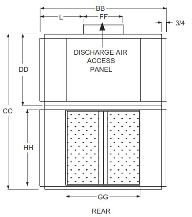
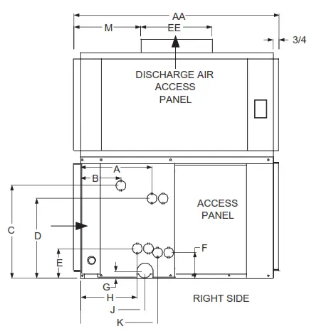
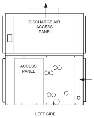
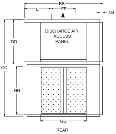
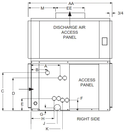
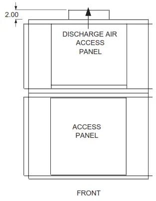
Physical Data – Models 24SVW – 60SVW
UNIT DIMENSIONS
| MODEL | UNIT CABINET | BLOWER OUTLET | RETURN DUCT CONNECTION | |||||
| AA | BB | CC | DD | EE | FF | GG | HH | |
| 24SVW4 | 31-3/4 | 28-1/2 | 35-1/8 | 16-1/4 | 11 | 9 | 18 | 16-1/4 |
| 36SVW4 | 31-3/4 | 38 | 35-1/8 | 16-1/4 | 10-7/8 | 12-5/8 | 27-1/2 | 16-1/4 |
| 48SVW4 | 31-3/4 | 39-1/2 | 41-7/8 | 19 | 11-3/4 | 13-5/8 | 29 | 20-1/4 |
| 60SVW4 | 31-1/4 | 46-1/2 | 43-1/8 | 20-1/4 | 13-7/8 | 16 | 36 | 20-1/4 |
| 24SVW6 | 31-3/4 | 28-1/2 | 35-1/8 | 16-1/4 | 11 | 9 | 18 | 16-1/4 |
| 36SVW6 | 31-3/4 | 38 | 35-1/8 | 16-1/4 | 10-7/8 | 12-5/8 | 27-1/2 | 16-1/4 |
| 48SVW6 | 31-3/4 | 39-1/2 | 41-7/8 | 19 | 11-3/4 | 13-5/8 | 29 | 20-1/4 |
| 60SVW6 | 31-1/4 | 46-1/2 | 43-1/8 | 20-1/4 | 13-7/8 | 16 | 36 | 20-1/4 |
| STUBOUT LOCATION FOR WATER COILS | |||||||||||
| A | B | C | D | E | F | G | H | J | K | L | M |
| 11-1/4 | 6-5/16 | 14-5/16 | 12-5/16 | 4-1/2 | 3-15/16 | 1 | 8-15/16 | 10 | 12 | 9-3/4 | 6-3/4 |
| 11-1/4 | 6-5/16 | 14-5/16 | 12-5/16 | 4-1/2 | 3-15/16 | 1 | 8-15/16 | 10 | 12 | 12-3/4 | 6-3/4 |
| 11-1/4 | 6-5/16 | 19 | 17 | 4-1/2 | 3-15/16 | 1 | 8-15/16 | 10 | 12 | 13 | 7 |
| 11-1/4 | 6-5/16 | 19 | 17 | 4-1/2 | 3-15/16 | 1 | 8-15/16 | 10 | 12 | 15-1/8 | 7-5/8 |
| 12-15/16 | 6-5/16 | 14-5/16 | 12-5/16 | 4-1/2 | 3-15/16 | 1 | 10-5/8 | 10 | 13-3/4 | 9-3/4 | 6-3/4 |
| 12-15/16 | 6-5/16 | 14-5/16 | 12-5/16 | 4-1/2 | 3-15/16 | 1 | 10-5/8 | 10 | 13-3/4 | 12-3/4 | 6-3/4 |
| 12-15/16 | 6-5/16 | 19 | 17 | 4-1/2 | 3-15/16 | 1 | 10-5/8 | 10 | 13-3/4 | 13 | 7 |
| 12-15/16 | 6-5/16 | 19 | 17 | 4-1/2 | 3-15/16 | 1 | 10-5/8 | 10 | 13-3/4 | 15-1/8 | 7-5/8 |
Notes:
- All drain connections are 3/4” MPT and located on same side as coil connections.
- All units have knockouts on both sides for either (standard) or left side coil stub outs.
(Looking with airflow) All coil connections must be on the same side of the unit.
GENERAL SPECIFICATIONS
| MODEL | NOM. COOL TONS | FACE AREA SQ. FT. | TUBE SIZE | STD. MOTOR HP | VOLTS | PHASE |
| 24SVW | 2 | 2.05 | 3/8 | 1/4 | 115 | 1 |
| 36SVW | 3 | 3.05 | 3/8 | 1/3 | 115 | 1 |
| 48SVW | 4 | 4.0 | 3/8 | 1/2 | 115 | 1 |
| 60SVW | 5 | 5.0 | 3/8 | 1/2 | 115 | 1 |
| BLOWER SIZE | FILTER SIZE | 4 ROW COIL | 6 ROW COIL | ||
| MANIFOLD CONNECTION | SHIPPING WEIGHT | MANIFOLD CONNECTION | SHIPPING WEIGHT | ||
| 9 X 6 | 16 X 25 | 7/8” O/D (SWT) | 185 | 7/8” O/D (SWT) | 205 |
| 9 X 9 | 16 X 16 (2) | 7/8” O/D (SWT) | 225 | 7/8” O/D (SWT) | 245 |
| 10 X 10 | 16 X 20 (2) | 7/8” O/D (SWT) | 265 | 7/8” O/D (SWT) | 290 |
| 12 X 12 | 20 X 20 (2) | 1-1/8” O/D (SWT) | 345 | 1-1/8” O/D (SWT) | 365 |
Notes:
- All technical specifications subject to change without notice.
- Additional charge for optional motors.
- When SVW units are used with hot water coil the leaving air temperature must not exceed 150 degrees. At high altitude conditions, blower motor may cutout air lower LAT. Contact factory for information.
- Contact factory for electric heat information (supplied by others)
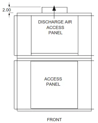
Physical Data – Models 90SVW – 240SVW
UNIT DIMENSIONS
| MODEL | UNIT CABINET | BLOWER OUTLET | RETURN DUCT CONNECTION | |||||
| AA | BB | CC | DD | EE | FF | GG | HH | |
| 90SVW4 | 37-1/2 | 55-1/2 | 51 | 24 | 16-3/8 | 19-1/8 | 45 | 25-1/4 |
| 120SVW4 | 37-1/2 | 58-1/2 | 56 | 24 | 16-3/8 | 19-1/8 | 48 | 30-1/4 |
| 180SVW4 | 46-1/4 | 66 | 63-1/8 | 23-5/8 | 16-1/2 | 45 | 57 | 37-3/4 |
| 240SVW4 | 46-1/4 | 66 | 75-1/2 | 23-5/8 | 16-1/2 | 45 | 57 | 50-1/4 |
| 90SVW6 | 37-1/2 | 55-1/2 | 51 | 24 | 16-3/8 | 19-1/8 | 45 | 25-1/4 |
| 120SVW6 | 37-1/2 | 58-1/2 | 56 | 24 | 16-3/8 | 19-1/8 | 48 | 30-1/4 |
| 180SVW6 | 46-1/4 | 66 | 63-1/8 | 23-5/8 | 16-1/2 | 45 | 57 | 37-3/4 |
| 240SVW6 | 46-1/4 | 66 | 75-1/2 | 23-5/8 | 16-1/2 | 45 | 57 | 50-1/4 |
| STUBOUT LOCATION FOR WATER COILS | |||||||||
| C | D | E | F | G | H | J | K | L | M |
| 24-1/2 | 21-3/4 | 6-3/8 | 6-3/8 | 1 | 9-3/4 | 10-5/8 | 12-1/2 | 18-1/4 | 11-1/4 |
| 29-1/2 | 36-3/4 | 6-3/8 | 6-3/8 | 1 | 9-3/4 | 10-5/8 | 12-1/2 | 19-3/4 | 9-3/4 |
| 37 | 34-1/4 | 6-3/8 | 6-3/8 | 1 | 9-3/4 | 10-5/8 | 12-1/2 | 11-1/4 | 9 |
| 49-1/2 | 46-3/4 | 6-3/8 | 6-3/8 | 1 | 9-3/4 | 10-5/8 | 12-1/2 | 11-1/4 | 9 |
| 24-1/2 | 21-3/4 | 6-3/8 | 6-3/8 | 1 | 11-7/8 | 10-5/8 | 14-11/16 | 18-1/4 | 11-1/4 |
| 29-1/2 | 36-3/4 | 6-3/8 | 6-3/8 | 1 | 11-7/8 | 10-5/8 | 14-11/16 | 19-3/4 | 9-3/4 |
| 37 | 34-1/4 | 6-3/8 | 6-3/8 | 1 | 11-7/8 | 10-5/8 | 14-11/16 | 11-1/4 | 9 |
| 49-1/2 | 46-3/4 | 6-3/8 | 6-3/8 | 1 | 11-7/8 | 10-5/8 | 14-11/16 | 11-1/4 | 9 |
Notes:
- All drain connections are 3/4” MPT and located on same side as coil connections.
- All units have knockouts on both sides for either (standard) or left side coil stub outs
(Looking with airflow). All coil connections must be on the same side of the unit.
GENERAL SPECIFICATIONS
| MODEL | NOM. COOL TONS | FACE AREA SQ. FT. | TUBE SIZE | STD. MOTOR HP | VOLTS | PHASE |
| 90SVW | 7-1/2 | 7.5 | 1/2 | 3/4 | 115/230 | 1 |
| 120SVW | 10 | 9.6 | 1/2 | 1-1/2 | 230/460 | 3 |
| 180SVW | 15 | 14.3 | 1/2 | 1-1/2 | 230/460 | 3 |
| 240SVW | 20 | 19.1 | 1/2 | 3 | 230/460 | 3 |
| BLOWER SIZE | FILTER SIZE | 4 ROW COIL | 6 ROW COIL | ||
| MANIFOLD CONNECTION | SHIPPING WEIGHT | MANIFOLD CONNECTION | SHIPPING WEIGHT | ||
| 15 X 15 | 24 X 25 (2) | 1-1/8” O/D (SWT) | 460 | 1-1/8” O/D (SWT) | 485 |
| 15 X 15 | 26 X 29 (2) | 1-3/8” O/D (SWT) | 575 | 1-3/8” O/D (SWT) | 620 |
| 15 X 12 (2) | 20 X 36.5 (3) | 1-3/8” O/D (SWT) | 805 | 1-3/8” O/D (SWT) | 795 |
| 15 X 12 (2 | 20 X 49 (3) | 1-3/8” O/D (SWT) | 925 | 1-3/8” O/D (SWT) | 965 |
Notes:
- All technical specifications subject to change without notice.
- Additional charge for optional motors.
- When SVW units are used with hot water coil the leaving air temperature must not exceed 150 degrees. At high altitude conditions, blower motor may cutout air lower LAT. Contact factory for information.
- Contact factory for electric heat information (supplied by others).
2 – 5 TON FAN PERFORMANCE
| MODEL | NOMINAL CFM | COIL FACE VELOCITY FPM | TOTAL STATIC PRESSURE – INCHES OF WATER | |||||||||
| 0.5 | 0.6 | 0.7 | 0.8 | 0.9 | ||||||||
| RPM | HP | RPM | HP | RPM | HP | RPM | HP | RPM | HP | |||
| 24SVW | 600 | 300 | 770 | 1/6 | 840 | 1/6 | 900 | 1/6 | 990 | 1/4 | 1050 | 1/4 |
| 700 | 350 | 780 | 1/6 | 850 | 1/6 | 910 | 1/4 | 990 | 1/4 | 1040 | 1/4 | |
| 800 | 400 | 800 | 1/4 | 860 | 1/4 | 910 | 1/4 | 990 | 1/4 | 1040 | 1/4 | |
| 900 | 450 | 810 | 1/4 | 880 | 1/4 | 925 | 1/4 | 1000 | 1/4 | 1050 | 1/3 | |
| 1000 | 500 | 830 | 1/4 | 900 | 1/4 | 950 | 1/3 | 1000 | 1/3 | 1060 | 1/3 | |
| 36SVW | 1000 | 333 | 805 | 1/4 | 880 | 1/4 | 940 | 1/3 | 1000 | 1/3 | 1060 | 1/3 |
| 1100 | 367 | 810 | 1/4 | 890 | 1/3 | 940 | 1/3 | 1000 | 1/3 | 1050 | 1/2 | |
| 1200 | 400 | 820 | 1/3 | 900 | 1/3 | 950 | 1/3 | 1005 | 1/2 | 1050 | 1/2 | |
| 1300 | 434 | 840 | 1/3 | 905 | 1/3 | 960 | 1/3 | 1010 | 1/2 | 1060 | 1/2 | |
| 1400 | 466 | 870 | 1/3 | 920 | 1/3 | 980 | 1/2 | 1020 | 1/2 | 1090 | 1/2 | |
| 48SVW | 1400 | 350 | 720 | 1/3 | 775 | 1/3 | 825 | 1/2 | 870 | 1/3 | 910 | 1/2 |
| 1500 | 375 | 740 | 1/3 | 785 | 1/2 | 830 | 1/2 | 875 | 1/2 | 920 | 1/2 | |
| 1600 | 400 | 750 | 1/2 | 800 | 1/2 | 840 | 1/2 | 890 | 1/2 | 925 | 3/4 | |
| 1700 | 425 | 770 | 1/2 | 810 | 1/2 | 860 | 1/2 | 895 | 1/2 | 930 | 3/4 | |
| 1800 | 450 | 785 | 1/2 | 825 | 1/2 | 870 | 1/2 | 910 | 1/2 | 945 | 3/4 | |
| 60SVW | 1800 | 360 | 580 | 1/2 | 630 | 1/2 | 680 | 1/2 | 725 | 1/2 | 770 | 3/4 |
| 1900 | 380 | 580 | 1/2 | 630 | 1/2 | 680 | 1/2 | 725 | 1/2 | 775 | 3/4 | |
| 2000 | 400 | 590 | 1/2 | 635 | 1/2 | 680 | 1/2 | 730 | 1/2 | 770 | 3/4 | |
| 2100 | 420 | 600 | 1/2 | 640 | 1/2 | 690 | 1/2 | 730 | 3/4 | 770 | 3/4 | |
| 2200 | 440 | 600 | 1/2 | 645 | 1/2 | 690 | 1/2 | 735 | 3/4 | 775 | 3/4 | |
| NOMINAL CFM | COIL FACE VELOCITY FPM | TOTAL STATIC PRESSURE – INCHES OF WATER | |||||||||||
| 1.0 | 1.2 | 1.4 | 1.6 | 1.8 | 2.0 | ||||||||
| RPM | HP | RPM | HP | RPM | HP | RPM | HP | RPM | HP | RPM | HP | ||
| 600 | 300 | 1105 | 1/4 | 1210 | 1/3 | 1310 | 1/3 | 1420 | 1/3 | 1510 | 1/2 | – – – | – – – |
| 700 | 350 | 1100 | 1/4 | 1200 | 1/3 | 1300 | 1/3 | 1405 | 1/2 | 1500 | 1/2 | – – – | – – – |
| 800 | 400 | 1100 | 1/3 | 1195 | 1/3 | 1295 | 1/2 | 1395 | 1/2 | 1470 | 1/2 | – – – | – – – |
| 900 | 450 | 1100 | 1/3 | 1190 | 1/3 | 1290 | 1/2 | 1390 | 1/2 | 1460 | 1/2 | – – – | – – – |
| 1000 | 500 | 1110 | 1/3 | 1200 | 1/2 | 1295 | 1/2 | 1390 | 1/2 | 1450 | 3/4 | – – – | – – – |
| 1000 | 333 | 1110 | 1/2 | 1230 | 1/2 | 1335 | 1/2 | 1440 | 3/4 | 1540 | 3/4 | – – – | – – – |
| 1100 | 367 | 1110 | 1/2 | 1215 | 1/2 | 1325 | 1/2 | 1425 | 3/4 | 1520 | 3/4 | – – – | – – – |
| 1200 | 400 | 1110 | 1/2 | 1210 | 1/2 | 1315 | 3/4 | 1415 | 3/4 | 1500 | 3/4 | – – – | – – – |
| 1300 | 434 | 1110 | 1/2 | 1220 | 1/2 | 1315 | 3/4 | 1410 | 3/4 | 1490 | 3/4 | – – – | – – – |
| 1400 | 466 | 1120 | 1/2 | 1220 | 3/4 | 1320 | 3/4 | 1410 | 3/4 | 1500 | 3/4 | – – – | – – – |
| 1400 | 350 | 955 | 1/2 | 1050 | 3/4 | 1135 | 3/4 | 1215 | 3/4 | 1300 | 1 | 1380 | 1 |
| 1500 | 375 | 960 | 1/2 | 1050 | 3/4 | 1135 | 3/4 | 1210 | 3/4 | 1295 | 1 | 1370 | 1 |
| 1600 | 400 | 970 | 3/4 | 1050 | 3/4 | 1140 | 3/4 | 1210 | 3/4 | 1290 | 1 | 1360 | 1 |
| 1700 | 425 | 980 | 3/4 | 1065 | 3/4 | 1140 | 3/4 | 1210 | 3/4 | 1290 | 1 | 1350 | 1 |
| 1800 | 450 | 985 | 3/4 | 1070 | 3/4 | 1150 | 3/4 | 1215 | 1 | 1280 | 1 | — | — |
| 1800 | 360 | 820 | 3/4 | 900 | 3/4 | 975 | 3/4 | 1050 | 1 | 1125 | 1 | 1200 | 1-1/2 |
| 1900 | 380 | 815 | 3/4 | 895 | 3/4 | 970 | 3/4 | 1045 | 1 | 1120 | 1 | 1190 | 1-1/2 |
| 2000 | 400 | 815 | 3/4 | 890 | 3/4 | 965 | 1 | 1040 | 1 | 1110 | 1 | 1180 | 1-1/2 |
| 2100 | 420 | 815 | 3/4 | 885 | 3/4 | 960 | 1 | 1035 | 1 | 1105 | 1-1/2 | 1175 | 1-1/2 |
| 2200 | 440 | 815 | 3/4 | 885 | 3/4 | 960 | 1 | 1030 | 1 | 1100 | 1-1/2 | 1165 | 1-1/2 |
7-1/2 – 20 TON FAN PERFORMANCE
| MODEL | NOMINAL CFM | COIL FACE VELOCITY FPM | TOTAL STATIC PRESSURE – INCHES OF WATER | |||||||||
| 0.6 | 0.7 | 0.8 | 0.9 | 1.0 | ||||||||
| RPM | HP | RPM | HP | RPM | HP | RPM | HP | RPM | HP | |||
| 90SVW | 2500 | 333 | 580 | 1/2 | 600 | 3/4 | 640 | 3/4 | 690 | 3/4 | 710 | 3/4 |
| 2750 | 366 | 580 | 1/2 | 605 | 3/4 | 640 | 3/4 | 690 | 3/4 | 710 | 3/4 | |
| 3000 | 400 | 580 | 3/4 | 610 | 3/4 | 640 | 3/4 | 680 | 3/4 | 710 | 1 | |
| 3250 | 433 | 590 | 3/4 | 630 | 1 | 660 | 1 | 700 | 1 | 715 | 1 | |
| 3500 | 466 | 605 | 1 | 635 | 1 | 670 | 1 | 700 | 1 | 720 | 1 | |
| 120SVW | 3400 | 354 | 600 | 1 | 630 | 1 | 670 | 1 | 700 | 1 | 730 | 1-1/2 |
| 3700 | 385 | 610 | 1 | 650 | 1 | 680 | 1-1/2 | 705 | 1-1/2 | 740 | 1-1/2 | |
| 4000 | 417 | 630 | 1-1/2 | 670 | 1-1/2 | 695 | 1-1/2 | 710 | 1-1/2 | 750 | 1-1/2 | |
| 4300 | 448 | 650 | 1-1/2 | 685 | 1-1/2 | 705 | 1-1/2 | 730 | 1-1/2 | 770 | 2 | |
| 4600 | 480 | 670 | 1-1/2 | 700 | 2 | 720 | 2 | 760 | 2 | 790 | 2 | |
| 180SVW | 5200 | 364 | 590 | 1-1/2 | 620 | 1-1/2 | 650 | 1-1/2 | 690 | 1-1/2 | 710 | 1-1/2 |
| 5600 | 391 | 600 | 1-1/2 | 630 | 1-1/2 | 670 | 1-1/2 | 700 | 1-1/2 | 720 | 2 | |
| 6000 | 420 | 610 | 1-1/2 | 640 | 1-1/2 | 680 | 1-1/2 | 700 | 2 | 730 | 2 | |
| 6400 | 447 | 625 | 2 | 660 | 2 | 690 | 2 | 710 | 2 | 740 | 3 | |
| 6800 | 475 | 640 | 2 | 680 | 2 | 700 | 3 | 720 | 3 | 760 | 3 | |
| 240SVW | 6000 | 314 | 610 | 1-1/2 | 640 | 1-1/2 | 670 | 1-1/2 | 700 | 2 | 730 | 2 |
| 7000 | 366 | 640 | 2 | 690 | 2 | 710 | 3 | 740 | 3 | 760 | 3 | |
| 8000 | 419 | 700 | 3 | 720 | 3 | 750 | 3 | 790 | 3 | 800 | 3 | |
| 9000 | 470 | 730 | 5 | 760 | 5 | 800 | 5 | 810 | 5 | 830 | 5 | |
| 10000 | 500 | 800 | 5 | 820 | 5 | 840 | 5 | 880 | 5 | 900 | 5 | |
| NOMINAL CFM | COIL FACE VELOCITY FPM | TOTAL STATIC PRESSURE – INCHES OF WATER | |||||||||
| 1.2 | 1.4 | 1.6 | 1.8 | 2.0 | |||||||
| RPM | HP | RPM | HP | RPM | HP | RPM | HP | RPM | HP | ||
| 2500 | 333 | 790 | 3/4 | 850 | 1 | 915 | 1-1/2 | 990 | 1-1/2 | 1030 | 1-1/2 |
| 2750 | 366 | 780 | 1 | 840 | 1 | 905 | 1-1/2 | 980 | 1-1/2 | 1020 | 1-1/2 |
| 3000 | 400 | 780 | 1 | 835 | 1-1/2 | 900 | 1-1/2 | 970 | 1-1/2 | 1010 | 1-1/2 |
| 3250 | 433 | 790 | 1-1/2 | 840 | 1-1/2 | 900 | 1-1/2 | 950 | 1-1/2 | 1005 | 2 |
| 3500 | 466 | 790 | 1-1/2 | 845 | 1-1/2 | 900 | 1-1/2 | 950 | 2 | 1005 | 2 |
| 3400 | 354 | 790 | 1-1/2 | 850 | 1-1/2 | 900 | 1-1/2 | 950 | 2 | 1005 | 2 |
| 3700 | 385 | 800 | 1-1/2 | 855 | 1-1/2 | 905 | 2 | 950 | 2 | 1005 | 2 |
| 4000 | 417 | 805 | 1-1/2 | 860 | 2 | 910 | 2 | 960 | 2 | 1005 | 2 |
| 4300 | 448 | 820 | 2 | 875 | 2 | 915 | 3 | 970 | 3 | 1010 | 3 |
| 4600 | 480 | 830 | 2 | 890 | 3 | 930 | 3 | 980 | 3 | 1015 | 3 |
| 5200 | 364 | 780 | 2 | 830 | 2 | 900 | 2 | 950 | 3 | 1000 | 3 |
| 5600 | 391 | 790 | 2 | 840 | 2 | 905 | 3 | 950 | 3 | 1000 | 3 |
| 6000 | 420 | 795 | 2 | 850 | 3 | 910 | 3 | 960 | 3 | 1000 | 3 |
| 6400 | 447 | 800 | 3 | 860 | 3 | 915 | 3 | 970 | 3 | 1000 | 5 |
| 6800 | 475 | 810 | 3 | 870 | 3 | 920 | 5 | 975 | 5 | 1005 | 5 |
| 6000 | 314 | 795 | 2 | 850 | 3 | 910 | 3 | 960 | 3 | 1000 | 3 |
| 7000 | 366 | 810 | 3 | 880 | 3 | 920 | 5 | 960 | 5 | 1000 | 5 |
| 8000 | 419 | 850 | 5 | 900 | 5 | 940 | 5 | 990 | 5 | 1020 | 5 |
| 9000 | 470 | 890 | 5 | 920 | 5 | 980 | 5 | – – – | – – – | – – – | – – – |
| 10000 | 500 | – – – | – – – | – – – | – – – | – – – | – – – | – – – | – – – | – – – | – – – |
Notes:
- Shaded area indicates the R.P.M. and C.F.M. range of the standard motor and pulleys.
- To determine available brake horsepower (BHP), take above nominal HP and multiply as follows:
For 1/4 HP to 3/4 HP motors: BHP = nominal X 1.25
For 1 HP to 5 HP motors: BHP = nominal X 1.15 - Special pulleys and motors can be factory furnished at an additional charge.
- Horsepower tabulated indicates minimum recommended motor H.P.
Rated in accordance with ARI Standard 430.
24SVW
CHILLED WATER COOLING CAPACITIES
| ENT. WTR. oF | C.F.M. | 24SHW4 / 24SVW4 (4 ROW COIL) | |||||||
| G.P.M. | WTR. P.D. FT. | 80oF DB/67oF WB ENT. AIR | 75oF DB/63oF WB ENT. AIR | ||||||
| TOTAL MBH | SENS. MBH | TEMP. RISE | TOTAL MBH | SENS. MBH | TEMP. RISE | ||||
| 42 | 600 800 1000 | 3.0 | 1.2 | 19.6 21.7 23.2 | 13.9 16.5 18.7 | 13.0 14.5 15.5 | 14.9 16.6 17.7 | 12.1 14.5 16.6 | 9.9 11.0 11.8 |
| 600 800 1000 | 6.0 | 4.4 | 24.8 29.0 32.5 | 15.9 19.2 22.1 | 8.3 9.7 10.8 | 18.9 22.2 24.8 | 13.7 16.7 19.3 | 6.3 7.4 8.3 | |
| 600 800 1000 | 9.0 | 9.3 | 26.7 31.8 36.3 | 16.6 20.3 23.6 | 5.9 7.1 8.1 | 20.4 24.3 27.7 | 14.3 17.6 20.4 | 4.5 5.4 6.2 | |
| 45 | 600 800 1000 | 3.0 | 1.2 | 17.9 19.9 21.3 | 13.3 15.8 18.1 | 12.0 13.3 14.2 | 13.7 15.2 17.5 | 11.6 14.0 17.5 | 9.1 10.1 11.7 |
| 600 800 1000 | 6.0 | 4.4 | 22.7 26.6 29.8 | 15.1 18.3 21.1 | 7.6 8.9 9.9 | 17.4 20.3 22.7 | 13.1 16.0 18.5 | 5.8 6.8 7.6 | |
| 600 800 1000 | 9.0 | 9.3 | 24.5 29.2 33.3 | 15.8 19.3 22.5 | 5.4 6.5 7.4 | 18.7 22.3 25.4 | 13.6 16.8 19.5 | 4.2 5.0 5.6 | |
| 50 | 600 800 1000 | 3.0 | 1.2 | 15.2 16.9 18.1 | 12.3 14.8 17.0 | 10.2 11.3 12.1 | 11.6 12.8 14.6 | 10.9 12.8 14.6 | 7.8 8.6 9.7 |
| 600 800 1000 | 6.0 | 4.4 | 19.3 22.6 25.3 | 13.8 16.8 19.5 | 6.4 7.5 8.4 | 14.7 17.3 19.3 | 12.0 14.8 17.2 | 4.9 5.8 6.4 | |
| 600 800 1000 | 9.0 | 9.3 | 20.8 24.8 28.3 | 14.3 17.6 20.6 | 4.6 5.5 6.3 | 15.9 19.0 21.6 | 12.5 15.5 18.1 | 3.5 4.2 4.8 | |
| 24SHW6 / 24SVW6 (6 ROW COIL) | |||||||
| G.P.M. | WTR. P.D. FT. | 80oF DB/67oF WB ENT. AIR | 75oF DB/63oF WB ENT. AIR | ||||
| TOTAL MBH | SENS. MBH | TEMP. RISE | TOTAL MBH | SENS. MBH | TEMP. RISE | ||
| 3.0 | 1.3 | 22.3 24.9 26.7 | 15.7 18.8 21.6 | 14.9 16.6 17.8 | 17.0 19.0 20.4 | 13.6 16.5 19.1 | 11.4 12.7 13.6 |
| 5.0 | 3.3 | 26.9 31.3 34.9 | 17.5 21.2 24.6 | 10.8 12.5 13.9 | 20.6 24.0 26.6 | 15.0 18.4 21.5 | 8.2 9.6 10.7 |
| 7.0 | 6.1 | 29.6 35.2 39.8 | 18.5 22.8 26.5 | 8.4 10.0 11.4 | 22.6 26.9 30.4 | 15.9 19.6 23.0 | 6.4 7.7 8.7 |
| 3.0 | 1.3 | 20.5 22.8 24.5 | 14.9 18.0 20.8 | 13.7 15.2 16.4 | 15.6 17.4 21.4 | 13.1 15.9 21.4 | 10.4 11.6 14.2 |
| 5.0 | 3.3 | 24.7 28.7 32.0 | 16.6 20.2 23.5 | 9.9 11.5 12.8 | 18.9 22.0 24.4 | 14.3 17.6 20.6 | 7.5 8.8 9.8 |
| 7.0 | 6.1 | 27.1 32.3 36.5 | 17.5 21.6 25.2 | 7.7 9.2 10.4 | 20.7 24.6 27.9 | 15.1 18.7 22.0 | 5.9 7.0 8.0 |
| 3.0 | 1.3 | 17.4 19.4 20.9 | 13.8 16.8 19.5 | 11.6 12.9 13.9 | 13.3 15.6 17.8 | 12.2 15.6 17.8 | 8.9 10.4 11.9 |
| 5.0 | 3.3 | 21.0 24.4 27.2 | 15.1 18.6 21.7 | 8.4 9.8 10.9 | 16.0 18.7 20.8 | 13.2 16.3 19.2 | 6.4 7.5 8.3 |
| 7.0 | 6.1 | 23.1 27.4 31.1 | 15.9 19.7 23.2 | 6.6 7.8 8.9 | 17.6 20.9 23.7 | 13.8 17.2 20.3 | 5.0 6.0 6.8 |
HOT WATER HEATING CAPACITIES
| 24SHW4 / 24SVW4 (4 ROW COIL) | |||||
| 180OF ENTERING WATER TEMPERATURE | |||||
| CFM | GPM | WTR. P.D. FT. | TOTAL MBH | LVG. AIR OF | LVG. WTR OF |
| 600 800 1000 | 3.0 | 1.2 | 47.5 56.4 64.3 | 143 135 130 | 148 142 137 |
| 600 800 1000 | 6.0 | 4.4 | 52.0 63.2 73.3 | 150 143 138 | 163 159 156 |
| 600 800 1000 | 9.0 | 9.3 | 53.6 65.8 76.8 | 153 146 141 | 168 165 163 |
| 24HWK (2 ROW COIL) | |||||
| 180OF ENTERING WATER TEMPERATURE | |||||
| CFM | GPM | WTR. P.D. FT. | TOTAL MBH | LVG. AIR OF | LVG. WTR OF |
| 600 800 1000 | 3.0 | 0.9 | 33.3 38.4 42.9 | 121 115 110 | 158 154 151 |
| 600 800 1000 | 6.0 | 3.2 | 36.6 43.2 49.0 | 126 120 115 | 168 166 164 |
| 600 800 1000 | 9.0 | 6.7 | 37.9 45.3 51.8 | 128 122 118 | 172 170 168 |
* 70 degree return air
Notes:
- See page 22 for hot water heating correction factors.
- Optional 6 row coils should not be used for heating.
- Optional 2 row hot water coils can be factory or field installed.
- When these units are used for hot water heating the leaving air temperature must not exceed 150 degrees.
At high altitude conditions, blower motor may cutout at a lower LAT. Contact factory for information.
36SVW
CHILLED WATER COOLING CAPACITIES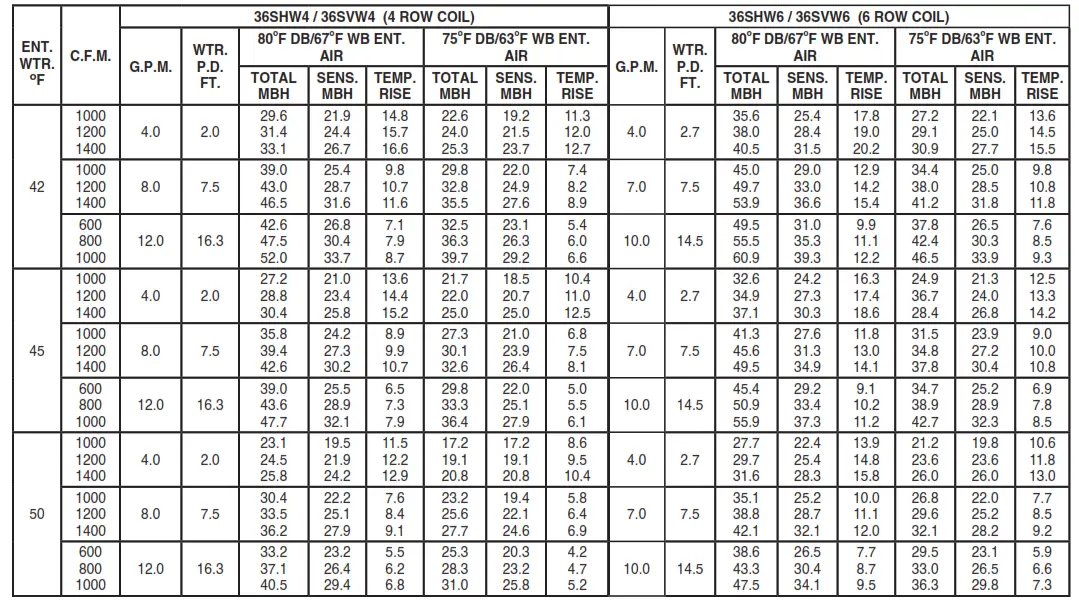
HOT WATER HEATING CAPACITIES
| 36SHW4 / 36SVW4 (4 ROW COIL) | |||||
| 180OF ENTERING WATER TEMPERATURE | |||||
| CFM | GPM | WTR. P.D. FT. | TOTAL MBH | LVG. AIR oF | LVG. WTR oF |
| 1000 1200 1400 | 4.0 | 2.0 | 75.5 83.9 91.7 | 140 135 131 | 142 138 134 |
| 1000 1200 1400 | 8.0 | 7.5 | 83.9 94.7 105.1 | 148 143 140 | 159 156 154 |
| 1000 1200 1400 | 12.0 | 16.3 | 86.8 98.9 110.1 | 150 146 143 | 165 163 162 |
| 36HWK (2 ROW COIL) | |||||
| 180OF ENTERING WATER TEMPERATURE | |||||
| CFM | GPM | WTR. P.D. FT. | TOTAL MBH | LVG. AIR oF | LVG. WTR oF |
| 1000 1200 1400 | 4.0 | 1.6 | 53.3 58.7 65.4 | 119 115 112 | 153 150 148 |
| 1000 1200 1400 | 8.0 | 6.1 | 59.4 66.2 72.5 | 125 121 118 | 165 164 162 |
| 1000 1200 1400 | 12.0 | 13.1 | 61.5 68.7 75.4 | 127 123 120 | 170 168 167 |
* 70 degree return air
Notes:
- See page 22 for hot water heating correction factors.
- Optional 6 row coils should not be used for heating.
- Optional 2 row hot water coils can be factory or field installed.
- When these units are used for hot water heating the leaving air temperature must not exceed 150 degrees.
At high altitude conditions, blower motor may cutout at a lower LAT. Contact factory for information.
48SVW
CHILLED WATER COOLING CAPACITIES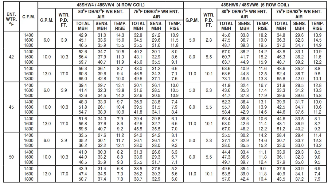
HOT WATER HEATING CAPACITIES
| 48SHW4 / 48SVW4 (4 ROW COIL) | |||||
| 180OF ENTERING WATER TEMPERATURE | |||||
| CFM | GPM | WTR. P.D. FT. | TOTAL MBH | LVG. AIR oF | LVG. WTR oF |
| 1400 1600 1800 | 6.0 | 3.9 | 106.3 114.9 123.3 | 140 137 133 | 145 142 139 |
| 1400 1600 1800 | 10.0 | 10.3 | 114.9 125.3 135.3 | 146 143 140 | 157 155 153 |
| 1400 1600 1800 | 13.0 | 17.0 | 118.0 129.4 140.0 | 148 145 142 | 162 160 158 |
| 48HWK (2 ROW COIL) | |||||
| 180ºF ENTERING WATER TEMPERATURE | |||||
| CFM | GPM | WTR. P.D. FT. | TOTAL MBH | LVG. AIR oF | LVG. WTR oF |
| 1400 1600 1800 | 5.0 | 2.0 | 72.8 78.0 82.7 | 118 115 113 | 151 149 147 |
| 1400 1600 1800 | 8.0 | 4.8 | 79.2 85.4 91.4 | 122 119 117 | 160 159 157 |
| 1400 1600 1800 | 12.0 | 10.4 | 83.3 90.2 97.0 | 125 122 120 | 166 165 164 |
* 70 degree return air
Notes:
- See page 22 for hot water heating correction factors.
- Optional 6 row coils should not be used for heating.
- Optional 2 row hot water coils can be factory or field installed.
- When these units are used for hot water heating the leaving air temperature must not exceed 150 degrees.
At high altitude conditions, blower motor may cutout at a lower LAT. Contact factory for information.
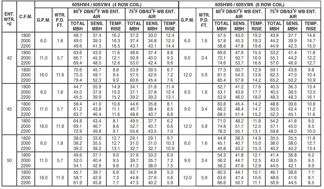
60SVW
CHILLED WATER COOLING CAPACITIES
HOT WATER HEATING CAPACITIES
| 60SHW4 / 60SVW4 (4 ROW COIL) | |||||
| 180ºF ENTERING WATER TEMPERATURE | |||||
| CFM | GPM | WTR. P.D. FT. | TOTAL MBH | LVG. AIR oF | LVG. WTR oF |
| 1800 2000 2200 | 6.0 | 1.8 | 128.0 136.2 143.8 | 136 133 131 | 137 135 132 |
| 1800 2000 2200 | 11.0 | 5.7 | 142.6 152.9 162.6 | 143 141 138 | 154 152 150 |
| 1800 2000 2200 | 16.0 | 11.6 | 149.6 160.8 171.4 | 147 144 142 | 161 160 159 |
| 60HWK (2 ROW COIL) | |||||
| 180ºF ENTERING WATER TEMPERATURE | |||||
| CFM | GPM | WTR. P.D. FT. | TOTAL MBH | LVG. AIR oF | LVG. WTR oF |
| 1800 2000 2200 | 6.0 | 3.1 | 93.1 98.2 103.1 | 118 116 113 | 149 147 145 |
| 1800 2000 2200 | 9.0 | 6.6 | 100.4 106.5 112.6 | 122 119 117 | 158 156 155 |
| 1800 2000 2200 | 12.0 | 11.5 | 104.4 111.0 117.7 | 124 121 120 | 163 162 160 |
* 70 degree return air
Notes:
- See page 22 for hot water heating correction factors.
- Optional 6 row coils should not be used for heating.
- Optional 2 row hot water coils can be factory or field installed.
- When these units are used for hot water heating the leaving air temperature must not exceed 150 degrees.
At high altitude conditions, blower motor may cutout at a lower LAT. Contact factory for information.
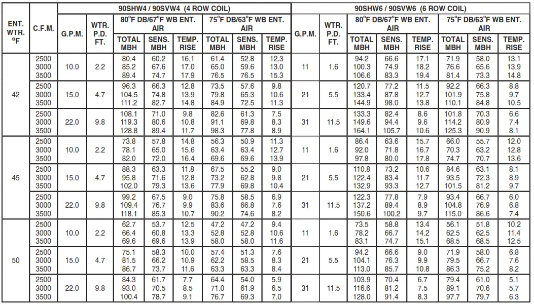
90SVW
CHILLED WATER COOLING CAPACITIES
HOT WATER HEATING CAPACITIES
| 90SHW4 / 90SVW4 (4 ROW COIL) | |||||
| 180ºF ENTERING WATER TEMPERATURE | |||||
| CFM | GPM | WTR. P.D. FT. | TOTAL MBH | LVG. AIR oF | LVG. WTR oF |
| 2500 3000 3500 | 10.0 | 2.2 | 207.8 232.4 255.2 | 147 142 137 | 138 133 129 |
| 2500 3000 3500 | 15.0 | 4.7 | 222.4 251.1 278.5 | 152 148 144 | 150 146 143 |
| 2500 3000 3500 | 22.0 | 9.8 | 232.8 265.1 295.7 | 156 152 148 | 159 156 153 |
| 90HWK (2 ROW COIL) | |||||
| 180ºF ENTERING WATER TEMPERATURE | |||||
| CFM | GPM | WTR. P.D. FT. | TOTAL MBH | LVG. AIR oF | LVG. WTR oF |
| 2500 3000 3500 | 8.0 | 1.0 | 146.2 160.5 171.5 | 124 120 115 | 143 140 137 |
| 2500 3000 3500 | 14.0 | 2.8 | 162.3 180.4 196.2 | 130 126 122 | 157 154 153 |
| 2500 3000 3500 | 21.0 | 6.1 | 171.1 191.2 209.1 | 133 129 125 | 164 162 160 |
* 70 degree return air
Notes:
- See page 22 for hot water heating correction factors.
- Optional 6 row coils should not be used for heating.
- Optional 2 row hot water coil can be factory installed in either the reheat (std.) or preheat positions.
- When these units are used with hot water coil the leaving air temperature must not exceed 150 degrees.
At high altitude conditions, blower motor may cutout at a lower LAT. Contact factory for information.
120SVW
CHILLED WATER COOLING CAPACITIES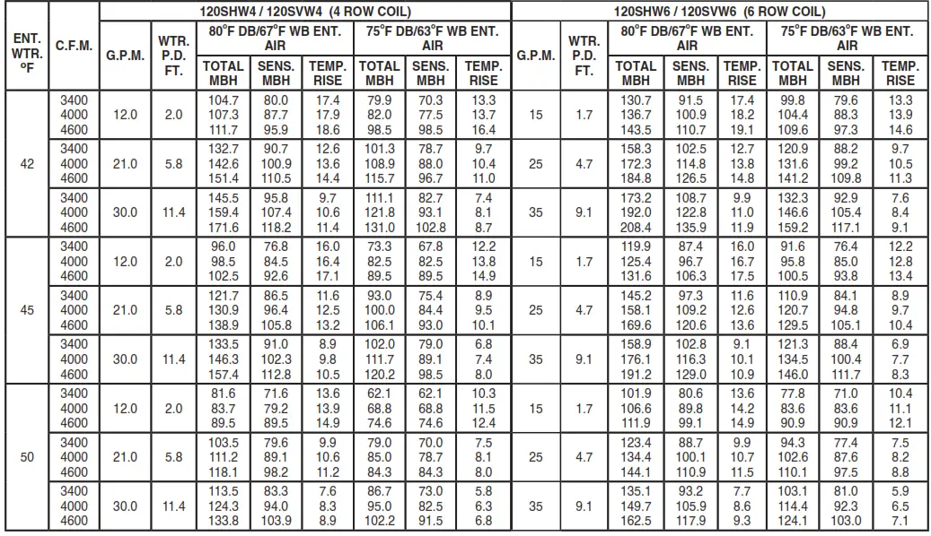
HOT WATER HEATING CAPACITIES
| 120SHW4 / 120SVW4 (4 ROW COIL) | |||||
| 180OF ENTERING WATER TEMPERATURE | |||||
| CFM | GPM | WTR. P.D. FT. | TOTAL MBH | LVG. AIR oF | LVG. WTR oF |
| 3400 4000 4600 | 12.0 | 2.0 | 273.2 302.6 328.3 | 144 140 136 | 135 130 125 |
| 3400 4000 4600 | 21.0 | 5.8 | 301.4 337.0 370.7 | 152 148 144 | 151 148 145 |
| 3400 4000 4600 | 30.0 | 11.4 | 314.4 352.9 389.8 | 155 152 148 | 159 156 154 |
| 120HWK (2 ROW COIL) | |||||
| 180ºF ENTERING WATER TEMPERATURE | |||||
| CFM | GPM | WTR. P.D. FT. | TOTAL MBH | LVG. AIR oF | LVG. WTR oF |
| 3400 4000 4600 | 11.0 | 1.0 | 198.5 215.8 229.4 | 124 120 116 | 144 140 138 |
| 3400 4000 4600 | 18.0 | 2.8 | 217.8 239.8 257.8 | 129 125 122 | 156 153 151 |
| 3400 4000 4600 | 25.0 | 5.3 | 227.8 251.9 272.0 | 132 128 125 | 162 160 158 |
* 70 degree return air
Notes:
- See page 22 for hot water heating correction factors.
- Optional 6 row coils should not be used for heating.
- Optional 2 row hot water coil can be factory installed in either the reheat (std.) or preheat positions.
- When these units are used with hot water coil the leaving air temperature must not exceed 150 degrees.
At high altitude conditions, blower motor may cutout at a lower LAT. Contact factory for information.
180SVW
CHILLED WATER COOLING CAPACITIES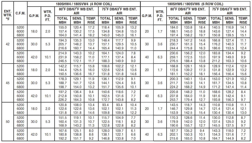
HOT WATER HEATING CAPACITIES
| 180SHW4 / 180SVW4 (4 ROW COIL) | |||||
| 180ºF ENTERING WATER TEMPERATURE | |||||
| CFM | GPM | WTR. P.D. FT. | TOTAL MBH | LVG. AIR oF | LVG. WTR oF |
| 5200 6000 6800 | 18.0 | 2.0 | 411.0 449.4 483.2 | 143 139 136 | 134 130 126 |
| 5200 6000 6800 | 30.0 | 5.3 | 450.7 496.9 540.5 | 150 147 143 | 150 147 144 |
| 5200 6000 6800 | 42.0 | 10.1 | 471.7 521.8 570.0 | 154 150 148 | 157 155 153 |
| 180HWK (2 ROW COIL) | |||||
| 180ºF ENTERING WATER TEMPERATURE | |||||
| CFM | GPM | WTR. P.D. FT. | TOTAL MBH | LVG. AIR oF | LVG. WTR oF |
| 5200 6000 6800 | 17.0 | 1.9 | 308.7 332.3 352.6 | 125 121 118 | 144 141 138 |
| 5200 6000 6800 | 25.0 | 4.1 | 332.3 360.2 386.1 | 129 125 123 | 153 151 149 |
| 5200 6000 6800 | 35.0 | 8.0 | 347.8 378.5 407.5 | 132 128 125 | 160 158 157 |
* 70 degree return air
Notes:
- See page 22 for hot water heating correction factors.
- Optional 6 row coils should not be used for heating.
- Optional 2 row hot water coil can be factory installed in either the reheat (std.) or preheat positions.
- When these units are used with hot water coil the leaving air temperature must not exceed 150 degrees.
At high altitude conditions, blower motor may cutout at a lower LAT. Contact factory for information.
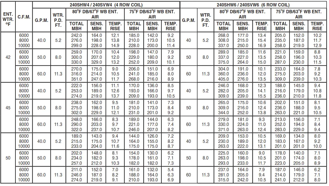
240SVW
CHILLED WATER COOLING CAPACITIES
HOT WATER HEATING CAPACITIES
| 240SHW4 / 230SVW4 (4 ROW COIL) | |||||
| 180OF ENTERING WATER TEMPERATURE | |||||
| CFM | GPM | WTR. P.D. FT. | TOTAL MBH | LVG. AIR oF | LVG. WTR oF |
| 6000 8000 10000 | 40.0 | 5.2 | 547 664 768 | 154 147 141 | 153 147 142 |
| 6000 8000 10000 | 50.0 | 8.0 | 561 687 799 | 157 150 144 | 158 153 |
| 6000 8000 10000 | 60.0 | 11.3 | 571 702 819 | 158 151 146 | 161 157 153 |
| 240HWK (2 ROW COIL) | |||||
| 180ºF ENTERING WATER TEMPERATURE | |||||
| CFM | GPM | WTR. P.D. FT. | TOTAL MBH | LVG. AIR oF | LVG. WTR oF |
| 6000 8000 10000 | 15.0 | 0.9 | 323 369 415 | 120 113 108 | 137 131 125 |
| 6000 8000 10000 | 25.0 | 2.3 | 361 420 457 | 126 119 112 | 151 146 144 |
| 6000 8000 10000 | 35.0 | 4.3 | 382 449 494 | 192 122 116 | 158 154 152 |
* 70 degree return air
Notes:
- See page 22 for hot water heating correction factors.
- Optional 6 row coils should not be used for heating.
- Optional 2 row hot water coil can be factory installed in either the reheat (std.) or preheat positions.
- When these units are used with hot water coil the leaving air temperature must not exceed 150 degrees.
At high altitude conditions, blower motor may cutout at a lower LAT. Contact factory for information.
HOT WATER HEATING CORRECTION FACTORS
| ENTERING AIR TEMP. (ºF) | ENTERING WATER TEMPERATURE (ºF) | ||||||||
| 100 | 110 | 120 | 130 | 140 | 150 | 160 | 170 | 180 | |
| 50 | 0.455 | 0.545 | 0.636 | 0.727 | 0.818 | 0.909 | 1.000 | 1.091 | 1.182 |
| 55 | 0.409 | 0.500 | 0.591 | 0.682 | 0.773 | 0.864 | 0.955 | 1.045 | 1.136 |
| 60 | 0.363 | 0.455 | 0.545 | 0.636 | 0.727 | 0.818 | 0.909 | 1.000 | 1.091 |
| 65 | 0.318 | 0.409 | 0.500 | 0.591 | 0.682 | 0.773 | 0.864 | 0.955 | 1.045 |
| 70 | 0.272 | 0.363 | 0.455 | 0.545 | 0.636 | 0.727 | 0.818 | 0.909 | 1.000 |
| 75 | 0.227 | 0.318 | 0.409 | 0.500 | 0.591 | 0.682 | 0.773 | 0.864 | 0.955 |
| 80 | 0.182 | 0.272 | 0.363 | 0.455 | 0.545 | 0.636 | 0.727 | 0.818 | 0.909 |
Notes:
- To determine heating capacity at other than 180 deg. E.W.T. and 70 deg. E.A.T. multiply the selected heating capacity at 180 deg. times the appropriate correction factor from above chart.
- These correction factors may be used on all First Co. published 180 deg. heating capacities.
- When SHW units are used for hot water heating the leaving air temperature must not exceed 150 degrees. At high altitude conditions, blower motor may cutout at a lower LAT. Contact factory for information.
AWARNING AVERTISSEMENT ADVERTENCIA Cancer and Reproductive Harm www.p65Warnings.ca.gov
LBY0057
GUIDE SPECIFICATIONS
Furnish and install First Co. SVW Series Blower – Coil units as indicated on the plans.
CABINETS
Cabinets shall be manufactured of heavy gauge galvanized steel. The entire interior of the cabinet shall be insulated with one inch thick IAQ type insulation. Removable access panels shall be provided on both sides of the cabinet for maintenance and service. All cabinets shall have 2” supply and 1” return flanges.
INSULATION
The entire interior of the cabinet shall be insulated with one (1) inch insulation. This insulation must meet the requirements of ASTM C 1071, ASTM G 21, ASTM G 22, NFPA 90A, UL-181, and the cleaning practices of NAIMA.
MOTOR / BLOWERS
Blowers shall be resiliently mounted, with ball bearings, forward curved blade, and of centrifugal type. Each wheel shall be dynamically balanced for smooth, quiet operation. Blowers shall be belt driven with field adjustable pulleys to permit variations in static pressure and air requirements. Standard motors are 1725 RPM either single or three phase. All motors to be field or factory installed and wired at voltage specified by customer.
COILS
All SVW series coils shall consist of aluminum fins mechanically bonded onto 3/8” or 1/2” OD seamless copper tubing. All coils shall be leak tested at 350 PSIG minimum air pressure. Manual air vents shall be standard on all coils.
Drain pans shall be coated for corrosion protection.
FILTERS
One inch throw away filters are standard in 2-5 ton SVW units. One inch permanent filters are provided as standard in 7-20 ton SVW units. Filters shall be accessible without tools.
LISTING
All standard motors are ETL Listed. All air handlers shall be rated in accordance with ARI Standard 430. Standard motors have internal overload protection. Therefore, units shipped with standard motors will be ETL listed. Most non-standard motors (i.e. 575V, 2-speed, TEFC, some 50 Hz., etc.) are not available with internal overload protection. Therefore, most units shipped with non-standard motors can be ETL listed with the addition of a factory installed motor starter (contact the factory for starter information and ETL verification.)
![]() FIRST CO.
FIRST CO.
P.O. BOX 270969 – DALLAS, TEXAS 75227
PH. (214) 388-5751 | [email protected]
WWW.FIRSTCO.COM


