![]() RV-10000 Vibrio Rheometer
RV-10000 Vibrio Rheometer
Instruction Manual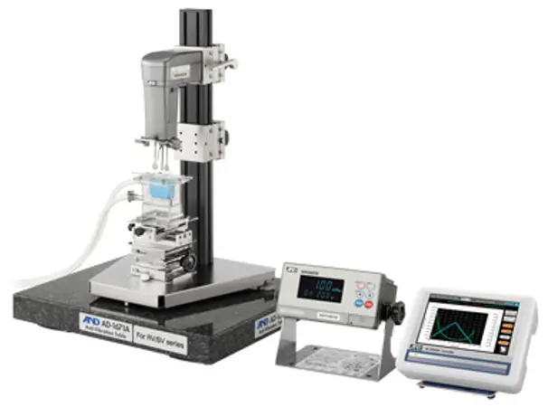
RV 10000
Vibrio Rheometer
-INSTRUCTION MANUAL
RV-10000 Vibrio Rheometer
© 2013 A&D Company Ltd. All rights reserved.
No part of this publication may be reproduced, transmitted, transcribed, or translated into any language in any form by any means without the written permission of A&D Company Ltd.
The contents of this manual and the specifications of the instrument covered by this manual are subject to change for improvement without notice.
INTRODUCTION
This manual describes how the rheometer RV-10000 works and how to get the most out of it in terms of performance.
Read this manual thoroughly before using the rheometer and keep it at hand for future reference.
1-1 Compliance
Compliance with FCC Rules
Please note that this device generates, uses and can radiate radio frequency energy. This device has been tested and has been found to comply with the limits of a Class A computing device pursuant to Subpart J of Part 15 of FCC rules. These rules are designed to provide reasonable protection against interference when this device is operated in a commercial environment. If this unit is operated in a residential area, it may cause some interference and under these circumstances the user would be required to take, at his own expense, whatever measures are necessary to eliminate the interference.
(FCC = Federal Communications Commission in the U.S.A.)
Compliance with Council Directives This device features radio interference suppression and safety regulation in compliance with the following Council Directives
Council directive 89/336/EEC EN61326 EMC directive
Council directive 73/23/EEC EN60950 Safety of Information Technology Equipment![]() EN61326 Emission and Immunity.
EN61326 Emission and Immunity.
Note
The CE mark is an official mandatory European marking.
Please note that any electronic product must comply with local laws and regulations when sold or used anywhere outside Europe.
1-2 Features
- High accuracy
The Vibrio Rheometer adopting the sine-wave vibration technique, achieves a high measurement accuracy of 1% (repeatability) over the full range. - Because amplitude with the sensor plates can be changed, viscosity change can be measured by change in shear speed.
- The sensor plates are made of corrosion resistant titanium. Although titanium is a chemically stable material, it is corroded by some liquid such as sulfuric acid. So, handle it with much care.
- Wide range continuous measurement
Continuous measurement over the whole measuring range is possible, without replacing the viscosity detection sensor plates. - Standard temperature sensor
The temperature sensor to measure the sample temperature is installed as standard. The temperature sensor is located between the two sensor plates. So, the accurate detection of the relation between temperature and viscosity is possible. - Accurate measurement
Due to the low heat capacity of the viscosity detection unit (sensor plates and temperature sensor), the time required for temperature equilibrium is short. Thus, the sample viscosity can be measured accurately in a short time. - Long continuous measurement time
The sensor plates, with a low frequency of 30 Hz, apply very little load to the sample. So, the rheometer can continuously obtain stable viscosity values without causing a temperature rise or damaging the sample. - The sine-wave vibrio rheometer (viscometer) measures “viscosity x density”. While viscosity (mPa.s) is used as the unit for measuring, this is displayed assuming that density is 1g/cm3.
- Measurement of a non-Newtonian fluid/foaming sample
The thin sensor plates allow little deformation of the sample texture. Thus, non-Newtonian fluid can be measured in a stable way. And, foaming samples (whipped cream, etc.)) can be measured without breaking minute foam particles and with less influence scattering large foam particles.
When measuring tap water, bubbles may accumulate on the sensor plates, increasing the viscosity. - Viscosity measurement of a flowing sample
The two sensor plates oscillate in the opposite direction. So, even when a sample is in motion, errors are eliminated. This allows measurement of a sample while being stirred. Therefore, the rheometer can be used for a continuously flowing product line, which enables field management with identical data used at the laboratories. - Calibration
The rheometer can be calibrated using a standard viscosity fluid or a sample of a known viscosity. Calibration allows the rheometer to maintain the accuracy constantly. - Simplified calibration when measuring the viscosity near 1 maps
Simplified calibration using purified water is a one-key operation. The rheometer has a built-in function to measure the temperature of the purified water using the temperature sensor and calculates the viscosity value of the purified water at that temperature. At this time, be careful not to influence the viscosity value by generating bubbles. - Standard windows communication tools Win CT-Viscosity
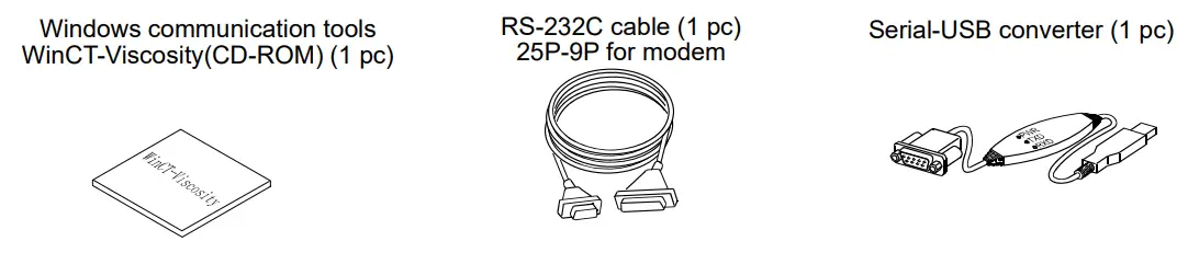
Windows communication tools Win Ct-Viscosity (CD-ROM) is provided as standard. The CD-ROM contains the graphing program Viscous, which imports the data into a personal computer and displays the results as a graph in real time. With Viscous, changes in viscosity over time and temperature dependency of viscosity can be observed easily and the obtained data can be saved in files. - When using the accessory serial / USB converter, the personal computer can input the data using the personal computer’s USB port.
- The cup, that the sample is to be measured in, can be the plastic sample cup and the glass sample cup. When measuring an organic solvent, use the glass sample cup.
UNPACKING THE RHEOMETER
- The rheometer is a precision instrument. Unpack the rheometer carefully. Keep the packing material to be used for transporting the rheometer in the future.
2-1 Part names
*The illustration below is after assembling.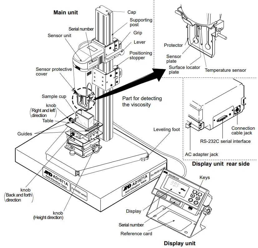
Accessories
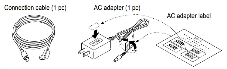
Note
Please confirm that the AC adapter type is correct for your local voltage and receptacle type.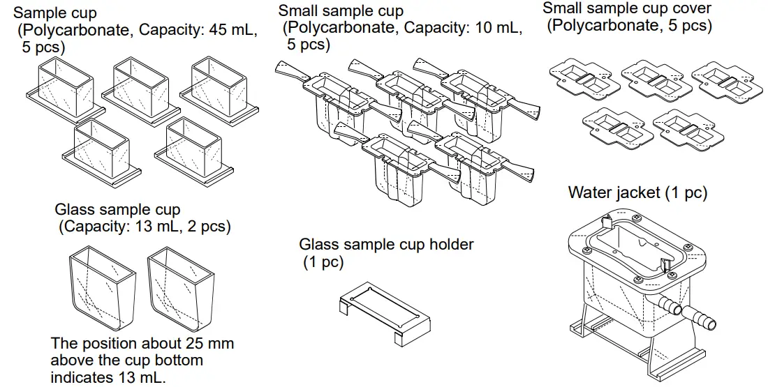
DISPLAY AND KEYS
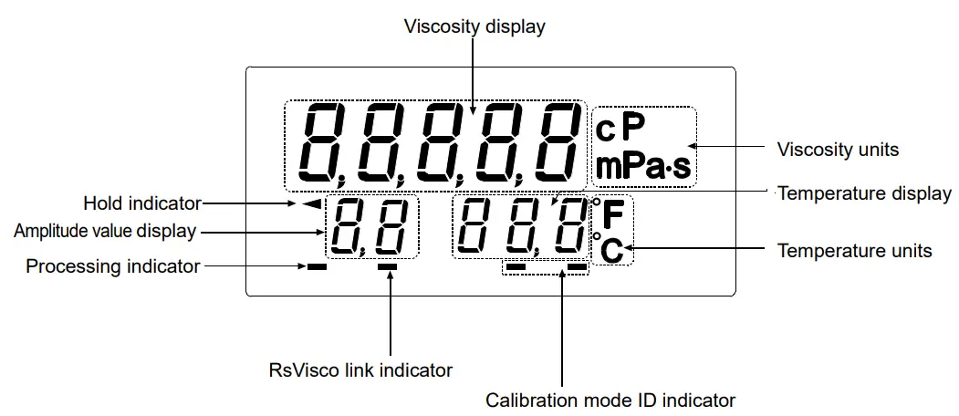
3-1 Display
| Name | Description | |||
| Viscosity display | Standby mode | Displays [——- ]. | ||
| Measurement mode | Displays the viscosity value in real time. | |||
| Viscosity units | Displays the unit of viscosity. | |||
| Temperature display | Standby mode | Displays the temperature value in real time. | ||
| Measurement mode | ||||
| Temperature units | Displays the unit of temperature. | |||
| Processing indicator | Blinks while the measurement is being performed. (While the sensor plates are in vibrating motion) | |||
| Rs Viscos link indicator | Illuminates while measurement is performed using Rs Viscos, the graphing program contained in the Win CT-Viscosity (CD-ROM). | |||
| Calibration indicator | Displays ” C ” in the calibration mode. | |||
| Calibration mode ID indicator | At one-point calibration | Blank display [ ] | ||
| At two-point calibration | Inputting first point | Displays [ – ]. | ||
| Inputting second point | Displays [ – – ]. | |||
| Amplitude value display | Displays the amplitude value. | |||
3-2 Keys
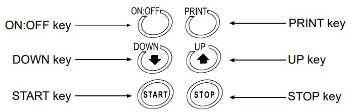
Key | Description |
ON:OFF | Turns the power on and off. When the power is turned on, the rheometer enters the standby mode ( [——- ] is displayed.) |
START | Start a measurement. (The processing indicator blinks.) Displays the viscosity and temperature values in real time during measurement. |
| If the display is set to HOLD, release it by pressing the START key. | |
STOP | Stops the measurement (The processing indicator is off) and freezes the display of the viscosity and temperature values at the time the STOP key is pressed during measurement. When the STOP key is pressed again, the rheometer enters the standby mode. |
| Press and release: Decreases the amplitude value gradually. Press and hold: Enters the calibration mode. |
| Press and release: Increases the amplitude value gradually. Press and hold: Puts into function setting mode. |
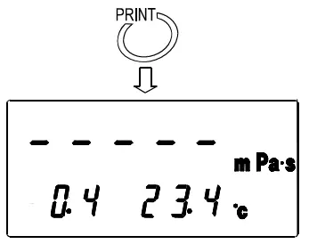
PRINT | Outputs the measurement data. |
3-3 Displaying the Viscosity Values
The viscosity values are displayed as below, depending on the unit selected and the viscosity range.
The correlation of the units are as follows: 1 mPa×s = 0.001 Pa.s = 1 cpm =0.01 P
It is possible to switch between mPa×s (Millipascal second) and Pa.s (Pascal second), or between cpm (Centipoise) and P (Poise), using the function setting. (Refer to “8. FUNCTION SETTING”)
The unit selected at the factory before shipment is mPa×s.
When the viscosity unit is mPa×s or Pa.s:
| Viscosity measured mPa×s | Unit selected | |||||||
| mPa×s | Pa×s | |||||||
| Display | Minimum display | Unit | Remarks | Display | Minimum display | Unit | Remarks | |
| 10 | 0.30 | 1.00 | 9.99 10.0 | 99.9 | 0.01 | mmPa×s | 0.0003 0.0010 0.0099 0.0100 0.0999 | 0.0001 | Pa×s | Digit indicating 0.01 mPa×s is not displayed | |
| 100 | 100 | 0.100 | ||||||
| | | 1 | 0.001 | ||||||
| 999 | 0.999 | |||||||
| 1000 10000 | 1.00 | 10.00 | 0.01 | Pa×s | Switches to Pa×s | 1.00 | 10.00 | 0.01 | ||
When the viscosity unit is cpm or P:
| Viscosity measured mPa×s | Unit selected | |||||||
| cP | P | |||||||
| Display | Minimum display | Unit | Remarks | Display | Minimum display | Unit | Remarks | |
| 1 10 100 1000 10000 | 0.30 | 1.00 | 9.99 10.0 | 99.9 100 | 999 | 0.01 | cpm | 0.0030 | 0.0100 | 0.0999 0.100 | 0.999 1.00 | 9.99 10.0 | 100.0 | 0.0001 0.001 | P | ||
| 10.0 | 100.0 | 0.1 | P | Switches to P | |||||
PRECAUTIONS
To get the optimum performance from the rheometer and acquire accurate measurement data, note the following:
4-1 General Precautions
For accurate measurement, use care with the following conditions.
- Install the rheometer in an environment where the temperature and humidity are not excessive.
The best operating temperature is 25°C2°C at 45-60% relative humidity. - For precise measurement, install the rheometer where there are no great changes in temperature and humidity.
- Install the rheometer where it is free of dust.
- The rheometer uses the Tuning-fork Vibration Method. So, use much care to avoid external vibration, especially when measuring low viscosity.
Places where the rheometer is prone to vibration are: Second or higher floor, soft ground, near busy highways or rail lines.
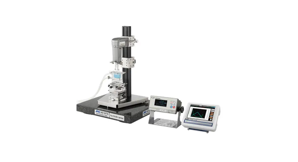
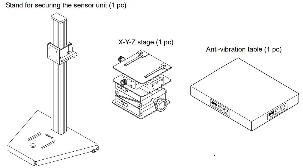
Avoid these places as a measuring site. If measurement is to be performed in such a place, use an anti-vibration table that is available as an option (AD-1671A). - Do not measure where heaters or air conditioners can affect the measurement.
- Do not measure where direct sunlight can affect the measurement.
- Install the rheometer away from equipment which produces magnetic fields.
- Protect the internal parts from liquid spills and excessive dust.
- Do not disassemble the rheometer.
- When precise measurement is required, acclimatize the rheometer to the measuring environment. After installation, plug in the AC adapter and warm up the rheometer for one hour or more.
4-2 During Use
- The RV-10000 rheometer, designed for very accurate measurement, is sensitive to vibration or shock during transportation, as that may cause a display value error. Before measurement, calibrate the rheometer using the sample cup that will be used for measurement.
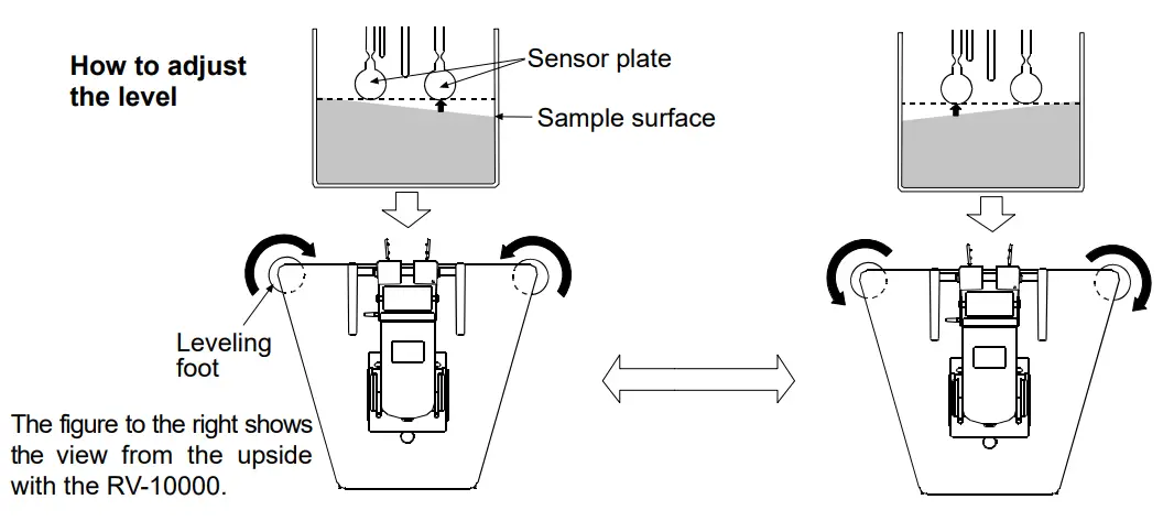
- To level the surface of the sample, adjust the leveling feet. (Height adjustment of the right and left leveling feet.)
- In general, a viscosity value with a liquid changes in accordance with temperature change (In general, if increasing the temperature, the viscosity value decreases about 2 to 10 percent per degree Celsius). Take changes in the liquid temperature into consideration for an accurate measurement.
- Be sure to calibrate using the standard viscosity fluid or purified water before measurement. In a measurement that takes a long time, perform calibration periodically, as necessary.
- Ensure a stable power source when using the AC adapter.
- Placing the sensor plates and the temperature sensor in the sample may change the sample temperature. For precise measurement, leave the sample as is for a while, after placing the sensor plates and the temperature sensor, to ensure no changes to the sample temperature. And then, start a measurement.
- Use only your finger to press the keys. Using a sharp instrument such as a pen may damage keys.
- Handle the sensor plates with care.
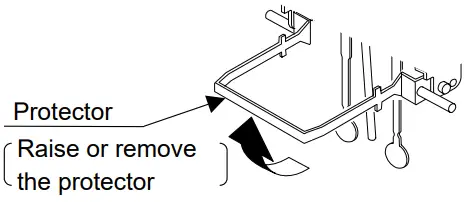
- If the sensor plates, or the protector, touch the inner wall of the sample cup, it may cause measurement error. When measuring, be sure to adjust the spacing between the sensor plates and the inner walls of the sample cup.
- The sample cups are made of polycarbonate (PC) or glass. When using organic solvents, we recommend the use of the glass sample cup (accessory or sold separately) or a commercially available glass beaker.
Raise or remove the protector if necessary.
Precautions to be taken with the sample cup used
When the sample cup for measuring is changed, that may cause a change in the displayed viscosity value. Therefore, we recommend that you calibrate the rheometer using standard viscosity fluid. (Refer to “6-4. Measuring the Absolute Value of Viscosity Using the Small Sample Cup” for details.)
How to remove the protector:
Press the left and right side frames lightly in the direction indicated as 1 to remove the rotational axis. Pull the protector in the direction indicated as 2 to remove.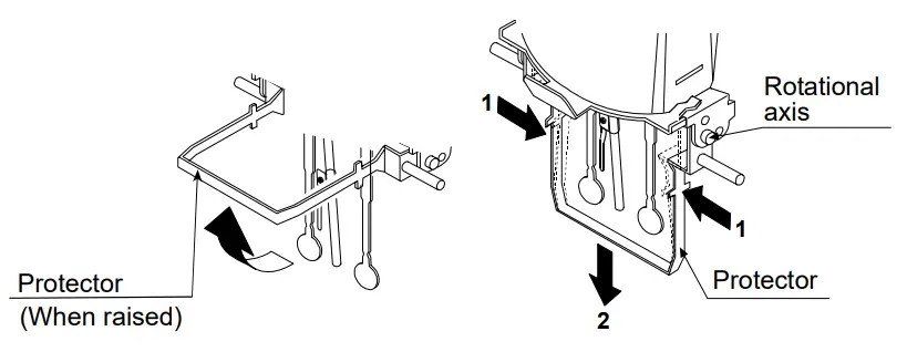
4-3 After Use
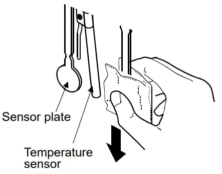
- Remove any residual sample material from the sensor plates, temperature sensor and protector using alcohol. Using the sensor plates, temperature sensor and protector with residue of an old sample left on will cause a measurement error. Clean the sensor plates carefully to avoid bending them. The sensor plates and the temperature sensor are made of titanium.
How to clean the sensor plates and temperature sensor
Hold the sensor plate or temperature sensor with tissue paper.
Move the tissue paper downward to remove the sample.
Then, use tissue paper moistened with alcohol, to remove any residual sample material.
- Clean the sample cup as necessary.
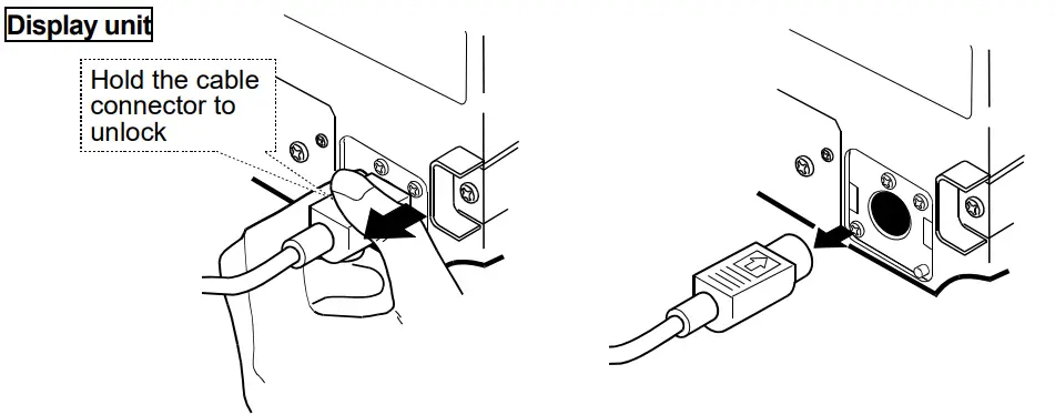
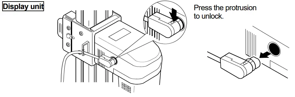
- Unlock the cable connector before disconnecting the connection the cable. How to unlock the cable connector
4-4 About viscosity measured with the RV
When the sample cup for measuring is not a sample cup with 45mL capacity, viscosity will change at a value where viscosity is several thousand mPa×s or more. Therefore, calibrate using standard viscosity fluid by the cup used.
The RV-10000 Sine-wave Vibrio Rheometer, as a measuring principle, detects the product of viscosity and density (defined as “static viscosity”)..
Static viscosity = Viscosity x Density …………. [1]
While the displayed value has a unit of mPa×s, it indicates the product of viscosity and density.
Example (1) When a sample has a viscosity of 2.00 mPa×s and density of 1.000:
Displayed value = 2.00 [mPa×s] x 1.000 = 2.00 [mPa×s]
(2) When a sample has a viscosity of 2.00 mPa×s and density of 0.800:
Displayed value = 2.00 [mPa×s] x 0.800 = 1.60 [mPa×s]
Note
The density can be measured, using the density determination kit, AD-1653 in combination with a balance.
To obtain the absolute viscosity value precisely, do as follows:
4-4-1 At Measurement
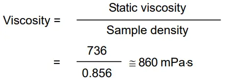
Divide the static viscosity by the sample density to obtain the viscosity.
Example (1) Measure the sample and confirm the static viscosity.
Here, 736 mPa×s as an example.
(2) Check the sample density at the temperature when the sample is measured.
Here, 0.856 as an example.
(3) Divide the static viscosity by the sample density to obtain the viscosity.
Here, 860 mPa×s is obtained as the viscosity.
4-4-2 At Calibration
When calibrating, enter the product of the absolute viscosity value and the density of the standard viscosity fluid used for calibration, as a correction value.
The standard viscosity fluid has the calculation sheet of kinetic viscosity and viscosity at various temperatures attached. To obtain the correction value using this sheet, do as follows: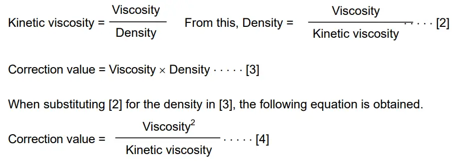
Example 1: To calibrate the rheometer using a standard viscosity fluid:
Using the calculation sheet, calculate the value used for calibration.
(1) Check the kinetic viscosity and the viscosity at the temperature when the calibration is performed. Here, 1011 mm2/s for the kinetic viscosity and 889 mPa×s for the viscosity at 20°C as an example.
(2) Substitute the values above into equation [4].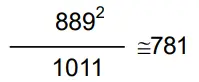 781 mPa.s is obtained as a correction value used for calibration.
(3) After calibration, measure the viscosity of the standard viscosity fluid used. In this example, a value similar to “781 mPa×s” is confirmed as static viscosity, and calibration
then ends.
Example 2: To calibrate using a standard viscosity fluid with known values of viscosity and density.
In this example, a standard viscosity fluid with a viscosity of 889 mPa×s at 20°C is used.
- Check the viscosity value and the density of the standard viscosity fluid at the temperature when the calibration is performed.. Here, 889 mPa×s for the viscosity and 0.878 for the density at 20°C as an example.
- Substitute the values above into equation [3]. 889 x 0.878 x 781 781 mPa×s is obtained as a correction value used for calibration.
- After calibration, measure the viscosity of the standard viscosity fluid used. In this example, a value similar to “781 mPa×s” is confirmed as static viscosity, and calibration then ends.
4-5 About the relation among amplitude value, shear speed and viscosity
When measuring with a non-Newtonian fluid, a viscosity can not be judged without deciding a value for shear speed or shear stress because there is no proportional relation between shear speed and shear stress.
When measuring with the RV-10000, vibration is repeatedly applied to the sample using sine vibration, and viscosity is expressed by converting into an effective value the shear speed that is constantly changing due to vibration.
Refer to the following charts for details of the relation among amplitude value, shear speed and viscosity with the RV-10000.
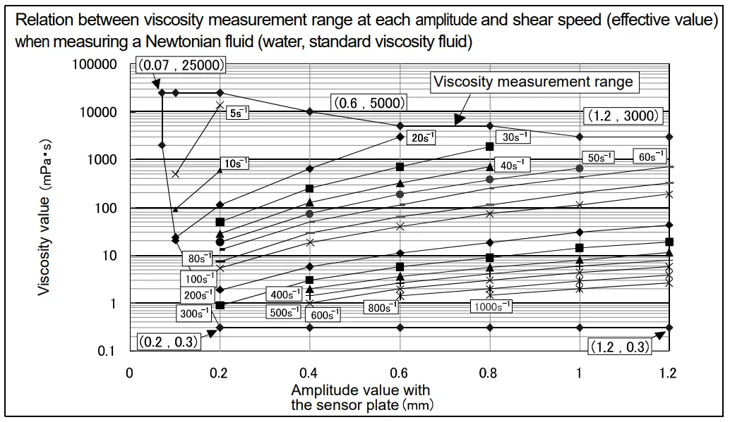
The second chart below shows the relation between the viscosity measurement range at each amplitude and shear speed.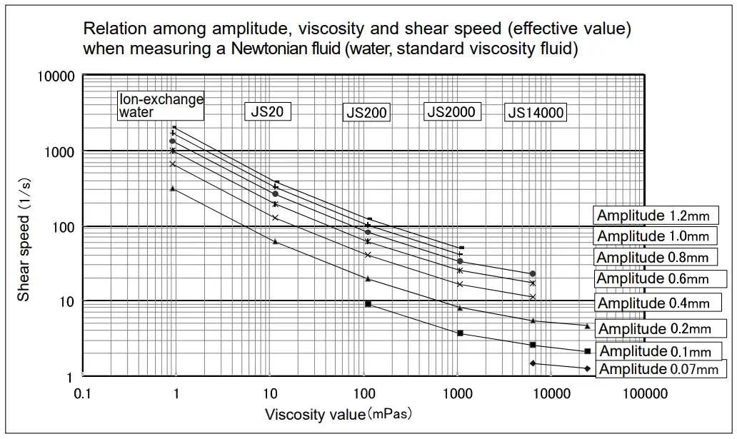
MEASUREMENT
5-1 Preparing the Sample
* Vibration or shock during transportation may cause a display value error. Before measurement, calibrate the rheometer using the sample cup that will be used for measurement. For calibration with purified water, refer to “7-2-3 Simplified Calibration Using Purified Water”.
Operation procedure
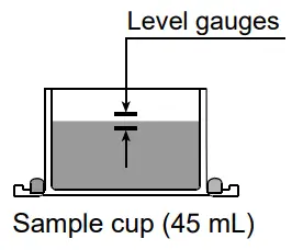
- Pour the sample into the cup until its surface is between the level gauges.
– With the 45 mL sample cup, the lower level gauge indicates 35 mL, the upper level gauge indicates 45 Mr.
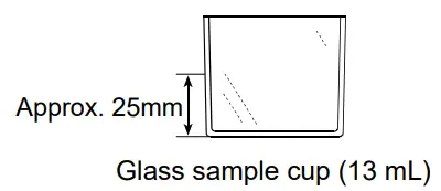
– The 13 mL glass sample cup does not have level gauges.
The position approximately 25 mm above the cup bottom indicates 13 Mr.

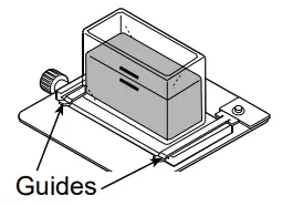
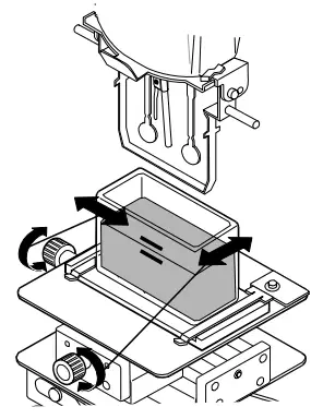
- Attach the cup on the table along the guides.

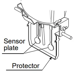
- Confirm that the protector is in the position as shown in the figure.
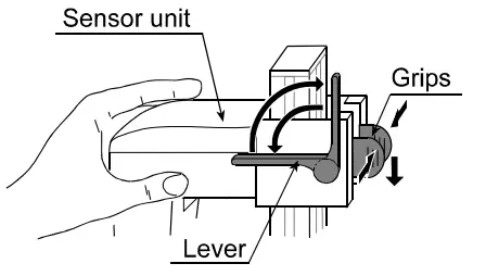
Raise the lever to release the sensor unit.
- Pinch the grips, support the front side of the sensor unit and gently lower the sensor plates above the sample surface.

- Lower the lever to secure the sensor unit.

- Confirm that the positioning of the sensor plates is in center of the sample cup by adjusting the X-Y-Z stage.
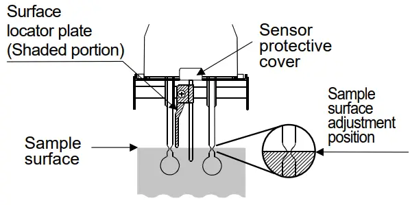
- Turn the knob (Height direction) so as to adjust the sample surface to the center of the narrow part of the sensor plates. At this time, use the surface locator plate as a guide. The surface locator plate has been secured in position so that the tip of the surface locator plate comes into contact with the sample surface.

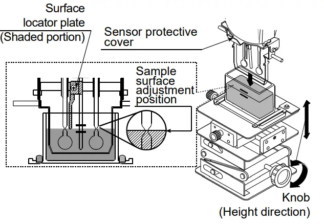
Note
- Adjust the height of the sample surface correctly, otherwise it may cause a measurement error.
- The surface locator plate can be attached or removed by loosening the screw.
- Before removing the sensor protective cover, remove the surface locator plate.
- Removing and reattaching the surface locator plate will cause the position (Height) of the sensor plates and the sample surface to change. Therefore, it is recommended
that calibration be performed using a standard viscosity fluid before measurement.
Note
Use the protector in the position as shown on the left below. If the protector is not used, a measurement error may occur, especially in measuring a viscosity over 5000 mPa×s.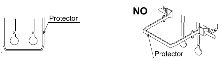 When the position of the sensor plates in the liquid is not at the same level, level the rheometer using the leveling feet so that the liquid surface will be leveled.
5-2 Basic measurement
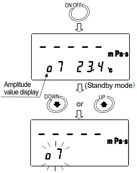
5-2-1. Setting amplitude value
- With the power off, press the ON:OFF key.

- Once the display is in standby mode, press the
 key.
key. - The amplitude value display blinks.
- By pressing
 key, the amplitude value increases.
 - By pressing
 key, the amplitude value decreases.
- Press the PRINT key at the desired amplitude value to confirm the amplitude value.
(Even if the START key is pressed, the amplitude value will be confirmed. After that, vibration is started.)
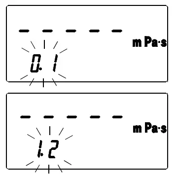
Settable range of amplitude
| Amplitude * | Amplitude value display |
| 0.07mm | o7 |
| 0.1mm | 0. 1 |
| 0.2mm | 0. 2 |
| 0.4mm | 0.4 |
| 0.6mm | 0.6 |
| 0.8mm | 0. 8 |
| 1.0mm | 1 .0 |
| 1.2mm | 1 . 2 |
* The amplitude value is peak to peak (P-P).
5-2-2. Measurement
1. Starting measurement
Press the START key to start vibration. The viscosity value is displayed after approx. 15 seconds. While measurement is being carried out, the processing indicator illuminates.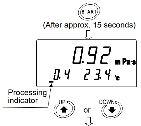 (2) Changing the amplitude during measurement
- Even while the measurement is being carried out, it is possible to change the amplitude by pressing the key. If the display blinks. key is pressed, the amplitude

- By further pressing the key, the amplitude value changes.
- Press the PRINT key at the desired amplitude value to confirm the amplitude value.

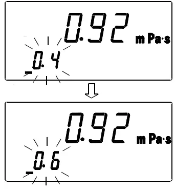
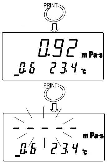
When an amplitude is changed, the bar display blinks. The amplitude value is displayed after approx. 15 seconds.
(3) Stopping measurement
Press the STOP key to stop the measurement. The viscosity value is held.
(4) Measuring again 1
When measuring again at the amplitude value where the measurement was stopped, press the key without making any changes. The measurement starts at the amplitude value where START the measurement was stopped.
(5) Measuring again 2
When measuring with a different amplitude value from the amplitude value where the measurement was stopped, first press the ![]() key. The amplitude value display will start to blink. Confirm the change to the amplitude value (Refer to “5-2-1. Setting amplitude value”), and then press the START key to start the measurement.
key. The amplitude value display will start to blink. Confirm the change to the amplitude value (Refer to “5-2-1. Setting amplitude value”), and then press the START key to start the measurement.
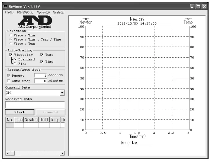
5-2-3. Measurement when using WinCT-Viscosity
It is possible to acquire viscosity or temperature data at each amplitude.
(1) How to use
- Install Win CT-Viscosity (For details of the installation, refer to Readme in the CD-ROM. Win CT-Viscosity can be used with the RV-10000 in addition to the SV series. When reading contents noted in Win CT-Viscosity, replace “SV” with “RV-10000”.).
- Start Viscous in Win CT-Viscosity.

- Confirm the amplitude value using the RV-10000. (Refer to “5-2-1. Setting amplitude value“)
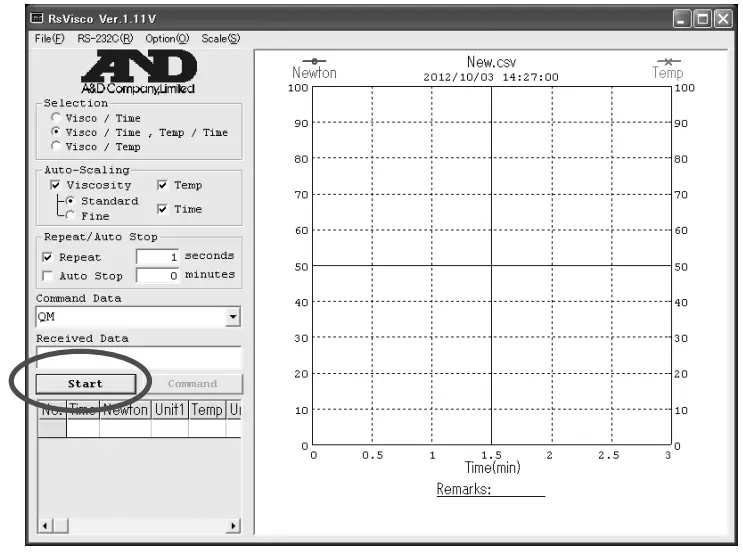
- Press the Start button in Rs Viscos to start the measurement. Data acquisition starts after approx. 15 seconds.

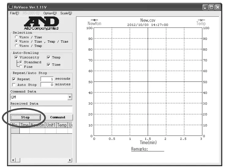
(2) Precautions to be taken when acquiring data with changed amplitude
When acquiring data with changed amplitude, first press the Stop button in Rs Viscos to end the measurement, and then change the amplitude value with the RV-10000.
- Press the Stop button in Rs Viscos to end the measurement.

- Confirm the amplitude value on the RV-10000. (Refer to “5-2-1. Setting amplitude value“)
- Press the Start button in Rs Viscos to start the measurement.
USING THE WATER JACKET
6-1. Introduction
The water jacket, is used with the rheometer RV-10000, to maintain the sample temperature constant or to measure the viscosity when the sample temperature is changed. The operating temperature range is 0°C to 100°C
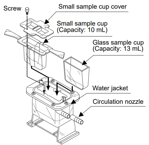
The water jacket consists of the following:
Water jacket 1 pc (Main body: PC (Polycarbonate), Packing: Silicone rubber, Washer: Nylon)
Screw 1 pc (Screw: POM (Polyacetal), Washer: Nylon)
Note
- As a heating medium, use water, isopropyl alcohol (IPA), mixture of water and IPA, or silicone oil, which does not erode the materials described above. Using the heating medium other than these may damage the water jacket.
- When using the water jacket, make sure that no inner pressure is exerted in the water jacket due to the kinked or blocked tubes, as that could exert the pressure in the water jacket, causing it to break.
- To control the temperature, a commercially available constant temperature bath is required separately.
6-2. Installation
Use the small sample cup (capacity: 10 mL) provided or the glass sample cup (capacity: 13 mL) provided.
To circulate the heating medium into the water jacket, a commercially available constant temperature bath is required.
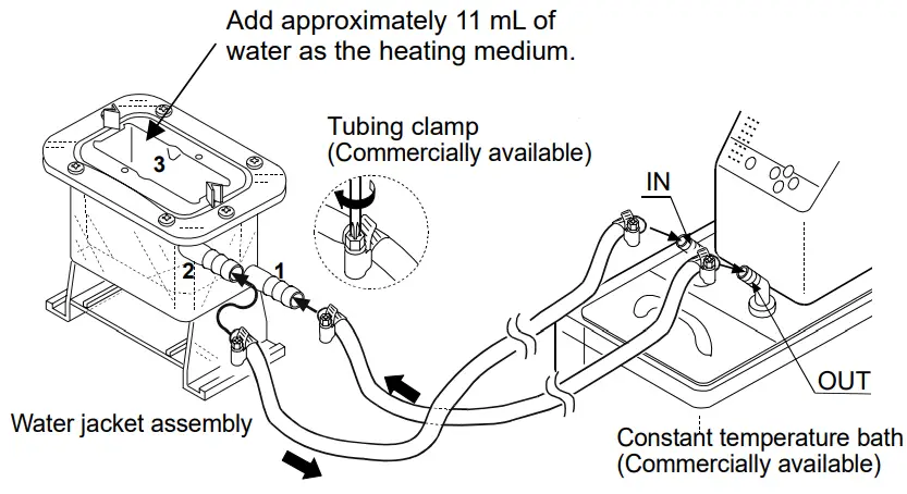
- Using silicone tubes with an inside diameter of 8 mm, make a connection between the “OUT” connector of the bath and the lower nozzle of the water jacket indicated as 1 in the illustration, and then, between the “IN” connector and the upper nozzle indicated as 2.

- Pour the heating medium into the water jacket indicated as 3. An appropriate sample amount is approximately 11 Mr.
The heating medium conducts the heat of the water jacket to the sample cup.
Note: When the levels of the sample surface and the heating medium surface are the same and hard to distinguish the positioning of the sensor plates, change the amount of the heating medium. - Insert the small sample cup into the water jacket indicated as 3.
When the specific gravity of the sample liquid is small and the small sample cup floats, secure lightly the front side of the cup to the water jacket using the screw provided. Use the small sample cup cover for volatile samples.
If the handles of the sample cup holder or the small sample cup interfere with the measurement, they can be removed.
Apply force in the up and down directions slowly as shown in the illustration, to break the handle off.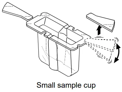
6-3. How to Use
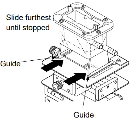
- Attach the water jacket on the table along the guides. Make sure that the water jacket is slid furthest along the guides until stopped.

- When the water jacket is used, be sure to raise or remove the protector.

- Use much care so that the sensor plates and the temperature sensor do not come into contact with the inner wall of the sample. If they are in contact, a measurement error may occur.
- Be sure to adjust the sample surface to the center of the narrow part of the sensor plates.

6-4. Measuring the Absolute Value of Viscosity Using the Small Sample Cup
The RV-10000 has been calibrated using the accessory sample cup (45 mL) when shipped. The distance between the inner wall and the sensor plates when the accessory sample cup is used, differs from the distance when the small sample cup (10 mL) is used. This causes a difference in the sensor plate’s detection capability, thus causing a difference in the viscosity measured.
Therefore, to measure the absolute value of viscosity using the small sample cup (10 mL), it is recommended that calibration be performed using a fluid with a known viscosity value which is close to the sample viscosity. (Refer to “7. VISCOSITY CALIBRATION” of the rheometer instruction manual.)
6-5. Maintenance
Clean the sample cup as necessary. If cleaning is not sufficient, a measurement error may occur due to contamination.
6-6. Specifications
Operating temperature: 0°C to 100°C
Circulation nozzle outside diameter: 10.5 mm
Recommended hose: Silicone tube with an inside diameter of 8 mm
When a stirrer is attached at the bottom of the water jacket, the sample viscosity can be measured while the sample is being stirred. The maximum viscosity value which can be measured is 1000 mPa×s.
Stirrer: VARIOMAG MICRO manufactured by H+P Labor Technik AG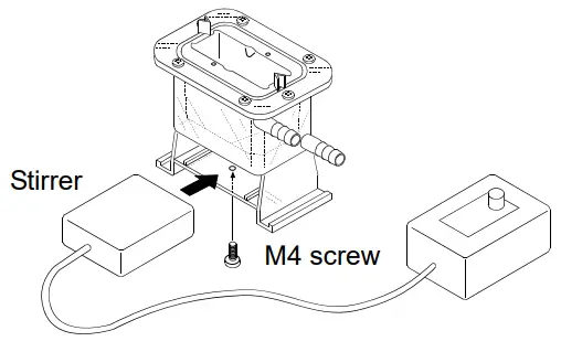
Note
- Use a rotator with a size of 6 mm (length) x 4 mm (diameter).
- Attach the stirrer to the bottom of the water jacket, using an M4 screw from below.
- When the rotator is used, make sure that the rotator will not touch the temperature sensor or the sensor plates. If it does, increase the sample amount so that the rotator will be farther away from the sensor plates.
- Use the stirrer with a revolution speed which will not cause ripples in the sample surface.
VISCOSITY CALIBRATION
- Viscosity calibration is to correct the viscosity value.
- Calibration methods are one-point calibration and two-point calibration using desired standard viscosity fluids. It is also possible to carry out simplified calibration using purified water.
- It is recommended that calibration be performed using a fluid with a known viscosity value which is close to the sample viscosity.
When the measuring range is great, perform two-point calibration. Two-point calibration requires two standard viscosity fluids (high viscosity and low viscosity) that are appropriate for the measuring range. - When measuring the viscosity near 1 mPa×s, simplified calibration using purified water, which is a one-key operation, is available. The RV-10000 has a built-in function to perform an automatic temperature compensation on the viscosity value, based on the temperature of the purified water used.
- In one-point and two-point calibration, the viscosity of a fluid with a known value, such as a standard viscosity fluid, is measured, displayed, corrected digitally and saved in memory.
- To obtain the absolute viscosity value precisely, use the correction value as described in “4-4- 2 At Calibration”.
- If the wrong calibration data such as a correction value have been entered, the rheometer condition can be restored. For details, refer to “Initialization (Cllr)” of the function setting.
7-1 Notes on Viscosity Calibration
- Pay close attention to the liquid temperature at calibration. Be sure to enter the temperature corrected viscosity value of the liquid at calibration. Even when using a standard viscosity fluid, temperature change near room temperature causes viscosity change (if increasing the temperature, the viscosity value decreases about 2 to 10 percent per degree Celsius). And even when using purified water, temperature change similarly causes viscosity decrease of about 2 percent per degree Celsius.
- The temperature of the standard viscosity fluid must be the same as the temperature of the sensor plates and the temperature sensor. Allow the displayed temperature to stabilize before calibration.
- Be sure to adjust the sample surface to the center of the narrow part of the sensor plates. Otherwise, a measurement error may occur.
- In the calibration mode, the unit of viscosity is mPa×s. The unit of temperature is fixed to °C.
- Influence caused by the sample cup
The rheometers have been calibrated with the following cups when shipped. When using another cup, use that cup to measure viscosity only after calibrating with it.
Note
The rheometer has been calibrated with the protector attached when shipped. Please note that the value, obtained when the rheometer is calibrated without the protector, may be different from that upon shipment. - If purified water (such as pressurized tap water) is used for simplified calibration, or the water temperature is different from the ambient temperature, bubbles may accumulate on the sensor plates and cause a measurement error. Remove any accumulated bubbles before calibration.
- If the measured viscosity of the purified water is 3.00 mPa×s or greater, it is contaminated and simplified calibration can not be performed using it. Replace the water.
7-2 Calibration Procedure
Note
As to the correction value used for one-point calibration and two-point calibration, enter the product of the absolute viscosity value and the density of the standard viscosity fluid. For details, refer to “4-4-2 At Calibration”.
After calibration, check the values, comparing the product described above with the displayed value.
Example 1: To calibrate the rheometer using a standard viscosity fluid:
Using the calculation sheet, calculate the value used for calibration.
(1) Check the kinetic viscosity and the viscosity at the temperature when the calibration is performed.
Here, 1011 mm2/s for the kinetic viscosity and 889 mPa×s for the viscosity at 20°C as an example.
(2) Substitute the values above to obtain the value for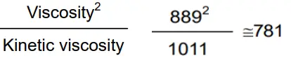
781 mPa×s is obtained as a correction value used for calibration.
Example 2: To calibrate using a standard viscosity fluid with known values of viscosity and density.
In this example, a standard viscosity fluid with a viscosity of 889 mPa×s at 20°C is used.
- Check the viscosity value and the density of the standard viscosity fluid at the temperature when the calibration is performed.. Here, 889 mPa×s for the viscosity and 0.878 for the density at 20°C as an example.
- Substitute the values above to obtain the value for Viscosity . Density. 889 x 0.878 ≈ 781 781 mPa×s is obtained as a correction value used for calibration.
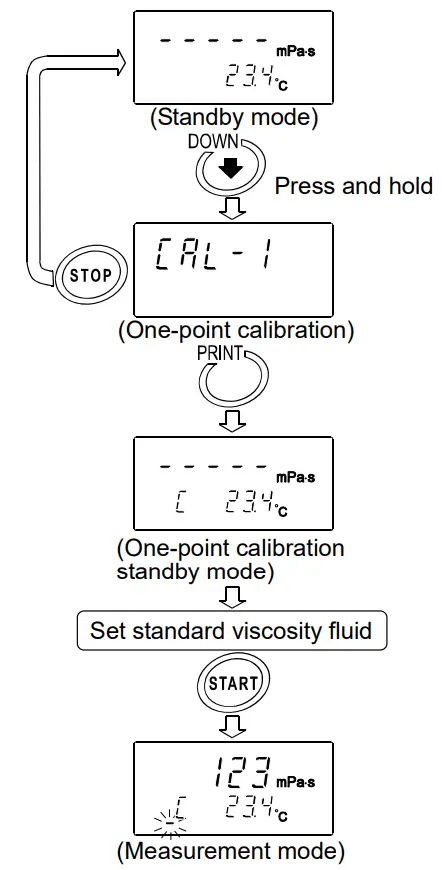
7-2-1 One-point Calibration
- In the standby mode, press and hold the key to enter the calibration mode. ”
 ” appears.
 - Select one-point calibration (
 ) PRINT key to confirm. and press the The standby mode of the one- calibration mode appears. Use the key to switch between the calibration modes, one-point calibration () or two-point calibration (
 ).
).
* Press the calibration STOP key to exit the mode. The display returns to the standby mode. - Place the standard viscosity fluid in the sample cup. Press the START key to start a measurement.
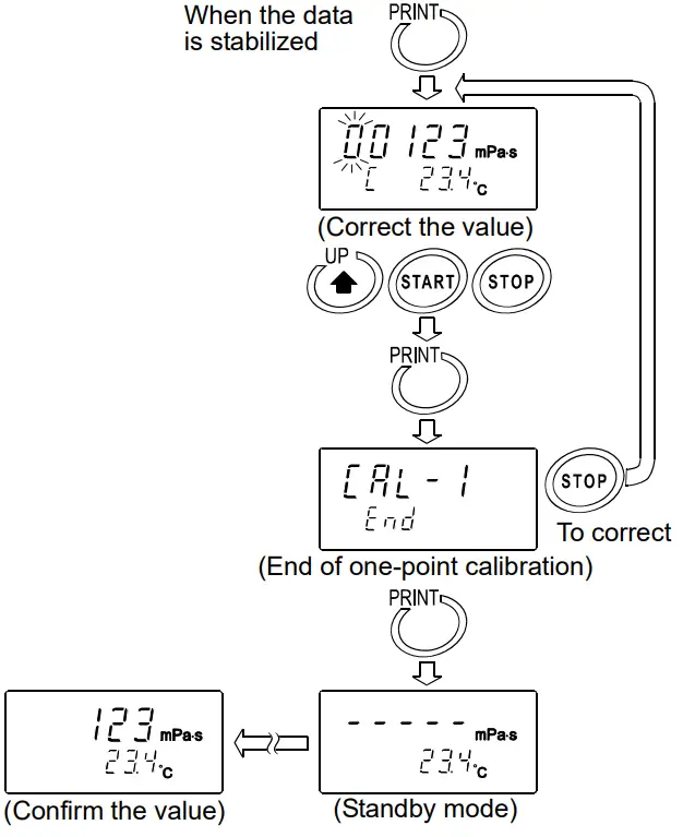
- After the measurement, wait for the display to become stable and press the PRINT key. The measurement value blinks and is ready to be corrected.

- Correct the value using the following keys: key Switches the blinking digits. START key Changes the setting of a blinking digit. STOP key Moves the decimal point.
- Press the PRINT key to confirm the correction value.
- To exit the calibration mode:
With ” ” being displayed, press the PRINT key again to return to the standby mode. To correct the value:
With ” ” being displayed, press the STOP key and correct the value.
- Measure the viscosity of the standard viscosity fluid used. Confirm that the rheometer displays the similar value as the entered correction value.
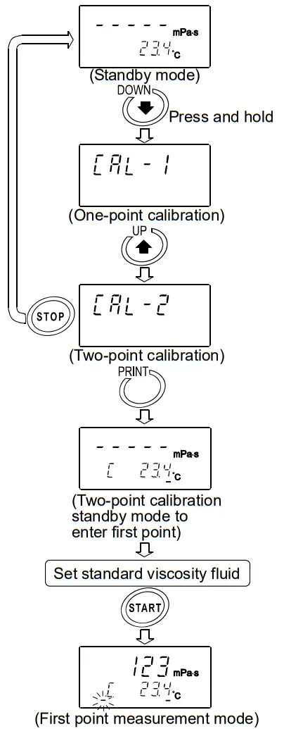
7-2-2 Two-point Calibration
- In the standby mode, press and hold the key to enter the calibration mode. “” appears.
- Select two-point calibration () PRINT key to confirm. and press the The standby mode of the two- calibration mode appears. Use the (One-point calibration) key to switch between the calibration modes, one-point calibration () or two-point calibration ().
* Press the calibration STOP key to exit the mode. The display returns to the standby mode.
- Press the PRINT key to put the display in the standby mode. In two-point calibration mode, the calibration mode ID indicator (-) appears below the temperature display.
- Place the standard viscosity fluid in the sample cup. Press the START key to start the measurement of the first point.
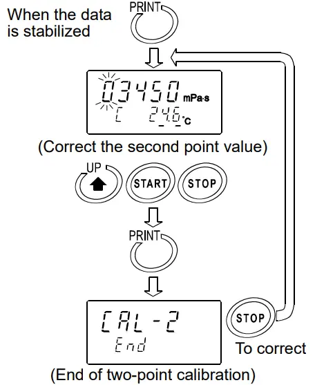
- After the measurement, wait for the display to become stable and press the PRINT key.
The measurement value blinks and is ready to be corrected.
- Correct the value using the following keys: key Switches the blinking digits.
START key Changes the setting of a blinking digit.
STOP key Moves the decimal point. - Press the PRINT key to confirm the correction value.
- To correct the value:
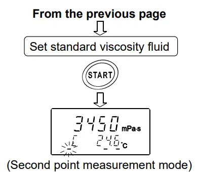
In the calibration standby mode to enter the second point, press the STOP key and correct the value. - When the measurement of the first point has completed, clean the sensor plates, temperature sensor and protector and prepare the second standard viscosity fluid.
- Place the second standard viscosity fluid in the sample cup. Press the START key to start the measurement of the second point.

- After the measurement, wait for the display to become stable and press the PRINT key.
The measurement value blinks and is ready to be corrected. - Correct the value using the following keys: key Switches the blinking digits.
START key Changes the setting of a blinking digit.
STOP key Moves the decimal point.
- Press the PRINT key to confirm the correction value.
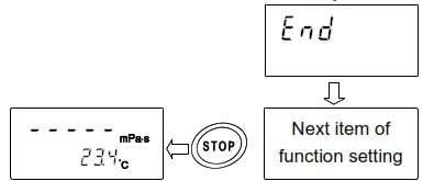
- To exit the calibration mode:
With ” end ” being displayed, press the PRINT key again. The calibration data is saved and the display returns to the standby mode.
To correct the value:
With ” end ” being displayed, press the STOP key and correct the value.
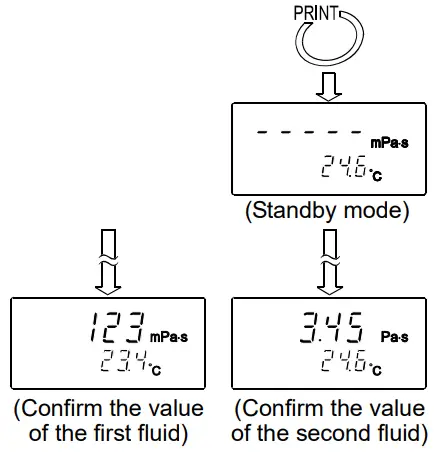
- Measure the viscosity of the two standard viscosity fluids used. Confirm that the rheometer displays the similar value as the entered correction value for each fluid.

7-2-3 Simplified Calibration Using Purified Water
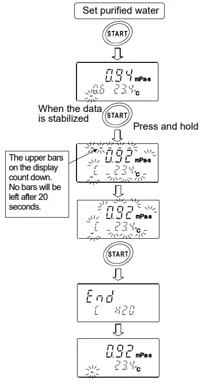
- Place the purified water in the sample cup.
- Press the START the purified water. key to measure Confirm that the viscosity and temperature values are stabilized.
- Press and hold the START key.
The theoretical viscosity value (Viscosity x Density) of the purified water at the measuring temperature is displayed and all the displays blink.
To cancel the operation, press the key. The display returns to STOP the status before calibration. - Press the START key again to perform calibration.
When calibration is completed, ”” is displayed. Then, the viscosity returns to the measuring status.
Reference data: Theoretical viscosity value (Viscosity x Density) of the purified water at various temperatures
| Temperature (°C) | Viscosity ´ Density (mPa×s) |
| 10.0 | 1.31 |
| 11.0 | 1.27 |
| 12.0 | 1.24 |
| 13.0 | 1.20 |
| 14.0 | 1.17 |
| 15.0 | 1.14 |
| 16.0 | 1.11 |
| 17.0 | 1.08 |
| 18.0 | 1.05 |
| 19.0 | 1.03 |
| 20.0 | 1.00 |
| 21.0 | 0.98 |
| 22.0 | 0.95 |
| 23.0 | 0.93 |
| 24.0 | 0.91 |
| 25.0 | 0.89 |
| 26.0 | 0.87 |
| 27.0 | 0.85 |
| 28.0 | 0.83 |
| 29.0 | 0.81 |
| 30.0 | 0.79 |
Note
- When tap water is poured into the sample cup directly and is measured, bubbles are generated on the sensor plates due to the difference in pressure and temperature and the viscosity may increase gradually. Pressurized tap water generates bubbles easily. Therefore, use distilled or purified water that is not pressurized. Leave the sensor plates and sample in the same environment to acclimatize before measuring, to decrease temperatures fluctuations.
- In a measurement that takes a long time, the sample viscosity may increase due to water contamination. Perform a periodic check on water quality.
FUNCTION SETTING
The rheometer, by selecting functions to be used in the function setting, can specify the performance appropriate to the usage.
Each function is assigned parameters. The performance of a function is specified by changing the parameter.
The parameters saved, even if the power is turned off, are maintained in non-volatile memory.
8-1 Operation
The operational procedure of the function setting is as follows:
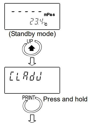
- In the standby mode, press and hold the key for at least 2 seconds to enter the function setting mode.
- Press the key to select a function item.
- Press the PRINT key to confirm the function item. The changeable digit blinks.
- Press the START key or key to change the blinking digit.
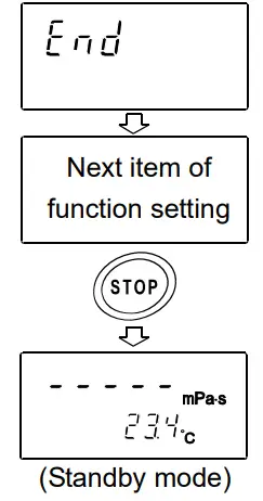
START key Increases the value of the blinking digit. When the value reaches the upper limit of the setting range, the minimum value appears again. key Decreases the value of the blinking digit. When the value reaches the lower limit of the setting range, the maximum value appears again. - To save the new setting, press the PRINK key. After ” end “, the next item is displayed.
To cancel the new setting, press the STOP key. The next item is displayed. - To change other settings, repeat the procedure starting at step 2.
- To exit the function setting mode, press the STOP key. The rheometer returns to the standby mode.
Note
The operational procedures for setting the date and time ![]() , ID number
, ID number ![]() and initialization
and initialization ![]() are not the same as the procedure described above. Refer to “8-3 Description of Items”.
are not the same as the procedure described above. Refer to “8-3 Description of Items”.
“Date/Time” pages 44-46
“Device ID Number” pages 42
Example of the function setting procedure
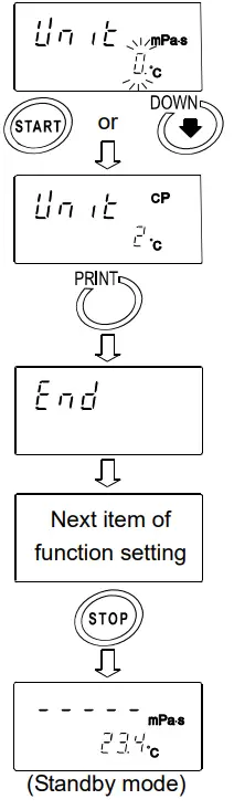
To change the setting of “Unit upon power-on ![]() to the viscosity: cpm (Centipoise) and the temperature: °C (Celsius).
to the viscosity: cpm (Centipoise) and the temperature: °C (Celsius).
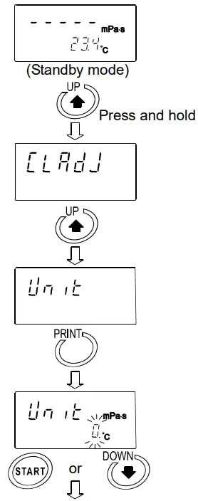
- In the standby mode, press and hold the key to enter the function setting mode. ”
 ” appears.
- Press thekey to select ”
 “.
“. - Press the PRINT key to confirm the item.
(The decimal point illuminates when the setting currently saved is displayed.) - Press the START key or the unit to be used. key to select
(In this example, ” 2 ” is selected. Viscosity: cpm, Temperature: °C) - Press the PRINT key to save the setting. After ” “, the next item is displayed.

- Press the STOP key to return to the standby mode.
8-2 Details of the Function Items
| Function item | Parameter | Description | ||||||||||
| Sets the order of the date (YMD,MDY,DMY) and the date/time. | ||||||||||||
| Follows the viscosity changes quickly. (Prone to vibration) | ||||||||||||
| • | ||||||||||||
| Follows the viscosity changes slowly. | (Stable values) | |||||||||||
Unit upon power-on | Viscosity | mPa×s |
Temper- ature | °C | ||||||||
| Pa×s | ||||||||||||
| cpm | ||||||||||||
| P | ||||||||||||
| mPa×s | °F | |||||||||||
| Pa×s | ||||||||||||
| cpm | ||||||||||||
| P | ||||||||||||
Decimal point | Dot | With “Comma” selected, the separator for CSV format will be “;” (semicolon). | ||||||||||
| Comma | ||||||||||||
Data output mode | Key mode | Press the | key to output data. | |||||||||
| 1 | Auto print mode | Outputs automatically when the STOP key ends the measurement. | ||||||||||
| Stream mode | Continuous output during measurement. Outputs the viscosity only when D.P. format is selected. | |||||||||||
Data output format | A&D standard format | For AD-8121B MODES 1&2 | ||||||||||
| 1 | · | D.P. format | For AD-8121B MODE 3 | |||||||||
| CSV format | For a personal computer | |||||||||||
| Viscous format | For graphing program Viscous | |||||||||||
Measurement elapsed time output | No output | Available only for D.P. format | ||||||||||
| 1 | · | Output | ||||||||||
| No output | Available only for D.P. and CSV formats | |||||||||||
| 1 | • | Output | ||||||||||
| No output | ||||||||||||
| Other output | 1 | Outputs remarks. | Available only for D.P. format | |||||||||
| • | Outputs remarks, Device ID information and signature. | |||||||||||
| Outputs ID number. | Available only for CSV format | |||||||||||
Pause at data output | No pause | |||||||||||
| 1 | • | Pause (Approx. 2 seconds) | ||||||||||
| Usually use this parameter. | ||||||||||||
| | | ||||||||||||
ID number output | Sets the ID number output | By setting | ||||||||||
| Restores the function settings and calibration data to the factory setting. | ||||||||||||
• Factory setting
8-3 Description of Items
Condition (![]() )
)
The stability of the viscosity measurement results can be adjusted, taking ambient conditions such as vibration into consideration.
| Parameter | Settings | Description |
| Follows the viscosity changes quickly. (Prone to vibration) | When the viscosity value is unstable due to external vibration, set a greater parameter. To measure while following the rapid changes in viscosity, set a smaller parameter. With a smaller setting, the measurement is prone to external vibration. Consider the ambient conditions of the installation site. | |
| ↔ | ||
| Follows the viscosity changes slowly. (Stable values) |
Unit Upon Power-on (![]() )
)
The units of viscosity and temperature displayed when the power is turned on are specified.
| Parameter | Settings | Description | |||
| | Viscosity | mPa×s (Millipascal second) | Temper- ature | °C (Celsius) | With |
| Pa×s (Pascal second) | |||||
| cP (Centipoise) | |||||
| P (Poise) | |||||
| mPa×s (Millipascal second) | °F (Fahrenheit) | ||||
| Pa×s (Pascal second) | |||||
| cP (Centipoise) | |||||
| P(Poise) | |||||
*1 For the viscosity over 1000mPa.s, the unit is fixed to Pa.s. For the viscosity over 1000cP, the unit is fixed to P.
Decimal Point (![]() )
)
| Parameter | Settings | Description |
| | Dot “.” | The decimal point format for the displayed measurement data and the decimal point code for measurement data output via RS-232C are specified. With “Comma” selected, the separator for CSV format and Rs Viscos format will be “;” (semicolon). |
| Comma “,” |
Data Output Mode (![]() )
)
The condition to output the measurement data via RS-232C is set.
| Parameter | Settings | Description |
| | Key mode | During measurement or in the data hold mode, pressing the PRINT key outputs the current measurement values. |
| Auto print mode | The measurement values are output automatically when the STOP key ends the measurement. Pressing the PRINT key outputs the measurement values again. | |
| Stream mode | The measurement values are output continuously during measurement. When D.P. format is selected in “Output format ( When this mode is selected, the data hold mode using the HOLD key is not available. |
Data Output Format ( ![]() )
)
The output format appropriate for the device connected to RS-232C can be selected.
| Parameter | Settings | Description |
| A&D standard format | Used with the printer MODE 1 or MODE 2 when the optional compact printer AD-8121B is connected. Only the viscosity value is output. | |
| 1 · | D.P. format | Used with the printer MODE 3 when the optional compact printer AD-8121B is connected. With |
| 2 | CSV format | Appropriate when a personal computer is used to collect data. Measurement values are output in comma separated format. With “ When a comma is selected as the decimal point by “ The viscosity value and the temperature are output using the internal resolution. *2 |
| 3 | Viscous format | Used with the graphing program Viscous. When a measurement is started using Viscous, the rheometer automatically selects this format. The viscosity value and the temperature are output using the internal resolution.*2 |
*2 The relation between the measuring unit and the internal resolution is as follows:
| Viscosity | Temperature | |||||
| mPa×s | Pa・s | cP | P | °C | °F | |
| Internal resolution | 0.01 | 0.0001 | 0.01 | 0.0001 | 0.01 | 0.01 |
| – | 0.01 | – | 0.1 | |||
Measurement Elapsed Time Output (![]() )
)
| Parameter | Settings | Description |
| No output | With D.P. format selected, whether or not to add the measurement elapsed time (the time elapsed from a measurement start) to the measurement data can be selected. For examples of output format, refer to “8-4 Data Output Format Examples”. | |
| Output |
Date/time Output (![]() )
)
| Parameter | Settings | Description |
| No output | With D.P. format or CSV format selected, whether or not to add the date and time to the measurement data can be selected. For examples of output format, refer to “8-4 Data Output Format Examples”. | |
| Output |
Other Output (![]() )
)
| Parameter | Settings | Description |
| No output | ||
| Outputs remarks. | With D.P. format selected, whether or not to add remarks, Device ID information or signature to the measurement data can be selected. For examples of output format, refer to “8-4 Data Output Format Examples”. | |
| Outputs remarks, Device ID information and signature. | ||
| Outputs ID number. | With CSV format selected, whether or not to add ID number to the measurement data can be selected. For examples of output format, refer to “8-4 Data Output Format Examples”. |
Pause at Data Output (![]() )
)
| Parameter | Settings | Description |
| No pause | Whether or not to take a pause of two seconds each time one line is output can be selected, when the data are output via RS-232C. When MODE 3 of the optional compact printer AD-8121B is used, select “ | |
| Pause (Approx. 2 seconds) |
Device ID Number (id)
- The ID number is used to identify the rheometer.
- Whether or not to add the ID number to the measurement data can be selected by “
 ” of the function setting.
 - The ID number is six characters long. The following characters are available for the ID number.
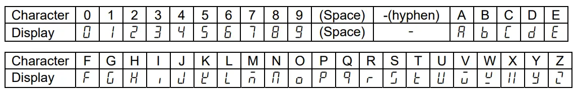
For examples of output format, refer to “8-4 Data Output Format Examples”.
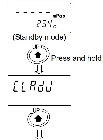
Setting the ID number
- In the standby mode, press and hold the key to enter the function setting mode. ”
 ” appears.
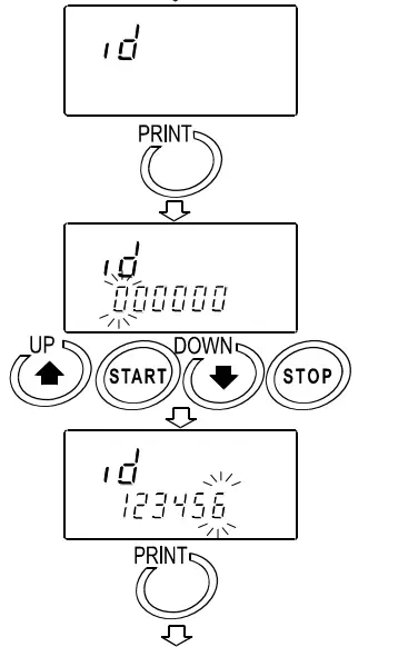
- Press thekey to select ” id “.
- Press the PRINT key to enter the ID number setting mode.

- Set the ID number using the following keys: key Switches the blinking digits.
START key Increases the value of the blinking digit by one. key Decreases the value of the blinking digit by one.
STOP key Cancel the operation
- Press the PRINT key to save the setting. After ” “, the next item is displayed.
- Press the STOP key to return to the standby mode.
Initialization (![]() )
)
Restores the following data to the default setting.
- Function setting (Setting of “
 ” is not returned by this operation)
 - Calibration data
After initialization, check the viscosity value and perform calibration as necessary. (Refer to “7. VISCOSITY CALIBRATION”).
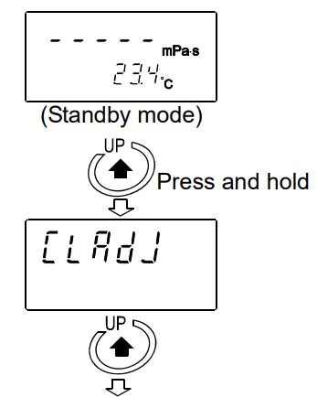
- In the standby mode, press and hold the key to enter the function setting mode. ” ” appears.

- Press the key to select “
 “.
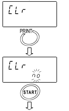
“. - Press the PRINT key to display ”
 “.
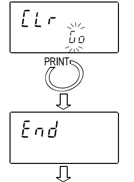
“. - Press the START key to select ”
 “.
“.
- Press the PRINT key to execute initialization. After ” “, the next item is displayed. Initialization has completed.

- Press the STOP key to return to the standby mode.

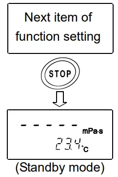
Date/Time (![]() )
)
- The upper two digits of the year are not displayed. For example, the year 2007 is displayed as “07”.
- The time is set using the 24-hour system.
- Do not enter a non-existing date and time.
Set the order of the date, the date and time as follows:
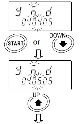
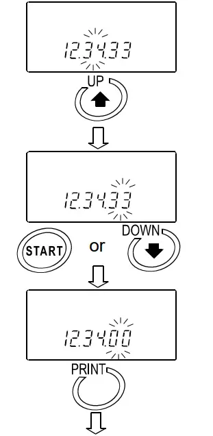
(Example: To change April 5, 2003, 11:22:33 to June 8, 2004, 12:34:00)
- In the standby mode, press and hold the key to enter the function setting mode. ” ” appears.

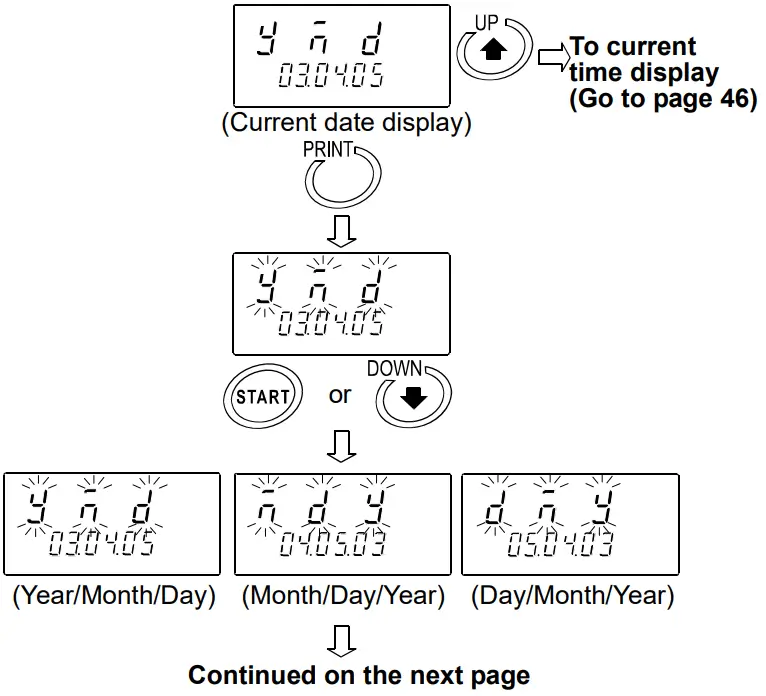
- Press the PRINT key to display the current date. When the date is not to be changed, press thekey to display the current time.
 Changing the order of the date
 - Press the PRINT key. ”
 ” (Year), ”
  ” (Month) and ”
  ” (Day) blink.
 - 4 Press the START key or key to change the order of displaying the date.
Changing the date
The date is changed in the selected displaying order.
The following is an example when the order of ” ” (Year), ” ” (Month) and ” ” (Day) is selected.
- Press the key to select the setting value of ” ” (Year). (Example:03)
- Press the START key or key to change the year. (Example:03→04)
START key Increases the value of the blinking digit by one. key Decreases the value of the blinking digit by one.
- Press thekey to select the setting value of “ ” (Month). (Example:04)
- Press the START key or key to change the month. (Example:04→06)

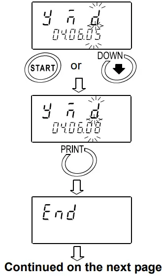
- Press the key to select the setting value of ” ” (Day). (Example:05)
- Press the START key or key to change the day. (Example:05→08)
- Press the PRINT key to save the date.
After ” “, the current time is displayed.
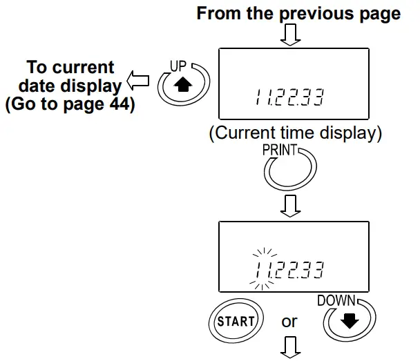
Changing the time - The current time is displayed. Press the key to display the current date.
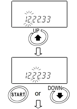
- Press the PRINT key to select the setting value of the hour. (Example:11)

- Press the START key or key to change the hour. (Example:11→12)
- Press thekey to select the setting value of the minute. (Example:22)

- Press the START key or key to change the minute. (Example:22→34)
- Press the key to select the setting value of the second. (Example:33)

- Press the START key or key to change the second. (Example:33→00)
- Press the PRINT key to save the time. After ” “, the next item is displayed.

- 20 Press the STOP key to return to the standby mode.
 Changing the order of the date
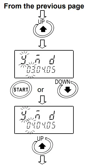
8-4 Data Output Format Examples
8-4-1 A&D Standard Format
Used with the printer MODE 3 when the optional compact printer AD-8121B is connected. Only the viscosity value is output.
Output format example
| Viscosity unit | Display | Output format | Remarks |
| mPa×s | L mPa×s | OL,-99999999mPs | Below measuring range error |
| 0.30mPa・s | ST,+00000.30mPs | ||
| 10.0 mPa×s | ST,+00010.00mPs | The digit of 0.01mPa×s is always zero. | |
| 100 mPa×s | ST,+00100.00mPs | The digits of 0.01mPa×s and 0.1mPa×s are always zero. | |
| 1.00 Pa・s | ST,+01000.00mPs | For 1000mPa×s or greater, the displayed unit is Pa×s, but the output unit remains mPa×s. The digits of 0.01mPa×s, 0.1mPa×s and 1mPa×s are always zero. | |
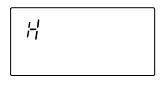
| H Pa・s | OL,+99999999mPs | Above measuring range error | |
| Pa・s | L Pa・s | OL,-99999999Pas | Below measuring range error |
| 0.0003 Pa・s | ST,+000.0003Pas | ||
| 0.0100 Pa・s | ST,+000.0100Pas | ||
| 0.100 Pa・s | ST,+000.1000Pas | The digit of 0.0001Pa×s is always zero. | |
| 1.00 Pa・s | ST,+001.0000Pas | The digits of 0.0001Pa×s and 0.001Pa×s are always zero. | |
| H Pa・s | OL,+99999999Pas | Above measuring range error | |
| cP | L cP | OL,-99999999 | Below measuring range error |
| 0.30 cP | ST,+00000.30 | ||
| 10.0 cP | ST,+00010.00 | The digit of 0.01cP is always zero. | |
| 100 cP | ST,+00100.00 | The digits of 0.01cP and 0.1cP are always zero. | |
| 10.0 P | ST,+01000.00 | For 1000 cP or greater, the displayed unit is P, but the output unit remains cP The digits of 0.01cP, 0.1cP and 1cP are always zero. | |
| H P | OL,+99999999 | Above measuring range error | |
| P | L P | OL,-99999999 | Below measuring range error |
| 0.0030 P | ST,+000.0030 | ||
| 0.100 P | ST,+000.1000 | The digit of 0.0001P is always zero. | |
| 1.00 P | ST,+001.0000 | The digits of 0.0001P and 0.001P are always zero. | |
| 10.0 P | ST,+010.0000 | The digits of 0.0001P, 0.001P and 0.01P are always zero. | |
| H P | OL,+99999999 | Above measuring range error |
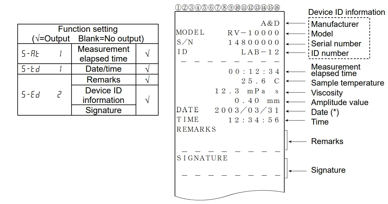
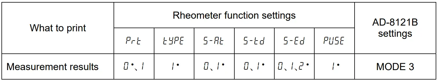
8-4-2 D.P. Format
Used with the printer MODE 3 when the optional compact printer AD-8121B is connected.
With ![]() selected for “Data output mode (
selected for “Data output mode (![]() ) “, output contents can be selected by the settings of
) “, output contents can be selected by the settings of ![]() .
.
With “![]() ” selected for “Data output mode (
” selected for “Data output mode (![]() )”, only the viscosity value is output The following shows printing examples.
)”, only the viscosity value is output The following shows printing examples.
Printing format example (1)
Printing format example (2)
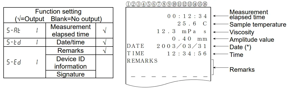
Printing format example (3)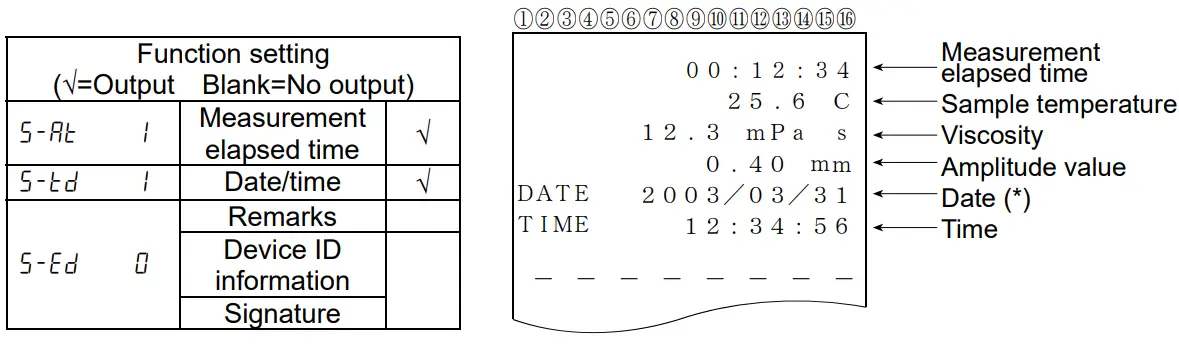
(*) The displaying order of the date (YMD/DMY/MDY) depends on the setting of “Date/Time (![]() )”.
)”.
Printing format example (4)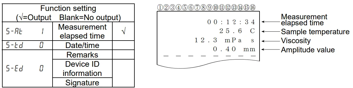
Printing format example (5)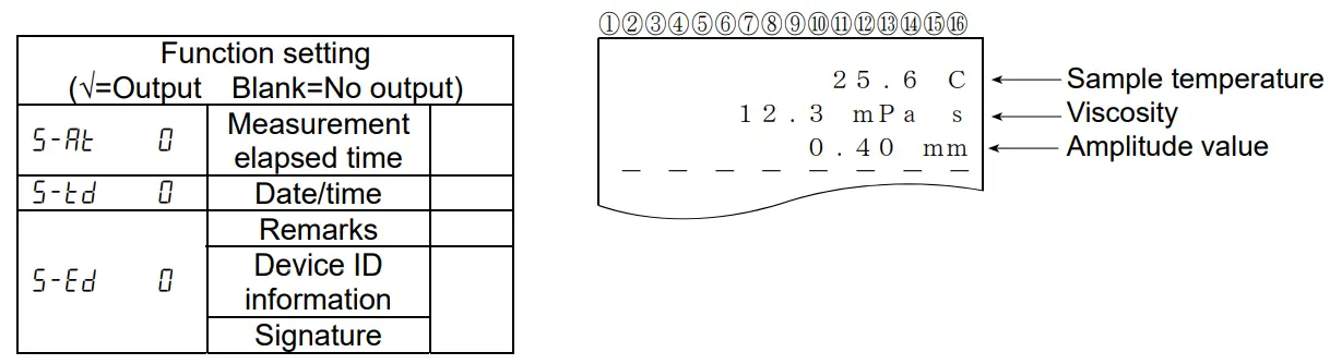
8-4-3 CSV Format
Appropriate when a personal computer is used to collect data. Measurement values are output in comma separated format.
With “![]() ” setting, the date and time can be added to the measurement data.
” setting, the date and time can be added to the measurement data.
When a comma is selected as the decimal point by “![]() “, a semicolon “;” is used as a data separator.
“, a semicolon “;” is used as a data separator.
With CSV format selected, the viscosity value and the temperature are output using the internal resolution.
The relation between the measuring unit and the internal resolution is as follows:
| Viscosity | Temperature | Amplitude value | |||||
| mPa×s | Pa・s | cP | P | °C | °F | mm | |
| Internal resolution | 0.01 | 0.0001 | 0.01 | 0.0001 | 0.01 | 0.01 | 0.01 |
| - | 0.01 | - | 0.1 | ||||
Output format example (1) With ID number, date and time added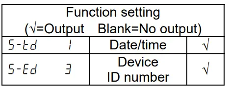
Outputs in the order of ID number, date, time, temperature, temperature unit, viscosity and viscosity unit.
The output data are 52 characters long excluding the terminator.
Output format example
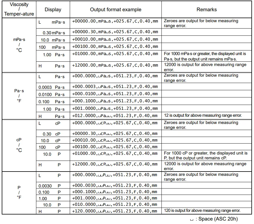
Output format example (2) With date and time added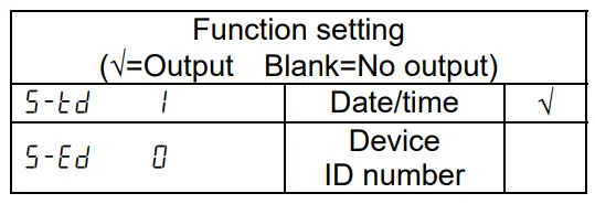 Outputs in the order of date, time, temperature, temperature unit, viscosity and viscosity unit. The output data are 46 characters long excluding the terminator.
Output format example
| Viscosity / Temperature | Display | Output format example |
| mPa×s / °C | 1.23 mPa×s | ,2003/03/19,12:34:56,+025.67,C,+00001.23,mPa s,0.40,mm |
![]() :Space (ASC 20h)
:Space (ASC 20h)
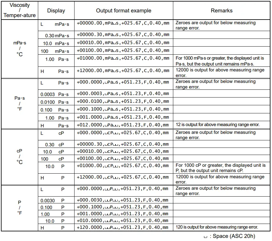
Output format example (3) To output the measured temperature and viscosity only
Outputs in the order of temperature, temperature unit, viscosity and viscosity unit. The output data are 28 characters long excluding the terminator.
Output format example
| Viscosity / Temperature | Display | Output format example |
| mPa×s / °C | 1.23 mPa×s | ,,,+025.67,C,+00001.23,mPa s,0.40,mm |
![]() :Space (ASC 20h)
:Space (ASC 20h)
8-4-4 Viscous Format
Used with the graphing program Viscous. Measurement data are output in comma separated format.
When a comma is selected as the decimal point by “![]() “, a semicolon “;” is used as a data separator.
“, a semicolon “;” is used as a data separator.
When a measurement is started using Viscous, the rheometer automatically selects this format.
Measurement data are output in the order of viscosity, viscosity unit, temperature and temperature unit.
The output data are 25 characters long excluding the terminator
With Viscous format selected, the viscosity value and the temperature are output using the internal resolution.
The relation between the measuring unit and the internal resolution is as follows:
| Viscosity | Temperature | Amplitude value | |||||
| mPa×s | Pa・s | mm | P | °C | °F | mm | |
| Internal resolution | 0.01 | 0.0001 | 0.01 | 0.0001 | 0.01 | 0.01 | 0.01 |
| - | 0.01 | - | 0.1 | ||||
Output format example
CONNECTION TO A PERSONAL COMPUTER
9-1 Introduction
If connecting the RV-10000 to a personal computer using the Windows communication tools Win CT- Viscosity (CD-ROM), the measurement data can be imported into the personal computer.
The graphing program Viscous that is contained in the Windows communication tools Win CT- Viscosity has following features.
– This program can display a graph of the sample viscosity changing in real time. At this time, the sample temperature is imported into the personal computer. Therefore you can easily understand the sample characteristic by displaying a graph of the relation between the temperature and viscosity.
– When measuring at any time, you can compare the sample characteristic by displaying a graph on a graph.
– The measurement data can be saved with the CSV file in the personal computer. The input data can be displayed as a graph again.
– The graph data can be printed with a printer that is connected to the personal computer.
* For an example of a measurement, refer to the sample measurement collection. For details of how to use the examples, refer to “Readme” that is installed in the personal computer after the CD-ROM set up.
9-2 Installation of Win CT-Viscosity
Refer to “\English\ReadMe.txt” on the CD-ROM, to install Win CT-Viscosity in a personal computer.
9-3 Connection to a personal computer
In a case where the personal computer has a COM port
The RV-10000 can connect to a personal computer using the RS-232C cable.
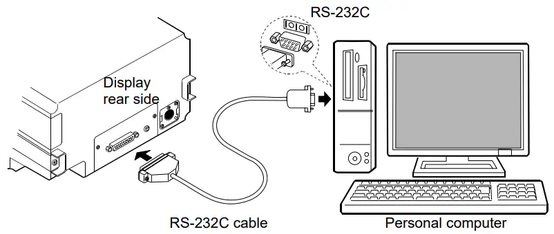
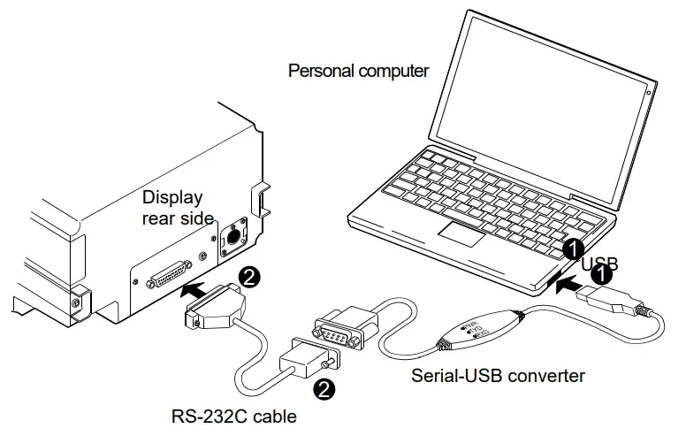
In a case where the personal computer does not have a COM port (Example: notebook type etc)
By using the standard Serial-USB converter provided, a personal computer can increase the number of COM ports available. Therefore, the RV-10000 can connect to a personal computer using the RS- 232C cable.
Setting up
- Connect the Serial-USB converter to the personal computer. Install the driver of the Serial-USB converter in the personal computer (Refer to the instruction manual of the Serial-USB converter.).
- Connect the Serial-USB converter to the RV-10000 by using the RS-232C cable.
9-4 Configuration of the COM port
When connecting the RV-10000 to a personal computer, confirm that the COM port setting match up.
(1) Configuring of the COM port
- Click the START bottom → the“Setting” → the“Control panel”.
- Double-click the“System” .
- Click the“Hardware” Tab, and click the“Device Manager” .
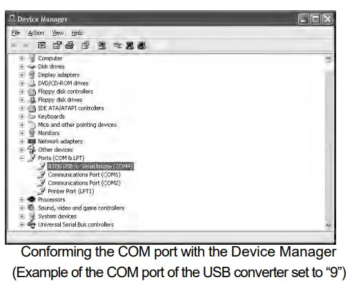
- Double-click the“Port (COM and LPT)” ,confirm the number of the COM port.
When using the USB converter, “ATEN USB to Serial Bridge (CM4)” is displayed.
With this example, the COM port is displayed set to “4”. The COM port of the personal computer is displayed as “Communications Port (COM1)”.
 With this example, The COM port of the personal computer is two. Therefore, the COM port number that is connected to the personal computer directly is displayed as “1” and “2”. When a personal computer has many COM ports, all of the COM ports are displayed sequentially (Example: Communications Port (COM1), Communications Port (COM2)…) Confirm the COM port number by the connecting position of the COM port.
(2) Setting of the COM port (Example: graphing software“RsVisco”)
1 Click the START bottom → the“Program” → the“A&D Win CT-Viscosity” → the “Viscous”.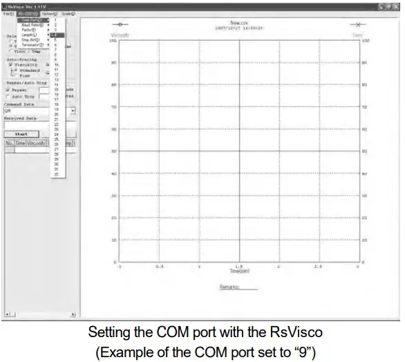
5 With “RS-232C (R)” of menu → the“COM Port (C)”, set the COM port described above “ (1) Configuring of the COM port”
9-5 Controlling the measurement using a personal computer
(In case of the graphing software“RsVisco”)
- Refer to “5. MEASUREMENT”, prepare the measurement.
- Start the graphing software“RsVisco”.
- Confirm that the COM port of the“RsVisco” is set properly.
- Click the START button of the“RsVisco” to start the measurement.
- If you want to finish the measurement, click the START button of the“RsVisco”.
* For details on how to use the software, refer to the file “Readme” that is installed in a personal computer after the CD-ROM set up.
CONNECTION TO A PRINTER
- The rheometer can be connected to the optional compact printer AD-8121B using the standard RS-232C interface and the measurement results can be printed.
- The statistical calculation data of the results and the changes in the viscosity value per a certain time can be printed using the function of the AD-8121B.
- Use the AD-8121B accessory cable to connect the printer to the rheometer.
Setting List
 • Factory setting
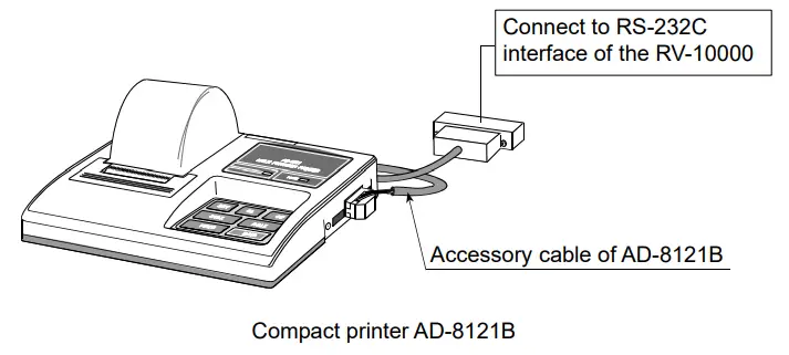
Note
AD-8121B settings
| Mode | AD-8121B DIP switches | Description |
| Mode 1 | 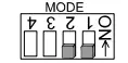 | Prints upon data receipt Standard mode, statistical calculation mode |
| Mode 2 |  | Prints using the AD-8121B DATA key or the AD-8121B built-in timer Standard mode, interval mode, chart mode |
| Mode 3 | 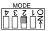 | Prints upon data receipt Dump print mode |
DIP switch 3: Handling unstable data
ON = To print unstable data OFF = Not to print unstable data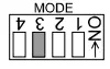
DIP switch 4: Data input specification
ON = Use the current loop OFF = Use the RS-232C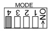
RS-232C SERIAL INTERFACE
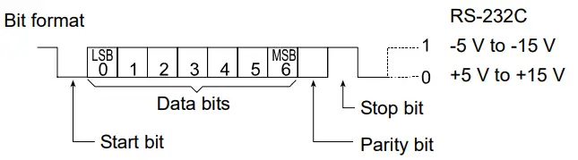
RS-232C Serial Interface
| Transmission system | EIA RS-232C |
| Transmission form | Asynchronous, bi-directional, half duplex |
| Data format | Baud rate 2400 bps |
| Data bits | 7 bits |
| Parity | EVEN |
| Stop bit | 1 bit |
| Code | ASCII |
| Terminator | CR LF (CR: 0Dh, LF: 0Ah) |
 Pin Connections
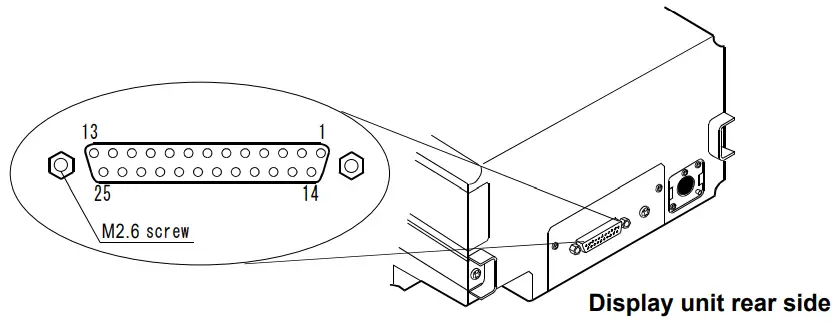
RV-10000 (DCE) | Computer (DTE) | |||
| Pin No. | Signal Name *1 | Description | Direction | Signal Name |
| 1 | FG | Frame ground | – | FG |
| 2 | RXD | Receive data | ← | TXD |
| 3 | TXD | Transmit data | → | RXD |
| 4 | RTS | Ready to send *2 | ← | RTS |
| 5 | CTS | Clear to send *2 | → | CTS |
| 6 | DSR | Data set ready | → | DSR |
| 7 | SG | Signal ground | – | SG |
| 16, 18, 19, 21, 23 | Internal use | Do not connect *3 | ||
| Others | Not used | |||
*1: Signal names of the rheometer side are the same as the DTE side with TXD and RXD reversed.
*2: RTS and CTS flow control are not used. CTS output is HI always.
*3: Normal DOS/V cables do not use these terminals.
COMMAND LIST
The rheometer can be controlled by the following commands from the computer. Add a terminator![]() ( 0Dh、0Ah ) to each command.
( 0Dh、0Ah ) to each command.
| Command | Description |
| Q | Outputs the current data. (This is effective whether not measurement being carried out.) |
| SIR | Outputs data continuously |
| C | Stops data output by SIR command. |
| QM | Outputs the data during measurement. (This is effective only while measurement is being carried out.) |
| START | Same as the START key |
| STOP | Same as the STOP key |
| HOLD | Same as the |
| MODE | Same as the |
| Same as the PRINT key |
TROUBLESHOOTING
The rheometer is a precision instrument. When the operating environment or the operating method is inadequate, correct values can not be obtained. If measurement values do not become stable or they seem to be incorrect, check as described below. If improper performance persists after checking, contact the local A&D dealer for repair.
13-1 When measurement values do not become stable![]() Is the ambient environment free from vibration and drafts?
Is the ambient environment free from vibration and drafts?
- Places such as second or higher floor or near busy highways or rail lines are prone to vibration.
Avoid these places or use an anti-vibration table, AD-1671A. - Reconsider the setting of “Condition (
 ) ” of the function setting.
Set it to “ “.
“. - Avoid direct drafts in the vicinity of the rheometer.
![]() Is there a strong electrical or magnetic noise source such as a motor near the rheometer?
Is there a strong electrical or magnetic noise source such as a motor near the rheometer?
- Install the rheometer away from the electrical or magnetic noise sources
![]() Is the protector or the sensor protective cover in contact with the sensor plates or the temperature sensor?
Is the protector or the sensor protective cover in contact with the sensor plates or the temperature sensor?
- Attach the protector and the sensor protective cover properly so that they do not touch the sensor plates or the temperature sensor.
- Remove the protector, the surface locator plate or the sensor protective cover when necessary.
(1) How to remove the protector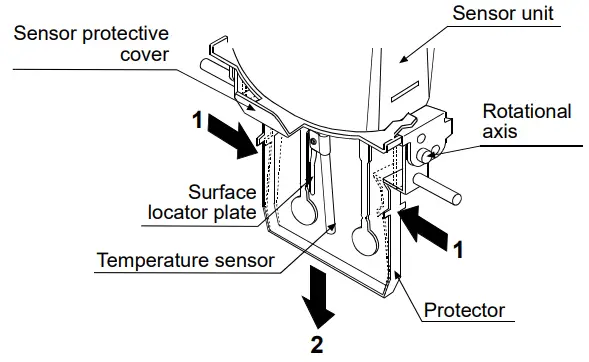
Press the left and right side frames lightly in the direction indicated as 1 to remove the rotational axis. Pull the protector in the direction indicated as 2 to remove.
(2) How to remove and attach the surface locator plate
Removing
Loosen the screw and remove the surface locator plate from the temperature sensor.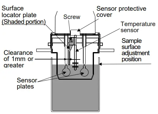
Attaching
Install the surface locator plate as shown in the illustration. Slip the locator plate onto the temperature sensor. Move the plate to the top of the sensor. Adjust the position of the locator plate so that the tip of the locator plate aligns to the center of the narrow part of the sensor plates. Tighten the screw.
Note
When the sensor plate and the surface locator plate are too close, a measurement error may occur due to the liquid surface tension. Therefore, secure a clearance of at least 1 mm between the sensor plate and the surface locator plate. Maintain the clearance by rotating the surface locator plate when necessary.
(3) How to remove the sensor protective cover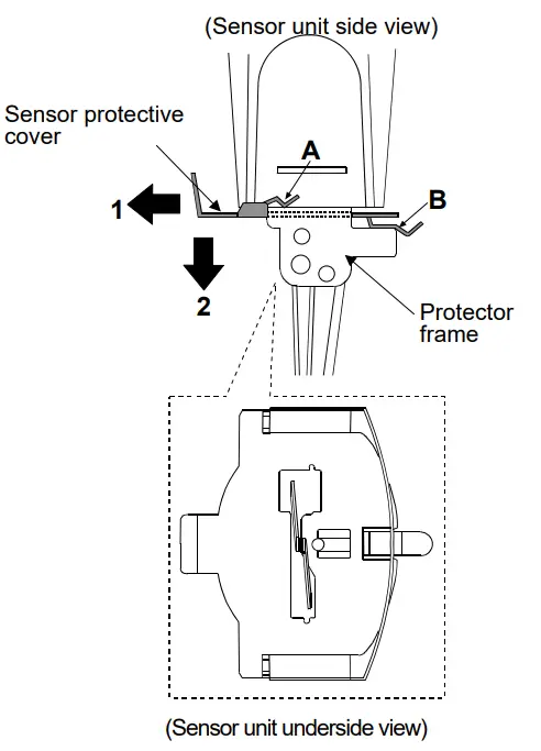
Remove the protector and the surface locator plate.
Pull the sensor protective cover in the direction indicated as 1 to release the portions A (two) and B from Sensor protective cover 1 the protector frame.
Pull the sensor protective cover in the direction indicated as 2 to remove.
Note
When removing the sensor protective cover, it may touch the sensor plates and the temperature sensor. Use much care not to damage them.
13-2 When measurement values are not correct![]() Has the sample surface been adjusted to the center of the narrow part of the sensor plates?
Has the sample surface been adjusted to the center of the narrow part of the sensor plates?
• Adjust the table height by turning the knob so that the center of the narrow part of the sensor plates is on the sample surface.![]() Are the positions of the left and right sensor plates in the sample surface the same?
Are the positions of the left and right sensor plates in the sample surface the same?
• If not the same, level the rheometer using the leveling feet so that the liquid surface will be leveled.![]() Are the sensor plates clean?
Are the sensor plates clean?
• Remove any residual sample material from the sensor plates using alcohol.
• When any residual sample material is on the portion of the sensor plates above the sample surface, changes in the mass cause the vibration frequency to shift, which will result in a measurement error.![]() Are the sensor plates bent?
Are the sensor plates bent?
• If bent, contact the local A&D dealer for repair.![]() Is the protector properly attached to the rheometer.
Is the protector properly attached to the rheometer.![]() Does the sample generate bubbles because of the differences in the sample temperature and the ambient temperature and do the bubbles stick to the sensor plates?
Does the sample generate bubbles because of the differences in the sample temperature and the ambient temperature and do the bubbles stick to the sensor plates?![]() The sample viscosity depends on the temperature.
The sample viscosity depends on the temperature.
• In general, because the viscosity of a liquid depends on its temperature, the viscosity value decreases about 2 to 10 percent per degree Celsius if increasing the temperature.![]() Is the sample surface lowered?
Is the sample surface lowered?
• In a measurement that takes a long time, evaporation may cause the sample surface to be lowered. Maintain the sample surface level.![]() Do the main unit and the display unit have the same serial number?
Do the main unit and the display unit have the same serial number?
• The main unit and the display unit have been adjusted in pairs. Confirm that the main unit and the display unit have the same serial number.![]() Is calibration performed?
Is calibration performed?
• When the absolute viscosity value is important, it is recommend that a periodic calibration be performed using a standard viscosity fluid.![]() Sample cup influence
Sample cup influence
The rheometer have been calibrated with the following cups when shipped. When using another cup, use that cup to measure viscosity only after calibrating with it. Sample cup (Capacity: 45 mL)
Note
The rheometer has been calibrated with the protector attached when shipped. Please note that the value, obtained when the rheometer is calibrated without the protector, may be different from that upon shipment.
13-3 When more precise measurement is required:![]() When the rheometer is installed for the first time or is moved to another location, plug in the AC adapter and warm up the rheometer for one hour or more, to acclimatize the rheometer to the measuring environment.
When the rheometer is installed for the first time or is moved to another location, plug in the AC adapter and warm up the rheometer for one hour or more, to acclimatize the rheometer to the measuring environment.
And before measurement, calibrate the rheometer using the sample cup that will be used for measurement.![]() Placing the sensor plates and the temperature sensor in the sample may change the sample temperature. For precise measurement, leave the sample as is for a while, after placing the sensor plates and the temperature sensor, to ensure no changes to the sample temperature.
Placing the sensor plates and the temperature sensor in the sample may change the sample temperature. For precise measurement, leave the sample as is for a while, after placing the sensor plates and the temperature sensor, to ensure no changes to the sample temperature.
And then, start a measurement.![]() When the sensor plates and the temperature sensor are cleaned using alcohol, the plates and the sensor are cooled temporarily and their temperature is lowered. Allow the plates and the sensor to acclimatize to the measuring environment before measurement.
When the sensor plates and the temperature sensor are cleaned using alcohol, the plates and the sensor are cooled temporarily and their temperature is lowered. Allow the plates and the sensor to acclimatize to the measuring environment before measurement.
13-4 When the temperature values are not correct![]() Is the display unit connected to the main unit properly using the connection cable?
Is the display unit connected to the main unit properly using the connection cable?![]() Make a connection between the display unit and the main unit. Refer to page 13.
Make a connection between the display unit and the main unit. Refer to page 13.
13-5 When water viscosity is to be measured![]() When tap water is poured into the sample cup directly and is measured, bubbles are generated on the sensor plates due to the difference in pressure and temperature and the viscosity may increase gradually. Pressurized tap water generates bubbles easily. Therefore, use distilled or purified water that is not pressurized.
When tap water is poured into the sample cup directly and is measured, bubbles are generated on the sensor plates due to the difference in pressure and temperature and the viscosity may increase gradually. Pressurized tap water generates bubbles easily. Therefore, use distilled or purified water that is not pressurized.
Leave the sensor plates and sample in the same environment to acclimatize before measuring, to decrease temperatures fluctuations.![]() In a measurement that takes a long time, the sample viscosity may increase due to water contamination. Perform a periodic check on water quality.
In a measurement that takes a long time, the sample viscosity may increase due to water contamination. Perform a periodic check on water quality.
ERROR DISPLAY
| Error display | Description |
 | Above measuring range error The viscosity value exceeds the upper limit of the viscosity measuring range. The viscosity of the sample can not be measured. This error may occur when the display unit is not connected to the main unit. |
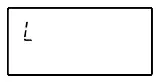 | Below measuring range error The viscosity value is below the lower limit of the viscosity measuring range. The viscosity of the sample can not be measured. This error may occur when the display unit is not connected to the main unit. |
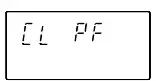 | The power supply for the internal clock is depleted. Press any key to enter the clock correction mode. Setting the clock enables the rheometer to be used temporarily. If the error occurs frequently, contact the local A&D dealer for repair. |
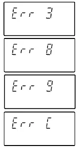 | Internal IC error Turn the power off. Then, turn the power on again. If this does not release the error, contact the local A&D dealer for repair. |
SPECIFICATIONS
| Measurement method | Sine-wave Vibrio Rheometer using the Tuning-fork Vibration method Vibration frequency 30 Hz | ||||
| Amplitude range | 0.07 to 1.2mm (At the tip of the sensor plate) | ||||
|
Viscosity measuring range | Amplitude(At the tip of the sensor plate, peak to peak[P-P]) | Viscosity range | |||
| 0.07mm | 2,000~25,000mPa・s | ||||
| 0.1mm | 20~25,000mPa・s | ||||
| 0.2mm | 0.3~25,000mPa・s | ||||
| 0.4mm | 0.3~12,000mPa・s | ||||
| 0.6mm | 0.3~5,000mPa・s | ||||
| 0.8mm | |||||
| 1.0mm | 0.3~3,000mPa・s | ||||
| 1.2mm | |||||
| Measurement accuracy*1 | Repeatability*2 | 1% (Standard deviation) | |||
| Accuracy *3 | ±3% (1~1000mPa・s) When amplitude is set to 0.4mm | ||||
|
Minimum display | Range (mPa×s) | Minimum display (mPa×s) | Minimum display (Pa・s) | ||
| 0.3~10 | 0.01 | 0.0001 | |||
| 10~100 | 0.1 | 0.0001 | |||
| 100~1000 | 1 | 0.001 | |||
| 1000~25000 | 10*4 | 0.01 | |||
| Unit (Viscosity) | mPa×s, Pa×s, cP, P | ||||
| Operating temperature | 10 to 40°C (50 to 104°F) | ||||
| Minimum sample amount | 10 mL or more | ||||
| Temperature display | 0 to 99°C/0.1°C, (32 to 210.2°F/0.1°F) *5 100 to 160°C/1°C, (212 to 320°F/1°F) | ||||
| Temperature measurement accuracy | 0 to 20°C/32 to 68°F: ±1°C/±1.8°F | ||||
| 20 to 30°C/68 to 86°F: ±0.5°C/±0.9°F | |||||
| 30 to 100°C/86 to 212°F: ±2°C/±3.6°F | |||||
| 100 to 160°C/212 to 320°F: ±4°C/±7.2°F | |||||
| Display | Vacuum fluorescent display (VFD) | ||||
| Connection cable length | 1.5 m (between the main unit and the display unit) | ||||
| Communication | RS-232C standard | ||||
| Power supply | AC adapter (Confirm that the adapter type is correct for the local voltage and power receptacle type.) | ||||
| Power consumption | Approx. 14 VA (Including the AC adapter) | ||||
| External dimensions/mass | Sensor unit: 112 (W) x 132 (D) x 291 (H) mm/Approx. 0.8 kg | ||||
| Display unit: 238 (W) x 132 (D) x 170 (H) mm/Approx. 1.3 kg | |||||
| Stand unit: 296 (W) x 314 (D) x 536 (H) mm/Approx. 4.6 kg | |||||
|
Standard accessories | AC adapter (1 pc), Connection cable (1 pc), Sample cup (Capacity: 45mL, 5 pcs), Small sample cup (Capacity: 10 mL, 5 pcs), Small sample cup cover (5 pcs), Glass sample cup (Capacity: 13 mL, 2 pcs), Glass sample cup holder (1 pc), Water jacket (1 pc), Windows communication tools Win CT-Viscosity (1 pc), RS-232C cable (1 pc), Serial-USB converter (1 pc), Stand for securing the sensor unit (1 pc), X-Y-Z stage (1 pc) | ||||
*1 When the sample cup (45mL) is used
*2 Repetitive measurement with the sensor plates remaining in the sample
*3 The value after calibration using a standard viscosity fluid at a temperature range between 20°C and 30°C with no condensation.
In a measurement that takes a long time, perform calibration using a standard viscosity fluid or purified water periodically, as necessary.
*4 The unit switches to Pa⋅s.
*5 The operating temperature of each standard and optional accessory is as follow
| Name | Temperature used |
| Sample cup-capacity 45 mL (AX-SV-33), Small sample cup-capacity 10 mL / Small sample cup cover (AX-SV-34), Sample cup-capacity 2 mL (AX-SV-58)*, Sample cup holder-For capacity 2 mL (AX-SV-56-1/2) | 0 to 120°C |
| Glass sample cup-capacity 13 mL (AX-SV-35), Glass sample cup-capacity 2 mL (AX-SV-59) | 0 to 230°C |
| Water jacket (AX-SV-37) | 0 to 100°C |
| Glass Storage Container (AX-SV-38)* | 0 to 180°C |
| Plastic Storage Container (AX-SV-39)* | 0 to 80°C |
- Lid: 80°C max
Take the operating temperature shown above into considerations when using the above items.
OPTIONAL ACCESSORIES
List of Optional Accessories (sold separately)
| Model | Name | |
| AX-SV-31-2.5 | Standard viscosity fluid (JS2.5) |
Capacity: 500 mL, with certification according to JIS Z8809 |
| AX-SV-31-5 | Standard viscosity fluid (JS5) | |
| AX-SV-31-10 | Standard viscosity fluid (JS10) | |
| AX-SV-31-20 | Standard viscosity fluid (JS20) | |
| AX-SV-31-50 | Standard viscosity fluid (JS50) | |
| AX-SV-31-100 | Standard viscosity fluid (JS100) | |
| AX-SV-31-200 | Standard viscosity fluid (JS200) | |
| AX-SV-31-500 | Standard viscosity fluid (JS500) | |
| AX-SV-31-1000 | Standard viscosity fluid (JS1000) | |
| AX-SV-31-2000 | Standard viscosity fluid (JS2000) | |
| AX-SV-31-14000 | Standard viscosity fluid (JS14000) | |
| AX-SV-31-160000 | Standard viscosity fluid (JS160000) | |
| AX-SV-33 | Sample cup (Capacity: 45 mL) 10 pcs | |
| AX-SV-34 | Small sample cup (Capacity: 10 mL) 10 pcs | |
| AX-SV-35 | Glass sample cup (Capacity: Approx.13 mL) 1 pc | |
| AX-SV-36 | Positioning Stopper 1 pc | |
| AX-SV-37 | Water jacket 1 pc | |
| AX-SV-38 | Glass storage container (Capacity: Approx.50 mL) 10 pcs | |
| AX-SV-39 | Plastic storage container (Capacity: Approx.120 mL) 20 pcs | |
| AX-SV-42 | Analog output | |
| AX-SV-43 | Extension cable (5 m) To extend the distance between the main unit and the display unit. | |
| AX-SV-51 | Stand set Stand for securing the sensor unit 1 pc X-Y-Z stage 1 pc Sample cup (Capacity: 2 mL, Lid attached) 1 pc Sample cup holder (For 2 mL capacity) 1 pc Sample cup (Capacity: 45 mL) 1 pc | |
| AX-SV-52 | X-Y-Z stage1 pc | |
| AX-SV-53-EX | Software set (Serial-USB converter included) Win CT-Viscosity 1 pc RS232C striate cable 1 pc Serial-USB converter 1 pc | |
| AX-SV-54 | Cup set(Capacity: 10 mL・13 mL・45 mL) (Water jacket attached) Sample cup (Capacity: 45 mL) 5 pcs Small sample cup (Capacity: 10 mL) 5 pcs Small sample cup cover 5 pcs Glass sample cup (Capacity: Approx.13 mL) 2 pcs Glass sample cup holder 1 pc Water jacket 1 pc | |
| AD-8121B | Compact printer | |
| AD-1682 | Rechargeable battery | |
AX-SV-33 Sample Cup
• The AX-SV-33 consists of :
Sample cup (Capacity: 45 mL) 10 pcs
(Polycarbonate, Operating temperature: 120°C max.)
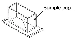
AX-SV-34 Small Sample Cup (10mL)
• Used when a small amount of sample will be measured.
– The AX-SV-34 consists of : 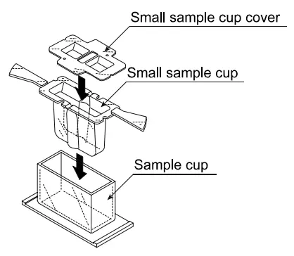 Small sample cup (10 mL) 10 pcs
Small sample cup cover 10 pcs
Sample cup 1 pc
(All: Polycarbonate, Operating temperature: 120°C max.)
AX-SV-35 Glass Sample Cup (Approx. 13 mL)
• Used when organic solvents will be measured.
– The AX-SV-37 consists of :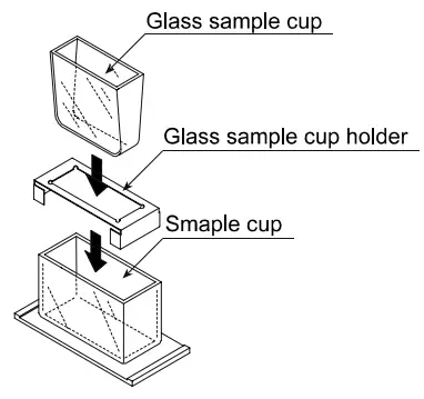 Glass sample cup (Capacity: Approx.13 mL) 1 pc
(Pyrex® glass, Operating temperature: 230°C max.)
Glass sample cup holder (Stainless steel) 1 pc
Sample cup 1 pc
(Polycarbonate, Operating temperature: 120°C max.)
AX-SV-36 Positioning Stopper
- Used to fix the position of the sensor unit and the sensor plates so that positioning the sensor plates and the sample surface is not required each time a measurement is performed in a repetitive test. See below for how to attach the positioning stopper.
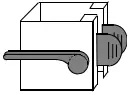
How to attach the positioning stopper:
- Raise the lever so that the sensor unit can be moved.
- While pinching the grips, lift out the sensor unit from above.
- While pinching the grips on the positioning stopper, attach the stopper, with the lever on the left side as seen from front, on the supporting post. Be sure to place the guide located on the inner wall of the stopper in the guide channels located on the supporting post.
- Position the stopper at an appropriate height. Raise the lever to secure the stopper.

- While pinching the grips, attach the sensor unit on the supporting post.
- Lower the sensor unit until it comes into contact with the stopper.
- Lower the lever to secure the sensor unit.
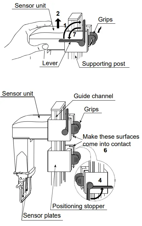
AX-SV-37 Water Jacket Assembly
- Used, in combination with a commercially available constant temperature bath for heating medium circulation, to maintain the sample temperature constant or to measure the viscosity while changing the sample temperature.
- The glass sample cup sold separately can also be used.

- The AX-SV-37 consists of :
Water jacket 1 pc
(Main body: Polycarbonate, Packing: Silicone rubber, Washer: Nylon)
Small sample cup 4 pcs
(Polycarbonate, Operating temperature: 120°C max.)
Small sample cup cover 4 pcs
(Polycarbonate, Operating temperature: 120°C max.)
Screw 1 pc
(Screw: Polyacetal, Washer: Nylon)
- Specifications Circulation nozzle: Outside diameter 10.5 mm
Recommended hose: Silicone tube, inside diameter 8 mm - It is recommended that, for safety, a commercially available tubing clamp (clamping size: 11 to 20 mm) be used to fasten the tube securely to the nozzle.
- When using the water jacket, make sure that no inner pressure is exerted in the water jacket due to the kinked or blocked tubes, as that could exert the pressure in the water jacket, causing it to break.
- When a stirrer is attached at the bottom of the water jacket, the sample viscosity can be measured while the sample is being stirred. The maximum viscosity value which can be measured is 1000 mPa×s.
Stirrer: VARIOMAG MICRO manufactured by H+P Labor Technik AG Use a rotator with a size of 6 mm (length) x 4 mm (diameter).
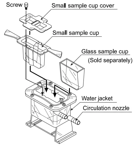

AX-SV-38 Glass Storage Container
- Used to store sample fluids.
The viscosity of the sample stored in the container can be measured as it is.
– The AX-SV-38 consists of : Glass storage container (Capacity: Approx.50 mL) 10 pcs (Borosilicate glass, Operating temperature: 180°C max.)
Lid 10 pcs
(Polyethylene, Operating temperature: 80°C max.)
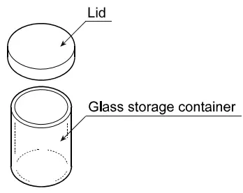 Glass storage container (Capacity: Approx.50 mL) 10 pcs (Borosilicate glass, Operating temperature: 180°C max.)
AX-SV-39 Plastic Storage Container
- Used to store sample fluids.
The viscosity of the sample stored in the container can be measured as it is.
– The AX-SV-39 consists of : Plastic storage container (Capacity: Approx.120 mL) 20 pcs (Polypropylene, Operating temperature: 80°C max.)
Lid 20 pcs
(Polyethylene, Operating temperature: 80°C max.)
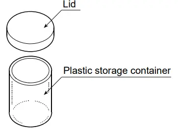 Plastic storage container (Capacity: Approx.120 mL) 20 pcs (Polypropylene, Operating temperature: 80°C max.)
AX-SV-51 Stand Set
- Used for securing the sensor unit while measuring the viscosity of a sample.
– Consists of :
Stand for securing the sensor unit 1 pc
X-Y-Z stage 1 pc
- Used when a small amount of sample (2 mL) will be measured. (Only for SV-1A/SV-1H)
– Consists of :
Sample cup (Capacity: 2 mL) 1 pc
Sample cup holder 1 pc
Sample cup (Capacity: 45 mL) 1 pc
(Polycarbonate, Operating temperature: 120°C max.)
Lid 1 pc
(Polypropylene, Operating temperature: 80°C max.)
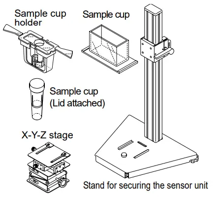
AX-SV-52 X-Y-Z Stage
• Used to support and adjust the sample cup position.
– Consists of :
X-Y-Z stage 1 pc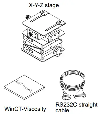
AX-SV-53-EX Software Set
• Used while acquiring the viscosity data with a personal computer.
– Consists of :
Win CT-Viscosity 1 pc
RS-232C straight cable 1 pc
Serial-USB converter 1 pc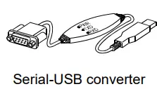 AX-SV-54 Cup Set (10 mL / 13 mL / 45 mL)
(Use the AX-SV-51 Stand Set if necessary.)
• Used when a small amount of sample will be measured.
– Consists of :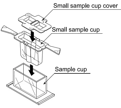 Sample cup (45 mL) 5 pcs
Small sample cup (10 mL) 5 pcs
Small sample cup cover 5 pcs
(All: Polycarbonate, Operating temperature: 120°C max.)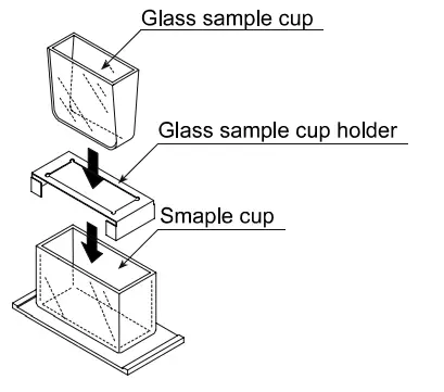 Used when organic solvents will be measured.
Glass sample cup (Capacity: Approx.13 mL) 2 pcs
(Pyrex® glass, Operating temperature: 230°C max.)
Glass sample cup holder (Stainless steel) 1 pc
• Water Jacket
Used, in combination with a commercially available constant temperature bath for heating medium circulation, to maintain the sample temperature constant or to measure the viscosity while changing the sample temperature.
– Consists of :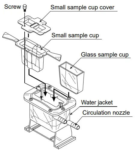 Water jacket 1 pc
(Main body: Polycarbonate, Packing: Silicone rubber, Washer: Nylon)
AD-1671A Anti-vibration table
- Used when the viscosity value is unstable due to external vibration, especially for measuring low viscosity.

EXTERNAL DIMENSIONS
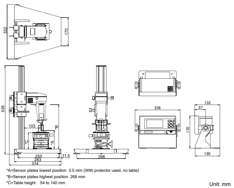
Detailed View of the Sensor Unit
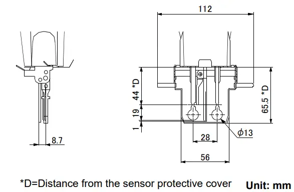
 5 Commonwealth Ave
Woburn, MA 01801
Phone 781-665-1400
Toll Free 1-800-517-8431
Visit us at www.TestEquipmentDepot.com


