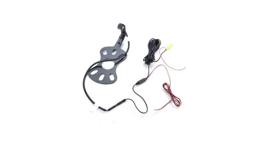
![]() SummitView™ Jeep Wrangler (JK/JL)
SummitView™ Jeep Wrangler (JK/JL)
Adjustable Rear Vision System
with CMOS Camera For Aftermarket Display
TV-884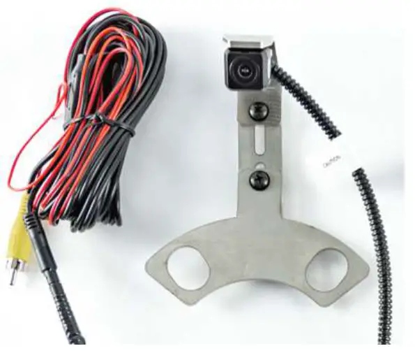
Kit Content
Kit A Components for installing the SUTV-884
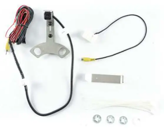
Kit Contents:
| 1x CMOS Camera |
| 1x Adjustable 5th Wheel Camera Mount |
| 1x Video Chassis Harness |
| 1x RCA to Factory 22 Pin connector |
| 3x Push Nut |
| 15x Zipties |
Install Rear View Camera Chassis Harnes
| Part 1 | Preparing the Radi |
| 1. First, you need to gain access to the back of your aftermarket radio. If you already have access, skip to part 2. 2. Start by removing the rubber bin insert from the top of the dash 3. Remove the 7mm bolt under the rubber bin insert. 4. Using a plastic trim removal tool, remove the window switch panel. 5. Disconnect harness from window switches. 6. Remove the 7mm bolt behind the window switch panel. 7. Remove driver knee bolster cover 8. Remove (2) 7mm bolts on both sides of the steering column. 9. Remove center stack/cluster trim 10. Remove the glove box for access. You will need access to the area behind the glove box to make your connection to the radio. 11. Remove (4) 7mm bolts to remove the radio from the das | 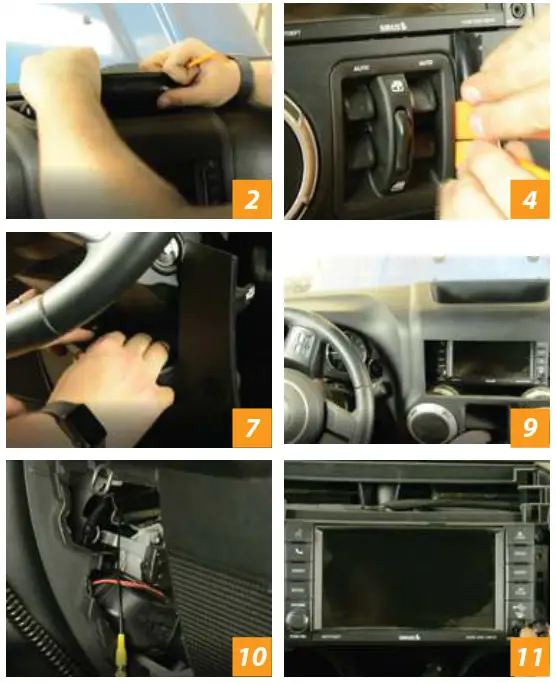 |
| Part 2 | Camera functionality test (Highly recommended, not required) |
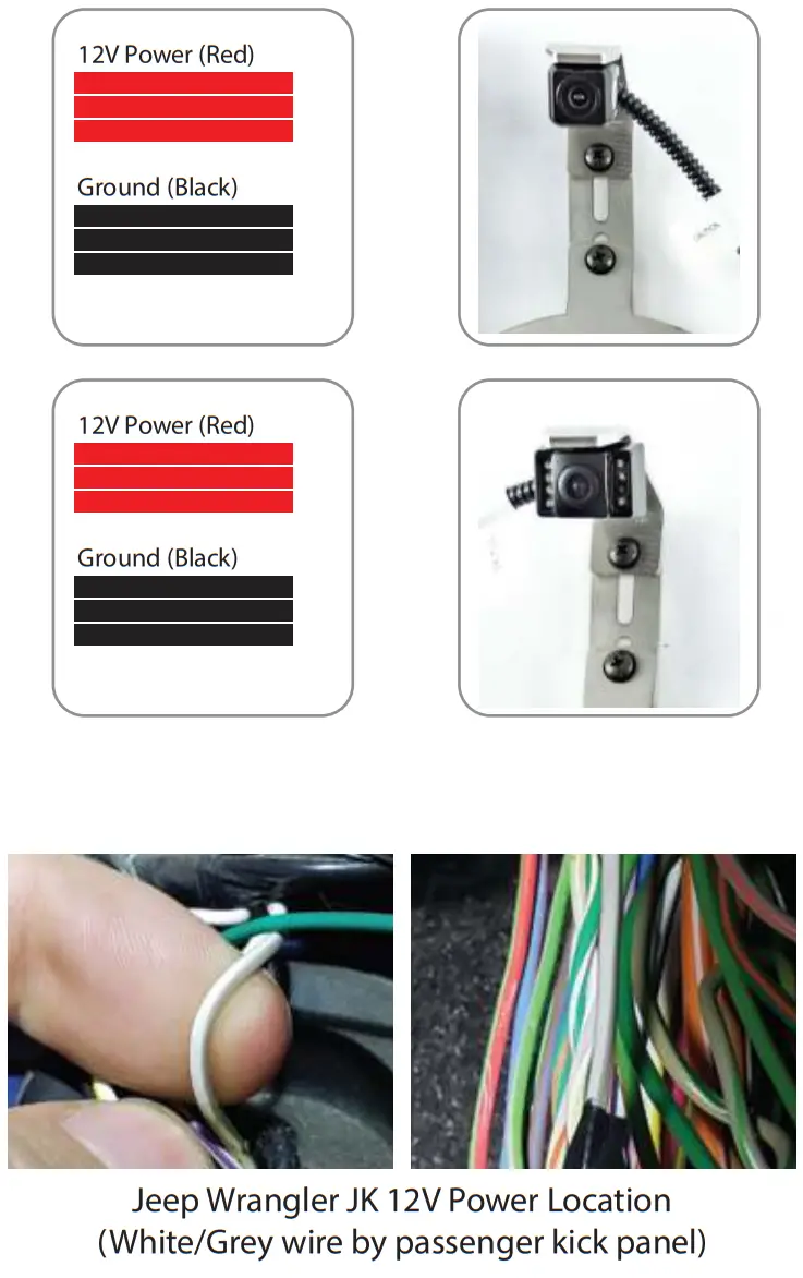
| 1. 8837: a. There will be three wires accompanying the RCA: Red, Green, and Black 1. Twist red and green together = Power 2. Black = Ground b. Using a wire extension (not supplied) 1. Connect twisted red and green directly to the positive terminal of the battery 2. Connect Black to the negative terminal of battery c. Test Camera 1. Connect RCA to Aftermarket radio and 2. Turn the Key to on position 3. Place the vehicle in reverse and verify a good image. 2. 8847: a. There will be two wires at the rear of the harness near the camera 1. Red= Power 2. Black = Ground b. Using a wire extension (not supplied) 1. Connect red wire directly to the positive terminal of the battery 2. Connect Black to the negative terminal of battery c. Test Camera 3. 8857: a. There will be two wires accompanying the RCA: Red and Black 1. Red= Power 2. Black = Ground b. Using a wire extension (not supplied) 1. Connect Red wire directly to the positive terminal of the battery 2. Connect Black to the negative terminal of battery c. Test Camera 1. Connect RCA to Aftermarket radio 2. Turn the Key to on position 3. Place the vehicle in reverse and verify a good image. 1. Connect RCA to Aftermarket radio and 2. Turn the Key to on position 3. Place the vehicle in reverse and verify a good image. | 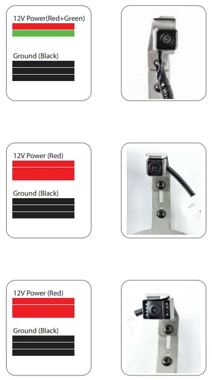 |
| Part 3 | Installing Rear Camera on Tire Carrier |
| 1. Remove your spare tire and place the camera bracket on the top two studs. 2. Secure bracket to carrier using (2) push nuts to secure the bracket on two top studs. 3. The nylon washer will go on the bottom stud and will be secured with the third push nut. 4. Place your tire on the carrier and make any needed adjustments to the camera placement to see through the wheel spokes. 5. Once the orientation is satisfactory, tighten two adjustment screws on the bracket. 6. Reinstall the spare tire on the carrier. | 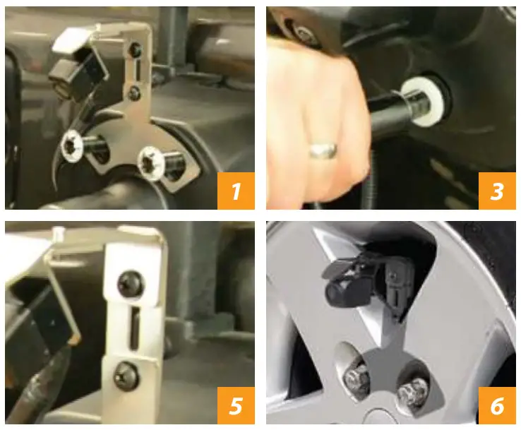 |
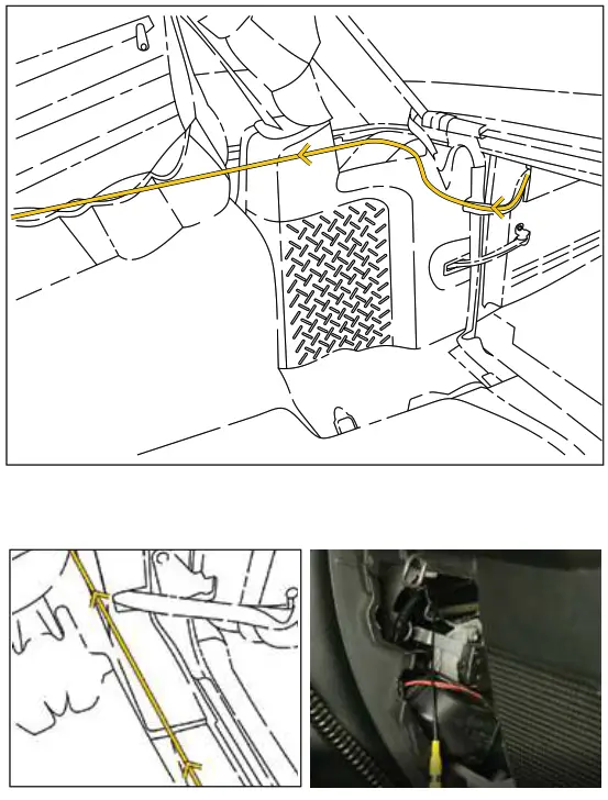
| 1. Using a plastic trim removal tool, remove interior panels on the inside of the rear gate 2. Insert the camera connector through the rear relief/vent flap behind the spare tire mount. DO NOT RUN THROUGH THE CENTER HOLE OF THE TIRE CARRIER 3. Gently pull the harness through the relief door and connect your camera harness to your chassis harness. 4. Use supplied wire ties to secure the chassis harness to the existing harness in the tailgate.5. Use supplied wire ties to secure chassis harness to the exterior of fabric factory wire cover connecting tailgate to the body. Do not run through fabric factory wire cover. CAUTION: Leave enough slack to allow the gate to open fully 6. Using a plastic trim removal tool, remove the rear access (behind seat belt) panel to expose the 10mm bolt, and remove bolt. Failure to remove this bolt will break the panel. 7. Remove the interior rear quarter panel 8. FOR 8848, you will need to ground black wire at a good chassis ground. Isolate the red wire with electrical tape. You will connect to power at the front of the vehicle in later steps. 9. Pull back the carpet and continue running the chassis harness forward under sill plates and B-pillar cover to the passenger kick panel 10. Use a plastic trim removal tool to remove the (2) plastic push pins and remove the passenger sill plate/kick panel. 11. Run the chassis harness behind the glove box and into the radio cavity. | 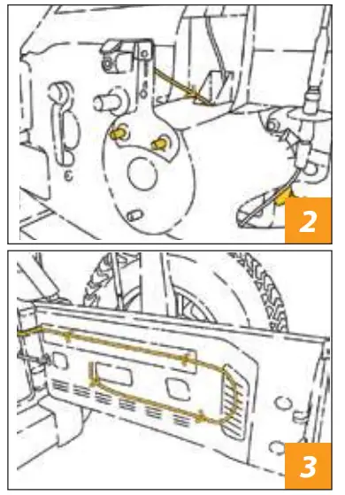
|
Connecting to Power
Part 1
| 1. 8837: a. There will be three wires accompanying the RCA in the passenger kick panel: Red, Green, and Black 1. Twist red and green together = Power 2. Black = Ground b. Identify power output from your aftermarket radio c. Connect twisted red and green wire to the power output from radio d. Connect the black wire to the Chassis ground. We recommend using factory chassis grounding point. 2. 8847: a. Identify the red power wire exiting the back of the yellow RCA from your camera chassis harness b. Identify power output from your aftermarket radio c. Connect Red wire to the power output from your aftermarket radio d. Connect the black wire to the Chassis ground. We recommend using factory chassis grounding point. 3. 8857: a. Connect jumper power harness to chassis harness (if not already connected) b. Separate power and ground wires at the jumper harness 1. Red = Power 2. Black = Ground c. Identify power output from your aftermarket radio d. Connect red wire to the power output from your aftermarket radio. e. Connect the black wire to the Chassis ground. We recommend using factory chassis grounding point. | 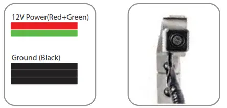
|
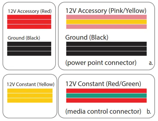
| Part 2 | Power connections in Jeep Wrangler JL / JT |
1: Remove the climate control and media control trim panels. Power Output Wrangler JL Harness |  |
Finishing Installation
Part 1
| a. Connect male RCA of chassis harness to female RCA behind the glove box. b. Test camera 1. Twist red and green together = Power 2. Black = Ground c. Reassemble vehicle in reverse order of removal | 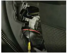 |
FAQ Section
![]() WARNING: Cancer and Reproductive Harm www.P65Warnings.ca.gov
WARNING: Cancer and Reproductive Harm www.P65Warnings.ca.gov
Installation Instructions – SUTV-8848


