MPS-400 with Keltron RCVR/XMTR Wiring Diagram
50812 Revision A1
March 5, 1999
ECN 99-107
Keltron 95M3158 TTM-RPS
- Terminals 7 and 8: Remote station alarm/trouble inputs.
- Terminals 9 and 10: Sprinkler supervisory input.
CAUTION!
For reasons of wiring diagram clarity, terminal designations of Keltron modules are not shown in actual order. Follow Keltron manual and module markings for exact terminal locations to prevent severe module damage!
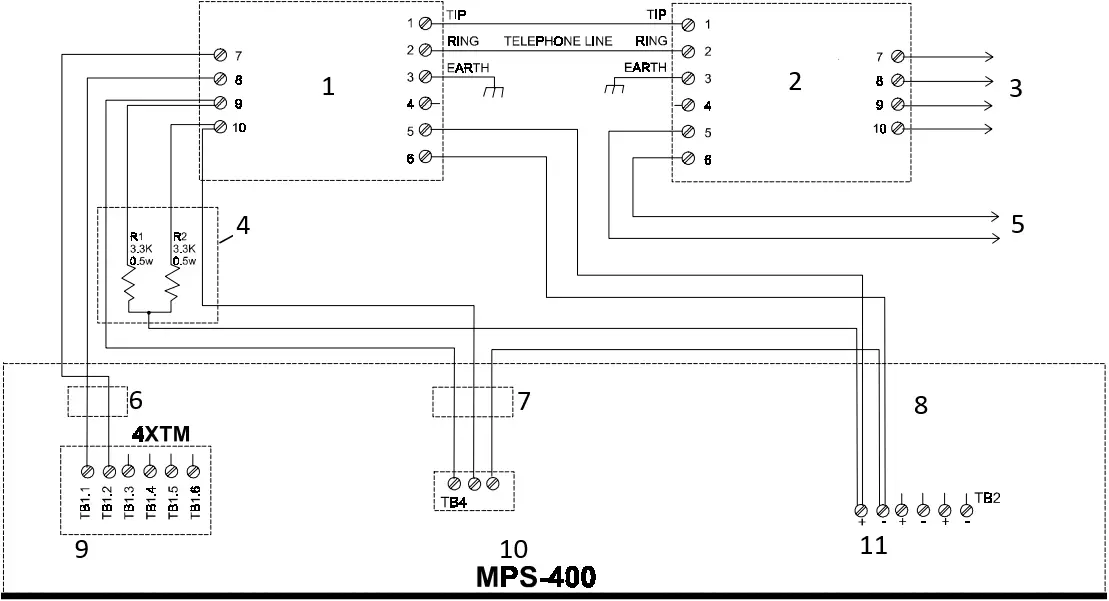
- KELTRON* 95M3158 TTM-RPS UL Listed
- KELTRON* 95M3083 TRM-RP UL Listed
- TO REMOTE* STATION
- REL-3.3K
- * TO POWER SUPPLY
- ALARM/TROUBLE SIGNAL
- SPRINKLER SUPERVISORY SIGNAL
- * For more information, refer to Keltron manual
- NOTE: Cut TBL Jumper on 4XTMF module to send alarm/trouble signals from the same pair of terminals
TROUBLE = NO SIGNAL - Note: Switch S4 on MPS-400 must be in the down position.
| LENA | TB | + | – |
| AFP-400 AFP-300 | 2 | 1 | 2 |


 Assembly Instruction Manual")