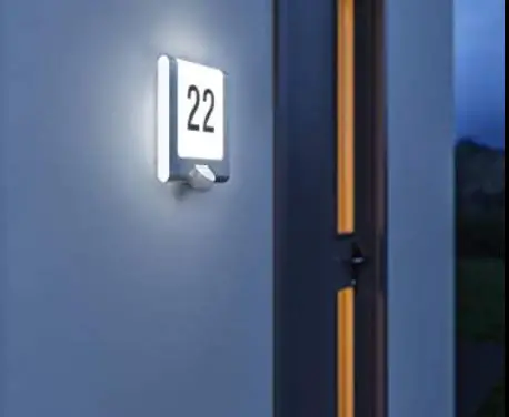
steinel L 220 S LED House Number Wall Light
 General safety precautions
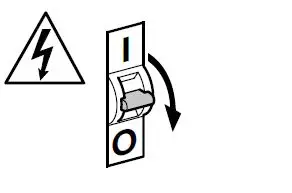
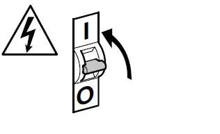
- Disconnect the power supply before attempting any work on the unit.
- During installation, the electric power cable to be connected must not be live. Therefore, switch off the power first and use a voltage tester to make sure the wiring is off-circuit.
- Installing these lights involves work on the mains voltage supply; installation must therefore be carried out professionally in accordance with the applicable national wiring regulations and electrical operating conditions
- Only use genuine replacement parts.
- Repairs may only be made by specialist work-shops.
L 240 S / L 220 S L 220
L 240 S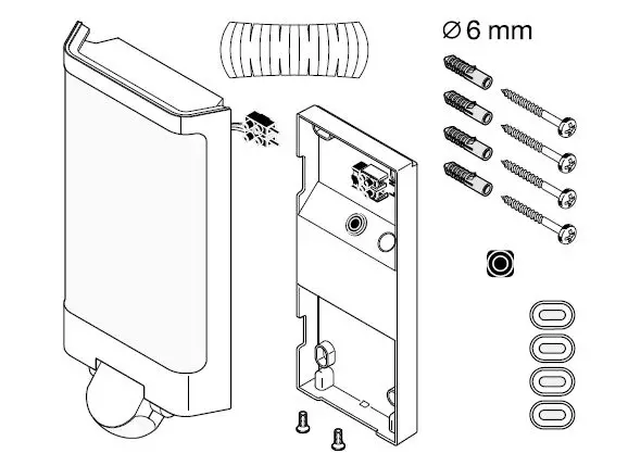 L 220 S
 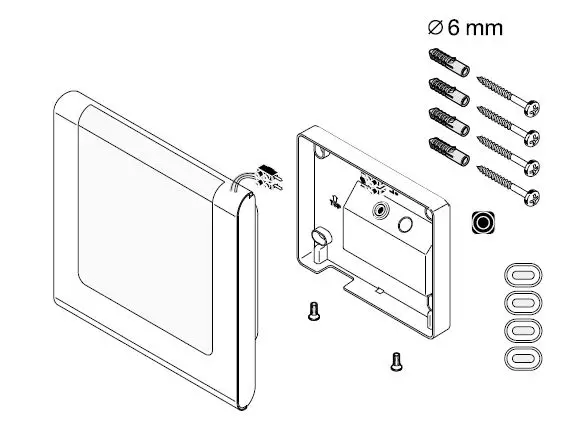 L 220
L 220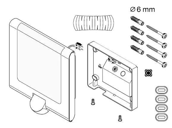
L 240 S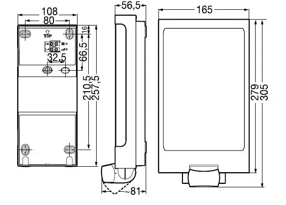
L 220 S 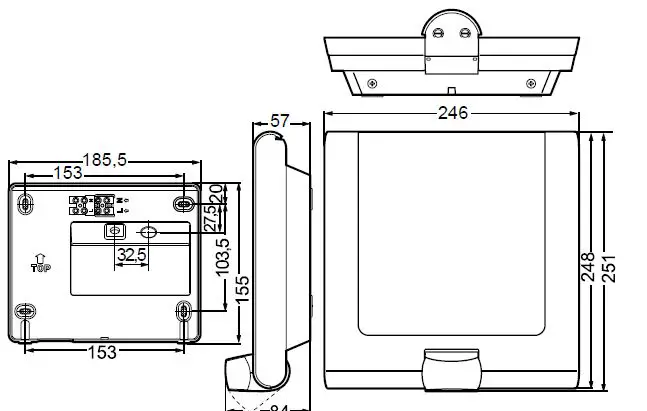
 L 220
L 220 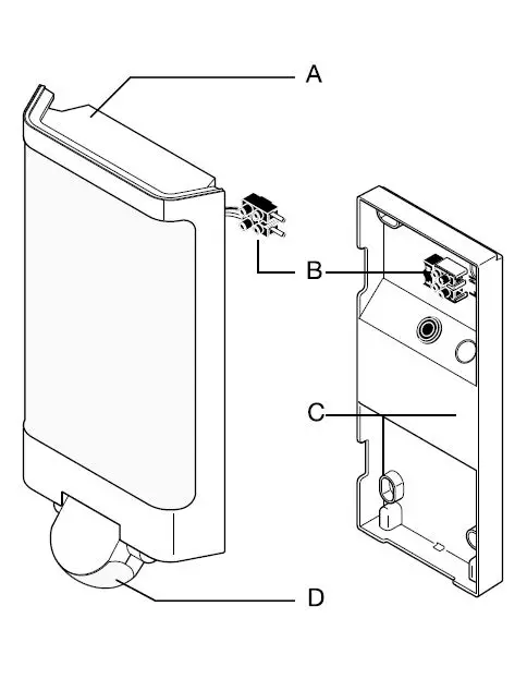 L 240 S
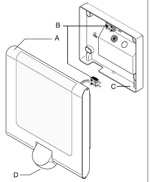 L 220 S
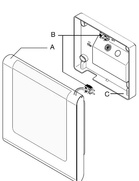 L 220 S
Proper Use
- Outdoor light with LEDs as the light source.
- Suitable for wall mounting outdoors.
- The unit is not suitable for connecting to a dimmer.

- These sensor versions (S versions) also feature an infrared sensor for detecting movement.
Operating Principle
- Outdoor lights
- LED technology
The S versions also provide these functions
- The integrated infrared sensor detects the heat radiated from moving objects e.g. people, animals.
- The heat detected in this way is converted electronically into a signal that switches the LED light ON automatically.
- The most reliable way of detecting motion is to install the unit with the sensor aimed across the direction in which a person would walk.
- Obstacles (e.g. trees, walls etc.) interrupt the line of sensor vision.
- Heat radiation is not detected through obstacles e.g. walls or panes of glass the sensor is not triggered.
- Sudden fluctuations in temperature as a result of reach is restricted when the unit is approached head on changes in weather are not distinguished from sources of heat.
Installation
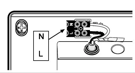
The leads consist of three wires L phase conductor (usually black, brown or grey)
N neutral conductor (usually blue)
PE protective-earth conductor (green/yellow) If you are in any doubt, identify the conductors using a voltage tester; then disconnect from the power supply again. Connect the phase conductor (L) and neutral conductor (N) to the terminal block.
 L 240 S, L 220 S
 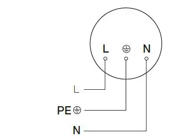 L 220
L 220 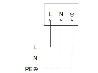 L 240 S, L 220 S
 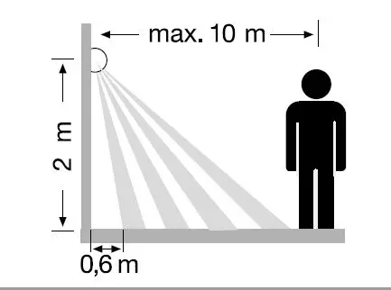 L 240 S, L 220 S
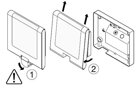

 Important
Incorrectly wired connections will produce a short circuit later on in the product or your fuse box. In this case, you must identify the individual conductors once again and reconnect them. A mains power switch for turning the unit ON and OFF may of course be installed in the mains supply lead.
Note
The light source in this light must only replaced by the manufacturer or a service engineer authorised by the manufacturer or by a similarly qualified person.
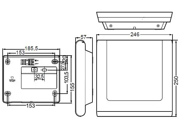
Mounting
- Check all components for damage.
- Do not use the product if it is damaged.
- Select an appropriate mounting location, giving consideration to sensor reach and mounting height
Mounting Procedure
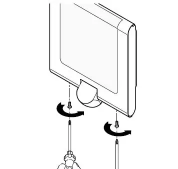
- Switch OFF power supply
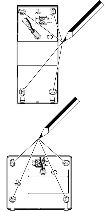
- Detach light housing from the wall mount, paying attention to the position of the sensor
- Mark drill holes .
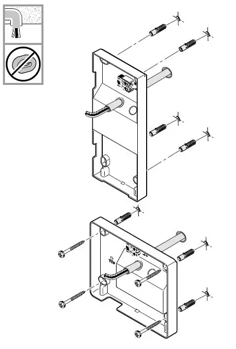
- Drill holes and insert wall plugs (concealed power supply cable.
- Drill holes and insert wall plugs (with spacers for surface power supply cable.
- Connect conductors.
- Connect plug-in connectors.
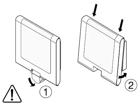
- Fit light enclosure (A) onto wall mount (C).
- Pay attention to plug-in connections as well as the position of the sensor.
- Screw light enclosure into place.
- Switch ON power supply.
- Make settings (S only).
Clean device with a moist cloth without detergent the control gear cannot be replaced.
Functions
The sensor-switched light can be put into service after mounting the light enclosure and connecting to the mains power supply.
Factory settings
Twilight setting daylight operation 2000 lux Time setting 8s
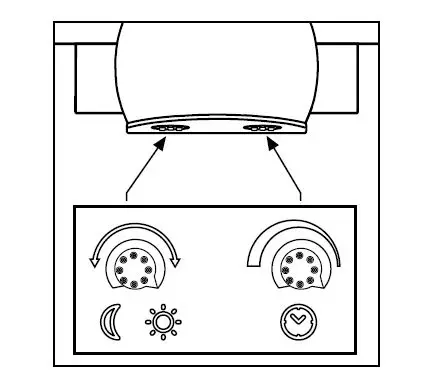
Twilight setting / response threshold S only
The sensor’s response threshold can be infinitely varied from 2–2000 lux. Control dial set to daylight operation, approx. 2000 lux. Control dial set to night-time operation, approx. 2 lux.
Time
Light ON duration can be infinitely varied from 8 s – 35 min. It is recommended that the shortest time be
selected for setting the detection zone. Control dial, shortest time = approx. 8 s. Control dial, longest time = approx. 35 min
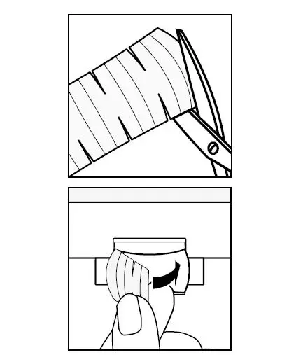
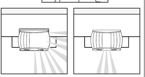
Adjusting the detection zone / reach setting
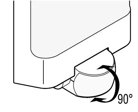
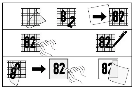
Depending on the mounting height, the detection zone setting can be optimized to suit requirements. The shroud foil can be used for masking out any number of lens segments to limit reach as required, e.g. to mask out paths or neighboring property .Reach can be adjusted from 2-10 m by tilting the sensor (D) through 90° House numbers Affix the house street number using the stickers provided
Maintenance / Care
Warning of hazards from electricity contact between water and live parts can result in an electric shock, burns or death. Only clean device in a dry state.
Risk of damage to property
Using the wrong cleaning product can damage the light.
Disposal
Electrical and electronic equipment, accessories and packaging must be recycled in an environmentally compatible manner.
Do not dispose of electrical and electronic equipment as domestic waste.
EU countries only under the current European directive on waste electrical and electronic equipment and its implementation in national law, electrical and electronic equipment no longer suitable for use must be collected separately and recycled in an environmentally compatible manner.
Manufacturer’s Warranty
This Steinel product has been manufactured with utmost care, tested for proper operation and safety and then subjected to random sample inspection. Steinel guarantees that it is in perfect condition and proper working order. The warranty period is 36 months and starts on the date of sale to the consumer. We will remedy defects caused by material flaws or manufacturing faults. The warranty will be met by repair or replacement of defective parts at our own discretion. The warranty shall not cover damage to wear parts, damage or defects caused by improper treatment or maintenance. Further consequential damage to other objects shall be excluded.
Claims under the warranty will only be accepted if the unit is sent fully assembled and well-packed with a brief description of the fault, a receipt or invoice (date of purchase and dealer’s stamp) to the appropriate Service Centre.
Troubleshooting
| Malfunction | Cause | Remedy |
| Light without power |
|
|
| Light not switching ON |
|
|
| Light not switching OFF |
|
|
| Light switches ON when it should not |
|
|
| Changing reach |
|
|
Technical specifications
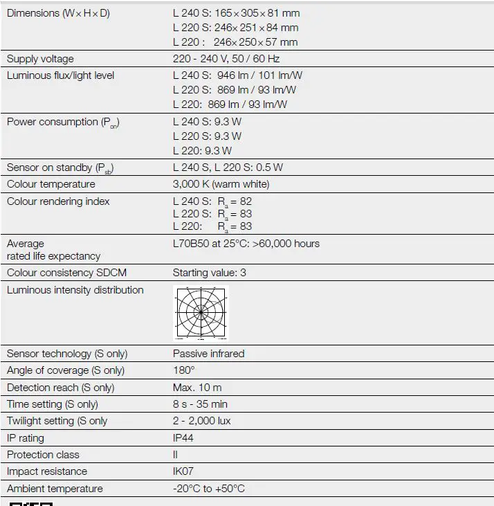
Technical documentation at www.steinel.de These products contain an energy efficiency class “D” light source.


