![]() Quick Start Guide
Quick Start Guide
PUSDM55A (P550QVF07.0)
PUSDM65A (P650QVF09.0)
PUSDM75A (SN75UNM01.0)
Package Contents
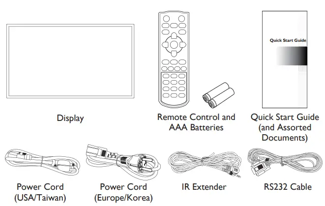
![]() NOTE: The user manual can be downloaded from https://pid.auo.com
NOTE: The user manual can be downloaded from https://pid.auo.com
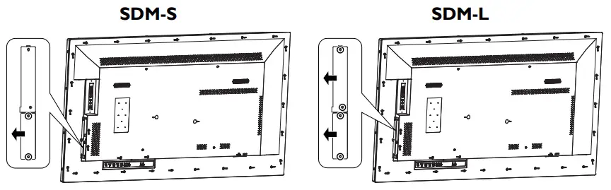
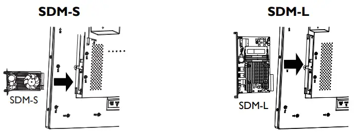
Installing an SDM Module
To install an Intel® SDM module into the SDM slot on your display:
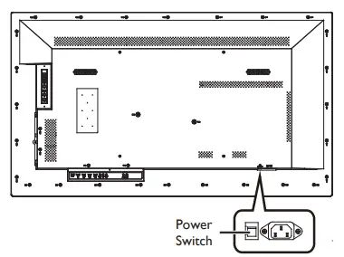
- Turn off the power switch on the display.

- [For SDM-S Modules] Remove the 2 screws securing the metal SDM-S slot cover on the right side of the display and remove the cover. [For SDM-L Modules] Remove the 4 screws securing the metal SDM-L and SDM-S slot covers on the right side of the display and remove the covers.

- Insert the SDM-S or SDM-L module into the slot.

- [For SDM-S Modules] Re-install the 2 screws to secure the SDM-S module in place. [For SDM-L Modules] Re-install the 2 screws to secure the SDM-L module in place.
- Turn on the power switch on the display.
- Power on the display and press the [SOURCE] button of the remote control to select the video input source (Slot).
![]() NOTE: Disable the “Restore On AC/Power Loss” function in the BIOS setup utility of the SDM module, otherwise the SDM module cannot be powered on normally.
NOTE: Disable the “Restore On AC/Power Loss” function in the BIOS setup utility of the SDM module, otherwise the SDM module cannot be powered on normally.
Installation
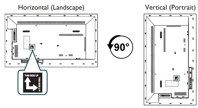
Adjusting Directions
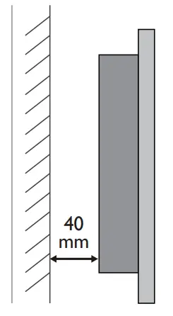
Installation on a Flat Wall (Minimum Distance: 40mm)
When installing the display on a wall face, there has to be at least 40mm of space between the display and the wall for ventilation purposes.
The display must be installed in an environment with proper ventilation to prevent it from overheating. Do not block the ventilation holes on the top, left, and right sides while keeping the display away from any heat source.
![]() NOTE: To prevent glare when used in a location with strong sunlight, it is recommended to add a cover over the display.
NOTE: To prevent glare when used in a location with strong sunlight, it is recommended to add a cover over the display.
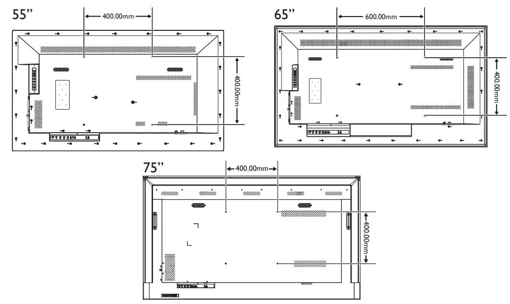
Wall Mounting
For proper installation, it is strongly recommended to use a trained, qualified technician.
The back of the display is equipped with four screw-holes with dimensions of VESA mount 400 x 400mm (for 55”/75”) or VESA mount 400 x 600mm (for 65”). Firmly secure a wall mount onto the display. Use four M6 screws on the 55″ displays (maximum length: 20mm, maximum torque: 18 kgf-cm), four M8 screws on the 65” displays (maximum length: 20mm, maximum torque: 20 kgf-cm), and four M6 screws on the 75″ displays (maximum length: 10mm, maximum torque: 18 kgf-cm).
![]() NOTE:
NOTE:
- Be careful to avoid tipping the display over when attaching accessories.
- Periodically check for loose screws, gaps, distortions, or other problems that may occur with the mounting apparatus. If a problem is detected, please refer to qualified personnel for service.
- Regularly check the mounting location for signs of damage or weakness that may occur over time.
Controlling The Display
Keypad
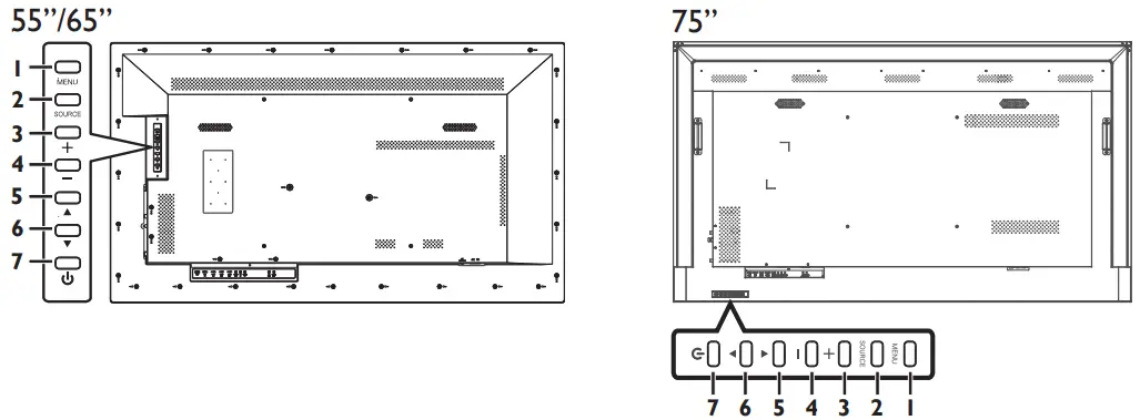
| Item | Description |
| 1 MENU | • Displays the On-Screen Display (OSD) menu. • In the sub-menu, confirms the item selected in the OSD menu and return to the previous menu. |
| 2 SOURCE | • Switches the video input source ([HDMI1], [HDMI2], [Slot], [DP]). • Accept the changes made in the OSD menu. |
| 3 Plus ( +) | • Increases the volume of the display. • Moves the selection right or increases the values in the OSD menu. |
| 4 Minus (- ) | • Decreases the volume of the display. • Moves the selection left or decreases the values in the OSD menu. |
| 5 Up ( ▲) | • Moves the selection in the OSD menu up. • Plays the media files. |
| 6 Down (▼ ) | Moves the selection in the OSD menu down. |
| 7 Power ( | Switches the power on/off. |
![]() NOTE: This button does not work when the power switch is off.
NOTE: This button does not work when the power switch is off.
• It takes about 10 seconds to power on the display.
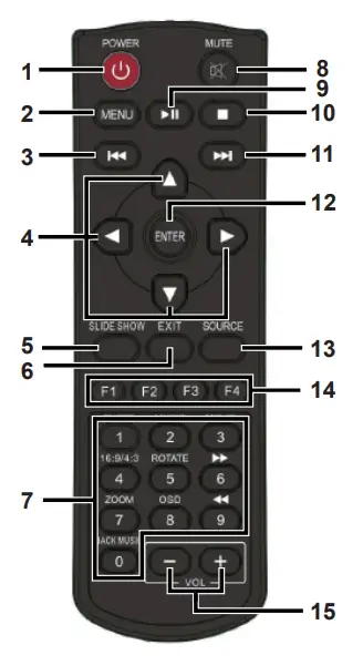
Remote Control
| Button | Description |
| 1 POWER | witches the power on/off. |
| 2 MENU | • Displays the OSD menu. • In the sub-menu, confirms the item selected in the OSD menu and return to the previous menu. |
| 3⏮️ | Plays the previous media file. |
| 4 [] / [] / [ Up / Down / Left / Right | Moves the selection in the OSD menu. |
| 5 SLIDE SHOW | Displays input source information. |
| 6 EXIT | Exits the current menu. |
| 7 Number Pad | Inputs numbers. |
| 8 MUTE | Silences the audio from the display. |
| 9⏯️ | • Plays the media file. • Pauses playback of the media file. |
| 10 | Stops playback of the media file. |
| 11⏭️ | Plays the next media file. |
| 12 ENTER | Accepts the settings made in the OSD menu. |
| 13 SOURCE | Switches the video input source. Use the [] or [] buttons to directly select [HDMI1], [HDMI2], [Slot], [DP]. |
| 14 Hot Keys | • F1: Creates a playlist for the media files that have been selected. |
| • F2: Deletes the existing playlists. • F3: Imports playlists. • F4: Sets a specific display to IR-free status. | |
| 15 VOL | Adjusts the display’s volume ([+] to increase, [-] to decrease). |
Inputs/Outputs
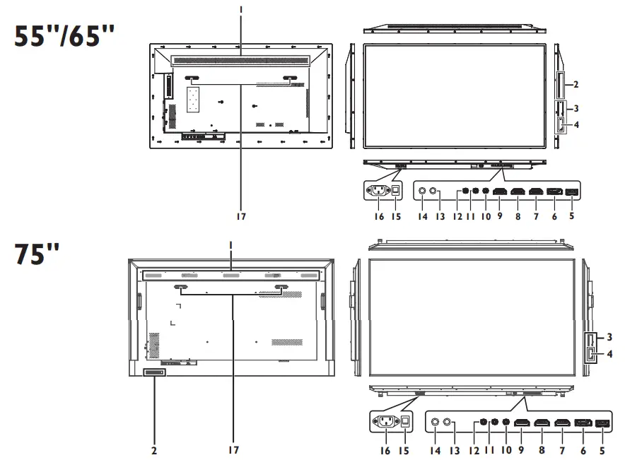
| Item | Description |
| 1 Air Vents | Disperses heat from the display. |
| 2 Control Buttons | See “Control Buttons” for detailed information. |
| 3 SDM-L | Slot used to install a large Intel® Smart Display Module (SDM Large). |
| 4 SDM-S | Slot used to install a small Intel® Smart Display Module (SDM Small). |
| 5 USB | Connects with a flash drive to display digital media or update the display’s firmware. |
| 6 DP IN | Connects with devices transmitting audio/video using the DP (DisplayPort) interface. |
| 7 HDMI IN1 | Connects with devices transmitting audio/video using the HDMI interface. |
| 8 HDMI IN2 | Connects with devices transmitting audio/video using the HDMI interface. |
| 9 HDMI OUT | Connects with the HDMI IN connector of another display to daisy chain the audio/video broadcast on the displays. NOTE: When interconnecting displays to create a daisy-chain configuration, use only the HDMI IN2 port as the input source on all the displays in the daisy chain. |
| 10 AUDIO OUT | Connects with external speakers with an amplifier or audio amplifier to output the audio that is supplied by the video source. |
| 11 IR IN | • Connects with an external IR sensor module. • Connects with the IR OUT connector of another display to daisy chain the IR signal. |
| 12 RS232 IN | Connects with the serial IO connector of a host device. |
| 13 IR OUT | Connects with the IR IN connector of another display to daisy chain the IR signal with a pin-to-pin straight cable. |
| 14 RS232 OUT | Connects with the RS232 IN connector of another display to daisy chain direct commands. |
| 15 AC SWITCH | Switches the main power on/off. |
| 16 AC IN | Connects with the supplied power cord. |
| 17 Speakers | Emit audio from the display. |
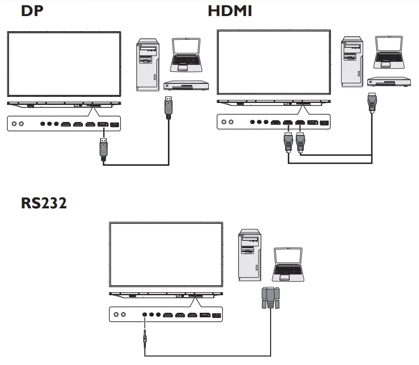
Connecting To The Display
Safety Information
Carrying the Display
When carrying the display, always carry it using both hands and with the LCD panel facing forward. DO NOT carry the display while putting pressure on the screen at the front of the chassis.
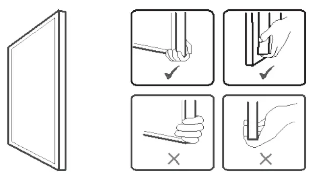
![]() CAUTION: Avoid applying force or using sharp objects on the screen or the frame around the screen at all times.
CAUTION: Avoid applying force or using sharp objects on the screen or the frame around the screen at all times.
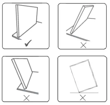
Placing the Display
When placing the display, always keep the screen face down as illustrated in the Setting Down the Display section. Never tilt the display towards the left, right, or balance on a single corner of the frame.
Setting Down the Display
When setting the display down, place the screen face down on a flat and stable surface covered by a protective sheet and a table cushion as shown in the illustration provided.
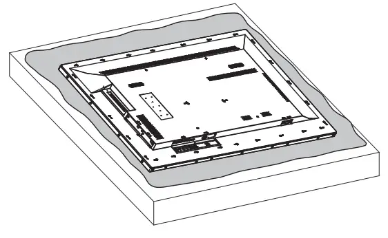
![]() CAUTION: Never press or place anything on the back cover. This may damage the internal parts of the display.
CAUTION: Never press or place anything on the back cover. This may damage the internal parts of the display.