OY1400 Industrial Communication and Control Unit

OY1400 Industrial communication and control unit manual
This manual offers a simple 5-step guide for getting started with the sensor, as well as configuration with Talkpool’s Sensepool visualization layer and information for advanced users.
The OY1400 Industrial communication and control unit is designed with focus on ease-of-use and reliable operation in LoRaWAN networks. The product is suited for a huge variety of use cases, as external probes can be connected to the unit. Normal users will only need to read the 5-step guide at the beginning of this manual.
Digital activation
Upon receiving your OY1400 Industrial Control and communication unit you should first provision it to your network server. The product comes with the following:
1. Dev EUI (also can be found on the outside of the unit)
2. App Key These codes are unique for each sensor.
The Dev EUI can be seen as a simple identification code, the App Key is a securely generated authentication code.
The first step you should take is to simply provision the network server, this can be Talkpool’s solution called Sensepool or any other system that you would like to integrate the sensor with, with your App EUI.
The second step is to provision the application server with your unique Dev EUI and App Key.
Digital activation process
- Provision network server with App EUI
- Provision application server with unique Dev EUI and App Key
After the digital activation the sensor has to be physically activated and installed.
Physical installation
 When the sensors have been digitally configured it is time to physically activate and install them. The OY1400 Industrial communication and control unit can be used for dozens of unique use cases, which are of course all slightly different in installation. This is a general guideline to get started with the sensor.
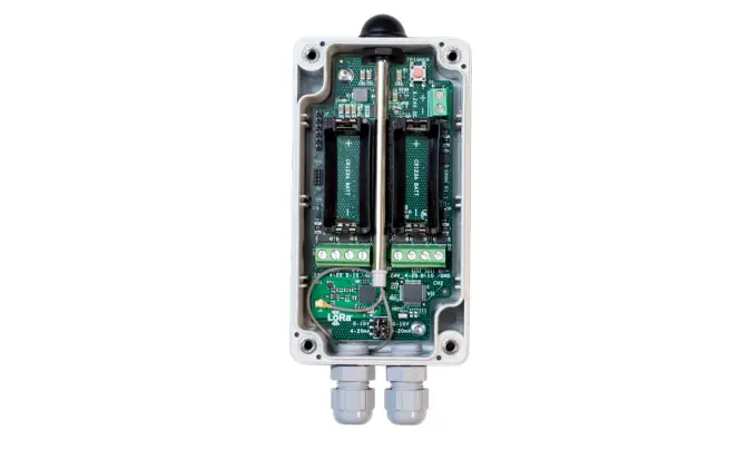
The product comes with 2 batteries and a plug. The plug is meant for when you only wish to use one of the probe inputs, so you can plug the other one to close it off and protect it from water or dust. The product has 2 openings in the backside for wall mounting.
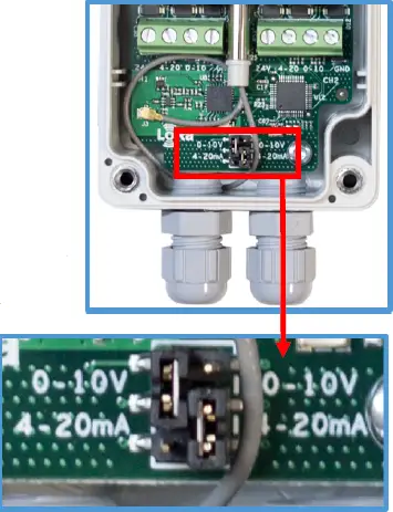
After you open the OY1400 with a screwdriver you can connect the external probe(s) to the desired slot (more on that in the next chapter). The next step is to correctly set the jumpers, depending on what kind of probe you would like to use. As can be seen in the picture to the right, you can set the jumper either to 0-10V or 4-20mA, which should correspond to the probe you are connecting. In this picture, the jumper on the left side is set to 0-10V, the jumper to the right side is set to 4-20mA. In the case you connect a probe to the 24V option, one of your probe’s threads goes into the 24V option, the other one in either 0-10V or 420mA and possibly a third into the ground option (indicated GND). Then you set the jumper accordingly (either 0-10V or 4-20mA).
After that you install the (replaceable) batteries, which activates the unit, you close the box and start measuring your data!
Physical installation process
3 Open the unit, install probes and set jumpers
4 Install batteries, activating the sensor
5 Close unit and install in location, you can now view the first data coming in on your application server
If you require further support, please contact [email protected] or your vendor. If you require more advanced information on the OY1400 Industrial Communication and control unit, please check the next sections.
Sensor connection
The OY1400 supports up to two sensors. Each sensor can independently be configured either to measure 0-10V or 4-20mA. It is also possible to configure a threshold for a channel and then the channel becomes digital and the measurement is only 0 or 1.
Voltage measurement
Each channel can independently be setup to measure a 0-10V signal. The input is 24V tolerant.
Setting up a channel for voltage measurement is done by configuring the input selection jumper to position “0-10V”, left side of the jumper block is channel 1 and right side is channel 2.
The measurement on the LoRa network shall be multiplied by a factor of 4.1 to get the correct measured voltage.
Current measurement
Each channel can independently be setup to measure a 4-20mA signal. The shunt resistor is 120 Ohm.
Setting up a channel for current measurement is done by configuring the input selection jumper to position “4-20mA”, left side of the jumper block is channel 1 and right side is channel 2.
The measurement on the LoRa network shall first be multiplied by a factor of 4.1 (to get a voltage reading across the shunt resistor) and then divided with by 120 to get the correct measured current.
Digital measurement
Each channel can independently be setup to make a “digital” measurement. This is done by configuring a threshold. When the measured voltage is above the threshold the signal is considered to be “1”, otherwise it is considered to be “0”.
The benefit of configuring the channel as digital is that the transmission requires less power.
The threshold can be configured using a downlink command. Configuring the threshold to 0 makes the channel analog.
As an example, a threshold of 5V is achieved by configuring a threshold value of 9756 (0x261C), 9756 * 1/8mV * 4.1 = 5000mV.
Standard measurement cycle
For the standard application type the measurement cycle measures both channels simultaneously. The measurement cycle is performed with a configurable period. First the 24V power output is enabled. Then there is a configurable delay before both channels are measured. This delay must be set to match the slower of the two channels. After the measurement the 24V power is disabled directly.
Manual trigger
It is possible to trigger a measurement manually by pressing the button of the OY1400. The measurement cycle is performed directly and the measurement is then transmitted (regardless of measurement grouping setting),
Measurement grouping
In order to reduce the power consumption, it is possible to configure the OY1400 to group a number of measurements in one transmission.
Applications type
It is possible to order a different application type than the standard. An application specific type typically has a customized measurement cycle including specific logic.
It is possible to read the Application type using downlink but it can only be configured during production.
The standard application is type 0. LoV application type The LoV (“Luft och Vatten”) application is type 1.
Protocol
Payload Data
This describes the payload data that is sent to and from the application server.
Uplink command device => network | ||||
Field | Bytes | Value | Description | Note |
Type | 1 | xx | 0x01: Data 0x02: Command NACK | |
Index | 1 | xx | Command Index | |
Data | As defined for Command Index (only for Type: Data) | |||
Downlink command network => device | ||||
Field | Bytes | Value | Description | Note |
Type | 1 | xx | 0x01: Set 0x02: Query 0x03: Action | |
Index | 1 | xx | Command Index | |
Data | As defined for Command Index | |||
Startup sequence
When the device has joined the network, startup transmissions are performed in order to make it easier to configure the device using downlink commands. When the startup sequence is completed normal operation is started.
There are at least five startup transmissions. The Status command (index 0x20) is sent unless a reply to a downlink is sent. If no replies are sent the Status commands are sent with increasing intervals starting with 15 seconds and ending with two minutes.
Please note that high humidity can cause condensation on the sensor, giving readings at or over 100% humidity up to 110%. The sensor will have to dry up first before accurate readings can be measured again
Commands
Index | Description | Datatype | Encoding | Valid range | Access | Unsolicited | Description | Note |
0x03 | FW build hash | 6 x Uint8 | Query | No | Unique number that identifies the firmware version | |||
0x05 | Device reset | Action | No | Reset of device | ||||
0x06 | CPU voltage | Uint8 | 25mV/ LSB | 0-3.6V | Query | No | Read CPU voltage. Max/min ranges depend on battery chemistry. | |
0x0A | CPU temperature | Uint16 Big endian | 0.01C / LSB | -50- +125 C | Query | No | Temperature from CPU sensor with 50 °C offset. Approximately 5 °C accuracy. | |
0x21 | Sensor values Ch1 Analog Ch2 Analog | TxGroupSize * (Uint16, Uint16) Big endian | 1/8 mV 1/8 mV | 0-26400 0-26400 | Query | Yes | Sensor reading when both Ch1 and Ch2 are analog. | The payload length can be used to determine the number of measurements that are grouped. |
0x22 | Sensor values Ch1 Digital Ch2 Analog | TxGroupSize * (Uint8, Uint16) Big endian | – 1/8 mV | 0-1 0-26400 | Query | Yes | Sensor reading when Ch1 is Digital and Ch2 is Analog. | |
0x23 | Sensor values Ch1 Analog Ch2 Digital | TxGroupSize * (Uint16, Uint8) Big endian | 1/8 mV – | 0-26400 0-1 | Query | Yes | Sensor reading when Ch1 is Analog and Ch2 is Digital. | |
0x24 | Sensor values Ch1 Digital Ch2 Digital | TxGroupSize * (Uint8, Uint8) Big endian | – – | 0-1 0-1 | Query | Yes | Sensor reading when both Ch1 and Ch2 are analog. | |
0x25 | Application type | – | 0-1 | Query | No | 0 = Standard application 1 = LoV application | ||
0x26 | Measurement interval | Uint16 Big endian | Minutes | 1-10080 | Query Set | No | Measurement interval in minutes | |
0x27 | Tx Group size | Uint8 | – | 1-12 | Query Set | No | Number of measurements to group in each transmission. | |
0x28 | Sensor delay | Uint16 Big endian | ms | 0-20000 | Query Set | No | Delay between activation of the 24V power and the measurement of both channels. | |
0x29 | Ch1 Threshold | Uint16 Big endian | 1/8 mV | 0-26400 | Query Set | No | Threshold setting for the digital sensor. Setting the threshold to 0 makes Ch1 analog. | |
0x2A | Ch2 Threshold | Uint16 Big endian | 1/8 mV | 0-26400 | Query Set | No | Threshold setting for the digital sensor. Setting the threshold to 0 makes Ch2 analog. |
Examples
Uplink: 012147901738
Single measurement result when both Ch1 and Ch2 is configured as analog channels. Ch1 is 2.29V and Ch2 is 0.743V. If configured for voltage
measurement this would translate to 9.389V and 3.0463V. If configured for current measurement this would translate to 19.083mA and
6.192mA.
Uplink: 0121479017383860218832482520
Three combined measurements when both Ch1 and Ch2 is configured as analog channels. Ch1 is 2.29V, 1.804V and 1.609V for the first, second
and third measurement. Ch2 is 0.743V, 1.073V and 1.188V for the first, second and third measurement.
Uplink: 0122011738002188 Two combined measurements when Ch1 is configured as digital and Ch2 is configured as analog. Ch1 is 1 and 0 for the first and second measurement. Ch2 is 0.743V and 1.073V for the first and second measurement.
Uplink: 0123479000 Single measurement when Ch1 is configured as analog and Ch2 is configured as digital. Ch1 is 2.29V and Ch2 is 0.
Uplink: 01240101000100000001 Four combined measurements when both Ch1 and Ch2 is configured as digital channels. Ch1 is 1, 0, 0 and 0. Ch2 is 1, 1, 0, 1.
Downlink: 012605A0
Uplink:
012605A0
Sets the measurement interval to 1440 minutes = 24 hours.
Downlink: 0227
Uplink:
012702
Query the Tx group size. The reply is 2 combined measurements.
Downlink: 0305
Uplink: This resets the device, bringing it back to an inactive state.
Commands
CID | Command | Transmitted by | Short Description |
0x02 | LinkCheckReq | End-device | Used by an end-device to validate its connectivity to a network. |
0x02 | LinkCheckAns | Gateway | Answer to LinkCheckReq command. Contains the received signal power estimation indicating to the end-device the quality of reception (link margin). |
0x03 | LinkADRReq | Gateway | Requests the end-device to change data rate, transmit power, repetition rate or channel. |
0x03 | LinkADRAns | End-device | Acknowledges the LinkRateReq. |
0x04 | DutyCycleReq | Gateway | Sets the maximum aggregated transmit duty cycle of a device |
0x04 | DutyCycleAns | End-device | Acknowledges a DutyCycleReq command |
0x05 | RXParamSetupReq | Gateway | Sets the reception slots parameters |
0x05 | RXParamSetupAns | End-device | Acknowledges a RXSetupReq command |
0x06 | DevStatusReq | Gateway | Requests the status of the end-device |
0x06 | DevStatusAns | End-device | Returns the status of the end-device, namely its battery level and its demodulation margin |
0x07 | NewChannelReq | Gateway | Creates or modifies the definition of a radio channel |
0x07 | NewChannelAns | End-device | Acknowledges a NewChannelReq command |
0x08 | RXTimingSetupReq | Gateway | Sets the timing of the of the reception slots |
0x08 | RXTimingSetupAns | End-device | Acknowledges RXTimingSetupReq command |
Special pre-configurations
The OY1400 is available with a number of pre-configured probes.
OY1400 Leakage rope
OPN: TP-T1400-WLR-1-EU
The device is pre-configured for the water leakage rope. It’s based on the standard OY1400 with 0-10V settings. There are 2 different payloads available:
No leakage=01240000 ; Leakage=01240100.


