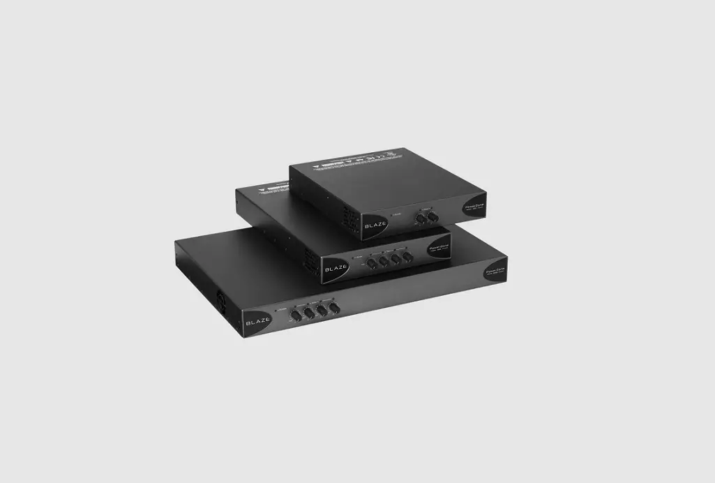
BLAZE PowerZone 1004 Power Amplifier User Guide

Carton Contents
- Amplifier unit
- Output connector x 1 or 2
- Mains power cable
- Adhesive rubber feet x 4
- Input connector x 1 or 2
- Document pack
- GPIO socket connector
- Rack Ears (PowerZone 1004)
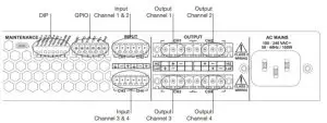
Connections
DIP Switch Functions
| SWITCH | OFF↓ | ON↑ | |
| 1 | Channel 1 in Low-Z mode | Channel 1 in Hi-Z mode | |
| 2 | Channel 2 in Low-Z mode | Channel 2 in Hi-Z mode | |
| 3 | Channel 3 in Low-Z mode* | Channel 3 in Hi-Z mode* | |
| 4 | Channel 4 in Low-Z mode* | Channel 4 in Hi-Z mode* | |
| 5 | 70V Hi-Z mode (for channels in Hi-Z mode) | 100V Hi-Z mode (for channels in Hi-Z mode) | |
| 6 | Input ganging 1: All | Input ganging 1:1 | |
| 7 | GPIO standby polarity NO (Normally Open) | GPIO standby polarity NC (Normally Closed) | |
| 8 | Front panel control locked. | Front panel control unlocked. |
* Not applicable to two channel amplifiers.
Installation Notes
- Ensure that rack or other confined installation does not restrict the airflow required for safe and reliable operation of the equipment. It is important to ensure that the 40°C maximum operating temperature for the equipment is not exceeded.
- Amplifiers will not switch on from standby mode unless an input signal is present or the standby switch is toggled.
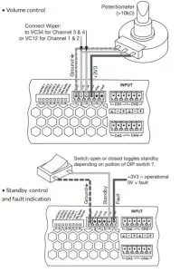
GPIO Functions
Support
- A full user manual that includes information on installation, mounting accessories and amplifier operation is available online. Go to www.blaze-audio.com or scan the QR code.