
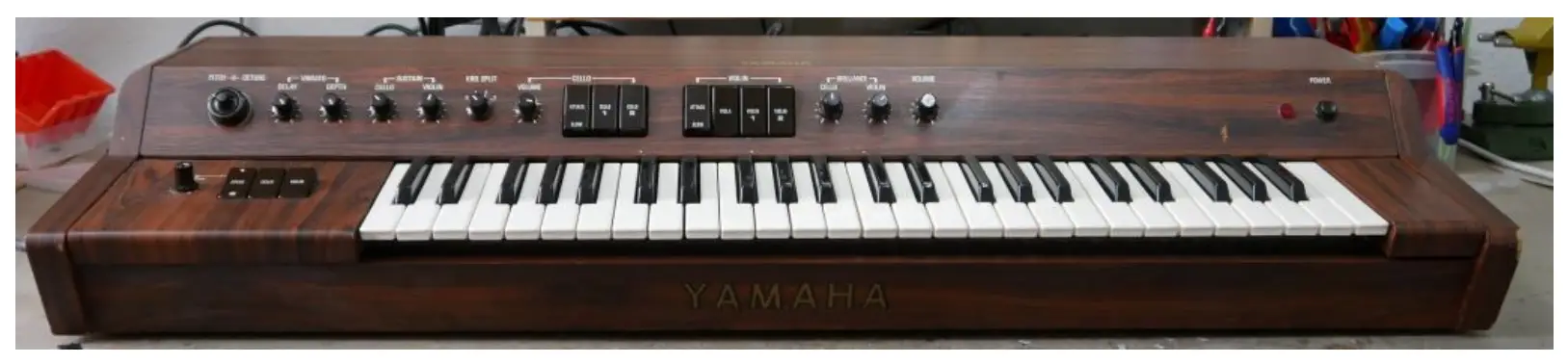
Tubbutec OrganDonor Yamaha SS-30 Instruction Manual
Tools you will need
- Soldering iron
- Wire stripper
- Metal drill 3.5mm (or similar)
- Metal drill for a 15mm hole (stepping drill for example)
- Center punch
- Screw driver
Included in the kit
- OrganDonor Main Board
- 4x organ Donor Switch Board, 2x16pin Connector, 1x20pin connector, 1x Single Switch
- Analog switch connection: 3×16 – 9cm, 1x20p – 9cm
- Interconnect cables: 1x 42cm, 3x 13cm
- Midi connector assembly
- Power connector
- Learn button
- 2x screw 2,9×6,5, 4x screw M3x16mm
- Midi socket drill guide
- 2x M3 bolt, 2xM3 nut for midi socket
Principle of operation
OrganDonor uses analog switches to simulate keyboard presses directly. Normally this would require to solder two wires for each key. Luckily this can often be avoided by grouping common signals. OrganDonor features solder jumpers to connect common signals on the back of each analog switch board.
In the case of the Yamaha SS-30 there is one common signal.
Preparation
After the first batch of OrganDonor we decided to consolidate different synthesizer models in one kit where reasonable.
That means that there might be more screws than needed for your model, or the wires are too long, or there might even be a wire assembly you don’t need for your installation. So don’t get confused.
But most importantly this also means you have to solder the shrouded headers to the switch boards, and solder the little jumpers on the backside of the switchboards.
Here’s how to do it:
Switchboard 1
20pin Header – make sure to install the header on the top side of the board. Solder the jumpers on the backside of the board as shown.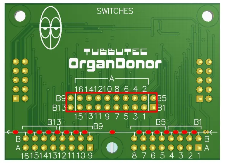
Switchboard 2
16pin Header – make sure to install the header centered on the top side of the board. Solder the jumpers on the backside of the board as shown.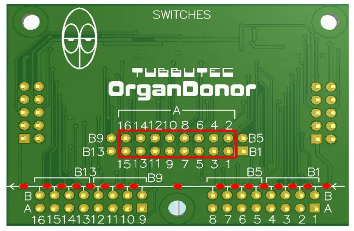
Switchboard 3
16pin Header – make sure to install the header centered on the top side of the board. Solder the jumpers on the backside of the board as shown.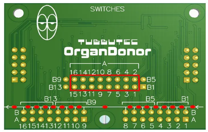
Switchboard 4 (Single Switch)
We already soldered the jumper on this board, you can use it as is.
Switch board installation
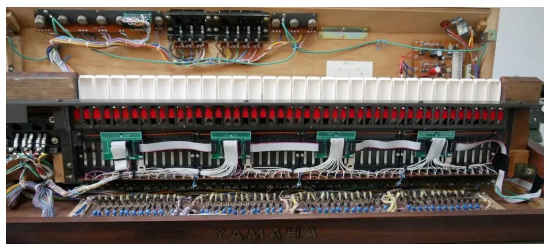
Mount the switch boards on the underside of the keyboard as shown in in the picture using the M3x16mm screws. The board on the right side has the 20pin connector, the 2 middle boards have 16pin connectors, and the leftmost board is the single switch board (Pictured is a half-populated switch board, because when we installed OrganDonor in this SS-30 the single switch boards weren’t yet available. But you get the idea. Once you have the single switch board in front of you it becomes pretty obvious how to install it.)
To mount the switchboard you need to unscrew the white plastic bracket.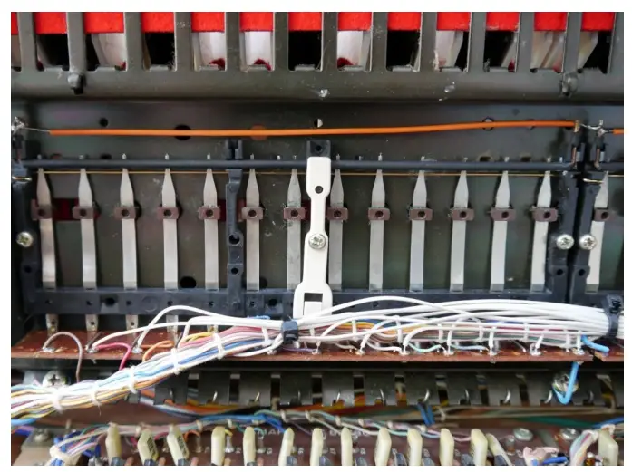
After you removed the white plastic bracket it should look like this: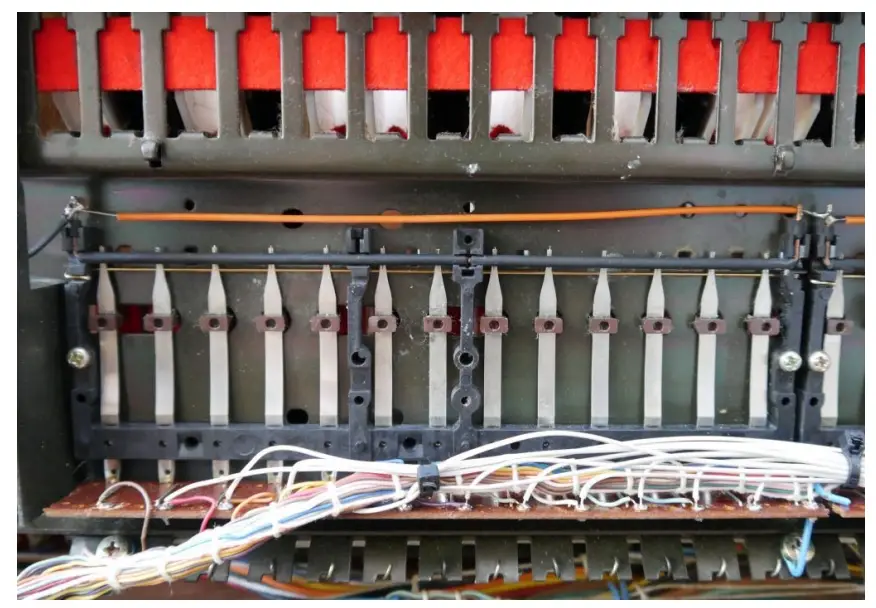
Then take 1 of the M3x16mm screws and screw the switch board and the white plastic brackets back in place.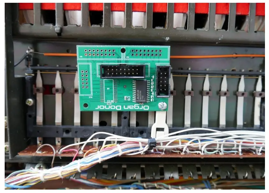
Do that for all 4 switch boards.
Please note that the board are installed upside down in reverse order (counting from right to left) to make sure we don’t need a too long interconnection cable between the main board and the first switch board. That also means the key assignment is reversed, switch 1 triggers the highest note and switch 49 triggers the lowest note. Keep that in mind should you wish to play with the configuration!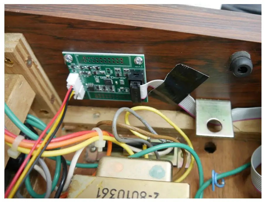
Mount the main board with the 2 2,9×6,5 screws as shown in the picture.
It is advisable to mark the two holes with a marker and pre-drill a pilot hole. It is much easier to screw in the screws this way.
Use the interconnect wires to connect the main board and the 4 switch boards.
This is how we routed the interconnection cable from the main board to switch board 1, see also the picture of the main board placement. Make sure the cable doesn’t get squished when closing the synthesizer.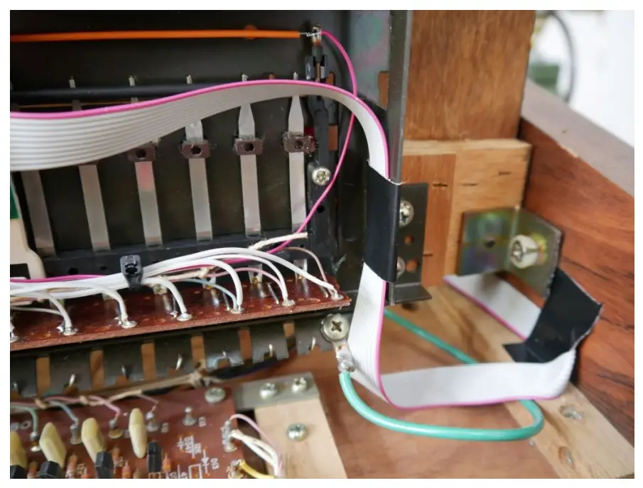
Installing the key contacts
Cut the ribbon cables to length and strip the wires.
Switch board 1:
The first wire of the 20 wire ribbon cable gets soldered to the common contact.
Wire 2 gets cut.
Wires 3-18 get soldered to the first 16 key contacts. Be careful not to desolder the internal wires.
Wires 19 and 20 get cut.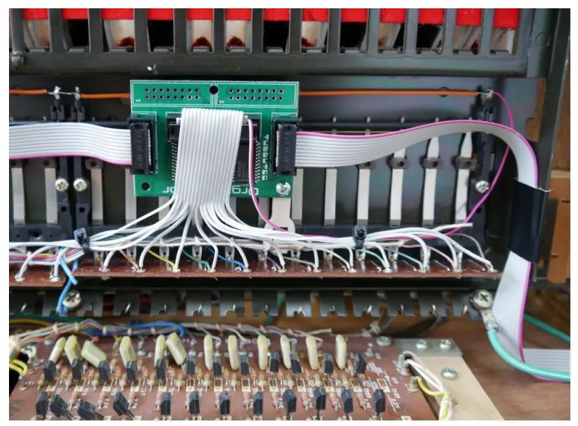
The red-striped wire is the common connection which gets soldered to the common bus bar in the upper right corner.
Switch board 2:
Wires 1–16 get soldered to key contacts 17–32.
Switch board 3:
Wires 1-16 get soldered to key contacts 33-48.
Switch board 4 (Single Switch):
The wire gets soldered to key contact 49.
Power connection
You need to extend the included power wire assembly.
Solder the yellow cable of the assembly to the yellow cables on board LC82810, the black one to the black one, and the red one to the brown one. Make sure there are no shorts!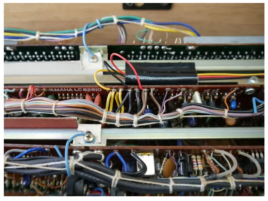
Installing the midi socket
The midi socket can be installed on the back of the machine like we did.
Use the provided drill guide to center punch the locations of the 3 holes.
The two small holes need to be about 3.2mmm to 3.5mm in diameter, the large hole 15mm. Here we typically use a stepping drill.
After drilling the holes you can unscrew the 6 screws of the jack mounting plate. That way it’s much easier to install the Midi socket.
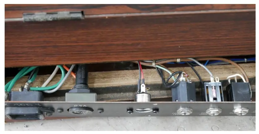
After installation it should look something like this.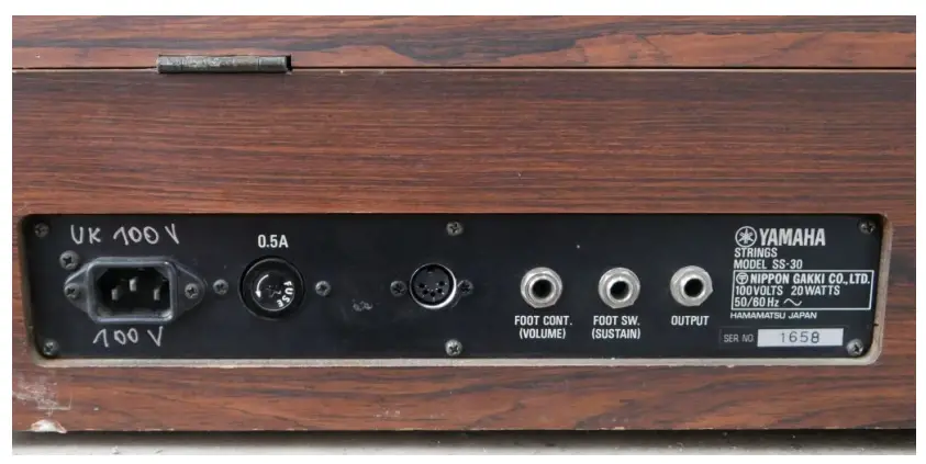
The optional learn button can be used to set midi channel. It needs to be connected to the IO “2” and “G” pin on the main board. (The back of the main board has labels on it). Wires are not included in the kit. Press the learn button and while it is pressed send a midi note on any midi channel. organDonor will use this midi channel from now. These settings are saved.
Configuration
You need to flash the corresponding configuration file to OrganDonor using our configuration tool.
The configuration tool can also be used to experiment with settings and key assignments.
You`ll find the configurator here:
https://tubbutec.de/files/organDonor/tubbutecOrganDonorConfigurator.html
This is a browser application, it works with Chrome and Safari right away, Firefox needs to be configured for web MIDI. The configurator allows you to upload your settings directly from your browser to Organ Donor, safe and load settings and export settings as SysEx files for uploading to Organ Donor via another SysEx tool.


