![]() Secure® Connect™
Secure® Connect™
Operations/Mantence Manual
REF 521200380100
Connected Hospital®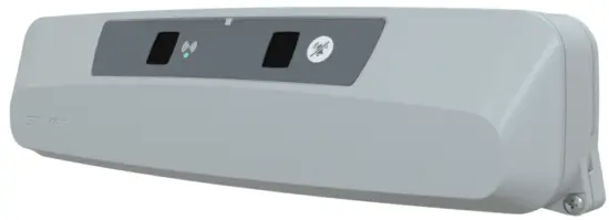
 5212-009-211
Symbols
| Refer to instruction manual/booklet | |
 | Consult instructions for use |
 | General warning |
 | Caution |
 | Non-ionizing radiation |
 | China RoHS with declarable substances |
| REF | Catalogue number |
| SN | Serial number |
| MD | European medical device |
 | CE mark |
| Authorized representative in the European Community | |
| US Patents | For US Patents see www.stryker.com/patents |
 | Manufacturer |
| IP×4 | Protection from liquid splash |
 | Class II electrical equipment: equipment in which protection against electric shock does not rely on basic insulation only, but in which additional safety precautions such as double insulation or reinforced insulation are provided, there being no provision for protective earthing or reliance upon installation conditions. |
 | Medical Equipment Classified by Underwriters Laboratories Inc. With Respect to Electric Shock, Fire, and Mechanical Hazards Only in Accordance with ANSI/AAMI ES60601-1:2005/(R)2012 and A1:2012 C1:2009/(R)2012 and A2:2010/(R)2012, CAN/CSA-C22.2 No. 60601-1:14, IEC 60601-2-52:2009/A1:2015, CAN/CSA-C22.2 No. 60601-2-52:11 with Amendment 1:2017. |
 | In accordance with European Directive 2012/19/EU on Waste Electrical and Electronic Equipment (WEEE) as amended, this symbol indicates that the product should be collected separately for recycling. Do not dispose of as unsorted municipal waste. Contact local distributor for disposal information. Ensure infected equipment is decontaminated prior to recycling. |
Warning/Caution/Note Definition
The words WARNING, CAUTION, and NOTE carry special meanings and should be carefully reviewed.
WARNING
Alerts the reader about a situation which, if not avoided, could result in death or serious injury. It may also describe potential serious adverse reactions and safety hazards.
CAUTION
Alerts the reader of a potentially hazardous situation which, if not avoided, may result in minor or moderate injury to the user or patient or damage to the product or other property. This includes special care necessary for the safe and effective use of the device and the care necessary to avoid damage to a device that may occur as a result of use or misuse.
Note – Provides special information to make maintenance easier or important instructions clearer.
Summary of safety precautions
Always read and strictly follow the warnings and cautions listed on this page. Service only by qualified personnel.
WARNING
- Portable RF communications equipment, including peripherals such as antenna cables and external antennas, should be no closer than 12 inches (30 cm) to any part of the Secure Connect locator, including cables specified by the manufacturer.
- Avoid stacking or placing equipment adjacent with other equipment to prevent improper operation of the product. If such use is necessary carefully observe stacked or adjacent equipment to make sure that they operate properly.
- The use of accessories, transducers, and cables, other than those specified or provided by the manufacturer, could result in increased electromagnetic emissions or decreased electromagnetic immunity and result in improper operation.
CAUTION
- Improper usage of the product can cause injury to the patient or operator. Operate the product only as described in this manual.
- Do not modify the product or any components of the product. Modifying the product can cause unpredictable operation resulting in injury to patient or operator. Modifying the product also voids its warranty.
- Always match the dip-switches on SB1 and SB2 to the connected product configuration to avoid the risk of head wall damage.
- Always match the dip-switches of a product to the head wall configuration if a nurse call communication cable needs to be connected to avoid the risk of head wall damage. • Always match the dip-switches on SB1 and SB2 to the product configuration to avoid the risk of head wall damage.
- Do not clean, disinfect, service, or perform maintenance while the product is in use.
- Always unplug the power cord from the wall outlet when large spills occur near the circuit boards and cables. Clean up the fluid, and inspect the product. Fluids can cause unpredictable operation and decreased functionality of any electrical product. Do not return the product to service until dry and tested for safe operation.
- Always wipe down with clean water (or 70% isopropyl alcohol, if using Virex® TB) and dry each product after disinfecting. Some disinfectants are corrosive in nature and may cause damage to the product. If you do not rinse and dry the product, you may leave a corrosive residue on the surface of the product. This corrosive residue could cause premature degradation of critical components. Failure to follow these disinfecting instructions may void your warranty.
Introduction
This manual assists you with the operation or maintenance of your Stryker product. Read this manual before operating or maintaining this product. Set methods and procedures to educate and train your staff on the safe operation or maintenance of this product.
CAUTION
- Improper usage of the product can cause injury to the patient or operator. Operate the product only as described in this manual.
- Do not modify the product or any components of the product. Modifying the product can cause unpredictable operation resulting in injury to patient or operator. Modifying the product also voids its warranty.
Note
- This manual is a permanent part of the product and should remain with the product even if the product is sold.
- Stryker continually seeks advancements in product design and quality. This manual contains the most current product information available at the time of printing. There may be minor discrepancies between your product and this manual. If you have any questions, contact Stryker Customer Service or Technical Support at 1-800-327-0770.
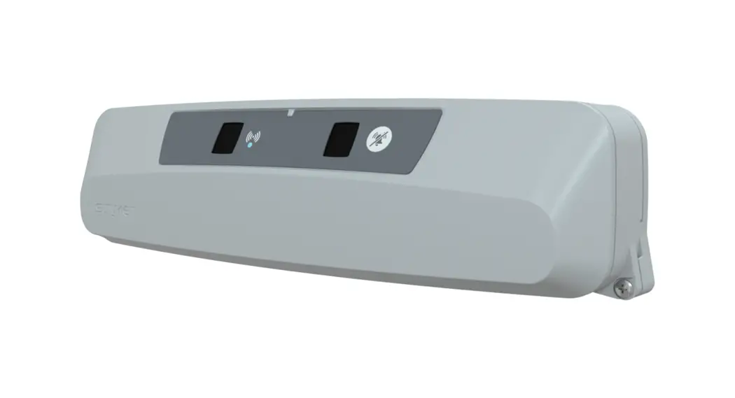
Product description
The Stryker Model 52 1200 3801 00 Secure® Connect”‘ is a cable-free nurse call solution. Secure Connect allows for patient nurse communication via the nurse call button, room controls, and TV controls without the need for any cables or wires.
Contraindications
None known.
Expected service life
The Secure Connect has a 10 year expected service life under normal use conditions and with appropriate periodic maintenance.
The battery has a two year expected service life under normal use conditions.
Disposal/recycle
Always follow the current local recommendations and/or regulations governing environmental protection and the risks associated with recycling or disposing of the equipment at the end of its useful life.
Specifications
| Overall length, width, and depth | 16.3 in. x 3.3 in. x 4.3 in. | 41.1 cm x 8.4 cm x 10.9 cm |
| Weight | 4 lb | 1.8 kg |
| System voltage rating | AC supply: 100-240 VAC, 50/60 Hz, 0.8A | |
| Secure Connect: 18 VDC, 1.67A | ||
| Wireless connection | Uses infrared (IR) LED and Bluetooth based on Stryker proprietary communication scheme Note — Minimum signal strength of the Secure Connect must be within 3dB of the connected product. Make sure the product is within 5.5 ft (1.7 m) of the SSeeccuurree CCoonnnneecctt. | |
Stryker reserves the right to change specifications without notice.
Specifications listed are approximate and may vary slightly from product to product or by power supply fluctuations.
| Environmental conditions | Operation | Storage and transportation |
| Ambient temperature | 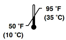 | 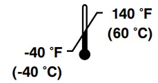 |
| Relative humidity (non-condensing) | 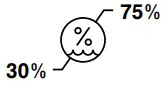 | 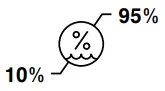 |
| Atmospheric pressure | 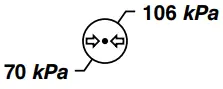 | 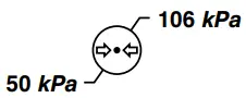 |
In accordance with the European REACH regulation and other environmental regulatory requirements, the components that contain declarable substances are listed.
| Description | Number | Substance of very high concern (SVHC) chemical name |
| Wallside room interface board | 521200380950 | Decamethylcyclopentasiloxane. dodecamethylcyclohexasiloxane, lead, octamethylcyclotetrasiloxane |
Bluetooth radio specifications
| Item | Specification – Chipset WT32i (Silicon Labs) | Unit | ||
| Channel | Min | Max | ||
| Operating frequencies | 79 | 2.4 | 2.4835 | GHz |
| Receiving bandwidth | Not applicable | 1 | MHz | |
| Maximum ERP | Not applicable | -24.148 | dBW | |
Contact information
Contact Stryker Customer Service or Technical Support at: 1-800-327-0770.
Stryker Medical 3800 E. Centre Avenue Portage, MI 49002 USA
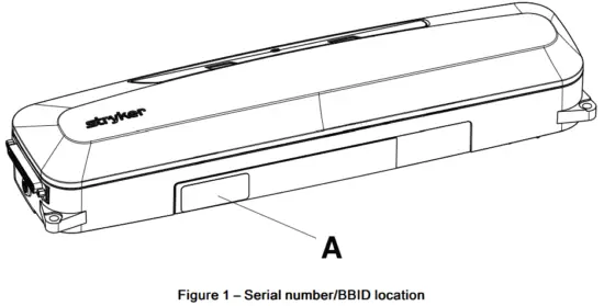
Note – The user and/or the patient should report any serious product-related incident to both the manufacturer and the Competent authority of the European Member State where the user and/or patient is established. To view your operations or maintenance manual online, see https://techweb.stryker.com/. Have the serial number (A) of your Stryker product available when calling Stryker Customer Service or Technical Support. Include the serial number in all written communication.
Serial number location
You can find the serial number (A) and bed bay identification number (BBID) on the bottom of the product (Figure 1).
Installation
Installing Secure Connect
Tools required:
- #2 Phillips screwdriver
- #1 Phillips screwdriver
- Straight pick
- Tape measure
- Level
- Pencil
- Tools required for hospital supplied fasteners
Procedure:
- Record the Secure Connect BBID (Serial number location (page 5)) and room number/patient position on the Secure Connect association form (page 22).
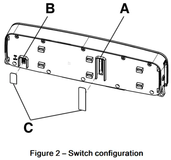
- Using a straight pick, configure the SB1 and SB2 dip-switches (A) to match the nurse call system and nurse call communication cable (Figure 2).
CAUTION – Always match the dip-switches on SB1 and SB2 to the connected product configuration to avoid the risk of head wall damage.
Note – To confirm dip-switch configuration, contact Stryker customer service or technical support (Contact information (page 5)).
- Using a straight pick, turn the Secure Connect ON/OFF switch (B) to the ON position (Figure 2).
- Install the two supplied IPX labels (C) over the dip-switch and the ON/OFF cutouts located on the back of the Secure Connect (Figure 2).
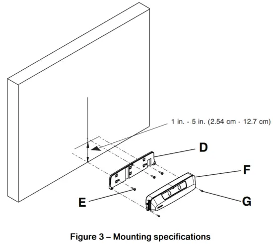
- Using a tape measure and pencil, mark the intended center of the bed location (vertical line) (Figure 3).

- Center the mounting plate on the vertical line made in step 5 and mount the bottom of the mounting plate max 1 in. (2.54 cm) off the floor (Figure 3).
Note
• Do not mount on a baseboard if the baseboard thickness exceeds 1 in. (2.54 cm).
• You may mount the bottom of the mounting plate up to 5 in. from the floor if you can always maintain a distance of at least 5 in. between the head end of the bed and the wall. Consider use of a floor threshold or roller bumpers. - Using a level on the bottom of the mounting plate (D), make sure that the bottom of the mounting plate (D) is level when you position the mounting plate (D) on the reference marks made in steps 5 and 6 (Figure 3).
- Use a pencil to mark the three screw holes of the mounting plate (D).
- Using the appropriate tool with the hospital supplied fasteners (E, not included), secure the mounting plate (D) to the wall (Figure 3).
- Attach the Secure Connect (F) to the mounting plate (D) (Figure 3).
- Using a #2 Phillips screwdriver, secure the Secure Connect (F) to the mounting plate (D) with the two supplied screws (700001126359) (G) (Figure 3).
- Plug the Secure Connect power supply into a hospital grade protective earthed wall outlet.
Note – Position the power supply in an accessible location. - On the Secure Connect, plug in the female end of the power supply.
- On the Secure Connect, plug in the nurse call communication cable.
- Using a #1 Phillips screwdriver, secure the nurse call communication cable to the Secure Connect.
- Connect and secure the nurse call communication cable to the nurse call system wall plug.
- Configure the Secure Connect, see Configuring the Secure Connect (page 11).
- Follow the procedure in the product manual to connect the product to the Secure Connect.
CAUTION – Always match the dip-switches of a product to the head wall configuration if a nurse call communication cable needs to be connected to avoid the risk of head wall damage.
Note
- If a Secure Connect is moved, repeat steps 1 and 10-17.
- If a product is moved to another configured Secure Connect, no change needs to be made as the product will connect automatically.
Installation checklist
Follow this checklist for the 521200380100 Secure Connect:
- Confirm that you do not have any unused components after installation. Your Secure Connect does not ship with any extra components
- Check that the Secure Connect ID number and room number/location has been recorded on the Secure Connect association form (page 22) Use a tape measure to check that the Secure Connect is installed at the horizontal center of the wall behind the bed location
- Use a tape measure to check that the bottom of the Secure Connect is installed 1 in. – 5 in. (2.54 cm – 12.7 cm) from the floor
- Use a level to confirm that the mounting plate is level
- All fasteners are tight with no signs of protruding or missing fasteners
- Power supply is plugged into a hospital grade protective earthed wall outlet and to the Secure Connect
- Nurse call communication cable is plugged into the Secure Connect and the nurse call system
| Product ID number: | |||
| Installed by: | Date: | ||
| Inspected by: | Date: | ||
Note – Maintain a copy of this record for at least 10 years.
Operation
Secure Connect indicators/functions
The Secure Connect has indicator symbols and a nurse call cord out cancel button (A) that is located on top of the product. This button cancels the alert if the nurse call communication cable is unplugged.
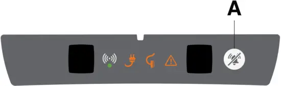
| Indicator | Indicator light | Status |
 | Solid | Connected |
| Pulse | Connecting |
 | Flash | Connection error |
 | Pulse | AC power unplugged |
| Flash | Low battery |
| Pulse | Nurse call communication cable unplugged | |
 | Solid | The Secure Connect is not configured |
| Flash | Error (reference product display for error detail) |
 | Flash | Battery error |
Configuring the Secure Connect Tools required:
- Secure Connect scanner (521200380700) (option) or Secure Connect compatible product
- Stryker service tool (521205080001) (option)
Note – Stryker service tool required if you use the Secure Connect scanner.
CAUTION – Always match the dip-switches on SB1 and SB2 to the product configuration to avoid the risk of head wall damage.
Procedure:
- Using the Secure Connect scanner:
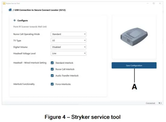
- Using the Stryker service tool, select the supplied soft configuration and settings.
- Select Save Configuration (A) (Figure 4).
- Using a ProCuity Th4 bed:
- Apply the brakes.
Note – See the Model 3009 ProCuity Operations Manual for steps to apply the brakes. - Confirm the Secure Connect connection to ProCuity.
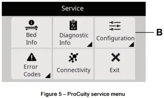
Note – The icon will appear on the ProCuity home screen when Secure Connect has connected. - Enter the service menu and select Configuration (B) (Figure 5).
Note – See the Model 3009 ProCuity Maintenance Manual for steps to access the service menu.
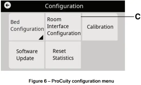
- In the configuration menu, select Room Interface Configuration (C) (Figure 6).

- Input the supplied settings and select Save.
Testing the Secure Connect
Tools required:
- Secure Connect scanner (521200380700) (option) or Secure Connect compatible product
- Stryker service tool (521205080001) (option) Note – Stryker service tool required if you use the Secure Connect scanner.
Procedure:
- Using the Secure Connect scanner:
- Using the Stryker service tool test function, activate the nurse call.
Using a ProCuity bed: - Using the footboard and siderail control panels, activate the nurse call.
Note – See the Model 3009 ProCuity Operations Manual for steps to activate nurse call.
Preventive maintenance
Remove product from service before you perform the preventive maintenance inspection. Check all items listed during annual preventive maintenance for all Stryker Medical products. You may need to perform preventive maintenance checks more often based on your level of product usage. Service only by qualified personnel.
Inspect the following items:
- All fasteners are secure
- The Secure Connect casing is not cracked or damaged
- Mounting plate not cracked or damaged
- The Secure Connect front label is not damaged
- Replace the battery (every two years)
Product serial number:
Completed by:
Date:
Cleaning
CAUTION
- Do not clean, disinfect, service, or perform maintenance while the product is in use.
- Always unplug the power cord from the wall outlet when large spills occur near the circuit boards and cables. Clean up the fluid, and inspect the product. Fluids can cause unpredictable operation and decreased functionality of any electrical product. Do not return the product to service until dry and tested for safe operation.
Recommended cleaning method:
- Using spray or pre-soaked wipes, hand wash all exposed surfaces of the product with a mild detergent.
- Follow the cleaning solution manufacturer’s instructions for appropriate contact time and rinse requirements.
- Dry the product before you return it to service.
Note – Avoid oversaturation. Do not allow the product to remain wet.
Disinfecting
CAUTION
- Do not clean, disinfect, service, or perform maintenance while the product is in use.
- Always unplug the power cord from the wall outlet when large spills occur near the circuit boards and cables. Clean up the fluid, and inspect the product. Fluids can cause unpredictable operation and decreased functionality of any electrical product. Do not return the product to service until dry and tested for safe operation.
- Always wipe down with clean water (or 70% isopropyl alcohol, if using Virex® TB) and dry each product after disinfecting. Some disinfectants are corrosive in nature and may cause damage to the product. If you do not rinse and dry the product, you may leave a corrosive residue on the surface of the product. This corrosive residue could cause premature degradation of critical components. Failure to follow these disinfecting instructions may void your warranty.
Recommended disinfectants for this product’s surfaces include:
- Quaternary (active ingredient – ammonium chloride)
- Phenolic (active ingredient – o-phenylphenol)
- Chlorinated bleach solution (10,000 ppm available chlorine, 941 mL of a 5.25% sodium hypochlorite solution per 4000 mL of water)
- Alcohol (active ingredient – 70% isopropyl alcohol)
- Accelerated hydrogen peroxide (5,000 ppm hydrogen peroxide)
Disinfection method:
- Follow the disinfectant solution manufacturer’s dilution recommendations.
- Using spray or pre-soaked wipes, apply the recommended disinfectant solution.
- Hand wash all exposed surfaces of the product with the recommended disinfectant.
- Dry the product before you return it to service.
Note
- Avoid oversaturation. Do not allow the product to remain wet.
- Follow the manufacturer’s dilution recommendations for appropriate contact time and rinse requirements. Follow the chemical manufacturer’s guidelines to disinfect.
Wirreless notifications
For product equipped with wireless communication technology, these statements apply to the countries as indicated:
| Country | Notiffication |
| Canada | Contains IC: 5123A-BGTWT32I This device complies with Innovation, Science and Economic Development Canada’s licenseexempt RSSs. Operation is subject to the following two conditions: (1) this device may not cause interference, and (2) this device must accept any interference, including interference that may cause undesired operation of the device. |
| Mexico | |
| Oman |  |
| Singapore |  |
| South Africa |  |
| Thailand |
|
| United States | Contains FCC ID: QOQWT32I This device complies with Part 15 of the FCC Rules. Operation is subject to the following two conditions: (1) this device may not cause harmful interference, and (2) this device must accept any interference received, including interference that may cause undesired operation. Changes or modifications not expressly approved by the party responsible for compliance could void the user’s authority to operate the equipment. |


EMC information
WARNING
- Portable RF communications equipment, including peripherals such as antenna cables and external antennas, should be no closer than 12 inches (30 cm) to any part of the Secure Connect locator, including cables specified by the manufacturer.
- Avoid stacking or placing equipment adjacent with other equipment to prevent improper operation of the product. If such use is necessary, carefully observe stacked or adjacent equipment to make sure that they operate properly.
- The use of accessories, transducers, and cables, other than those specified or provided by the manufacturer, could result in increased electromagnetic emissions or decreased electromagnetic immunity and result in improper operation.
The 521200380100 Secure Connect locator was evaluated using the following cables:
| Cable | Length (m) |
| AC mains input cable | 1.2 |
| Nurse call (DB-37) | 2.4 |
| Guidance and manufacturer’s declaration – electromagnetic emissions | ||
| The 521200380100 Secure Connect locator is intended for use in the electromagnetic environment specified below. The customer or the user of the 521200380100 Secure Connect locator should assure that it is used in such an environment. | ||
| Emissions test | Compliance | Electromagnetic environment |
| RF Emissions CISPR 11 | Group 1 | Note – The emissions characteristics of this equipment make it suitable for use in industrial areas and hospitals (CISPR 11 class A). If it is used in a residential environment (for which CISPR 11 class B is normally required) this equipment might not offer adequate protection to radio-frequency communication services. The user might need to take mitigation measures, such as relocating or re-orienting the equipment. |
| RF Emissions CISPR 11 | Class A | |
| Harmonic Emissions IEC 61000-3-2 | Class A | |
| Voltage Fluctuations Flicker Emissions IEC 61000-3-3 | Complies | |
| Surge IEC 61000-4-5 | ±0.5 kV, ±1 kV lines to lines ±0.5 kV, VI kV, ±2 kV lines to earth | ±0.5 kV, ±1 kV lines to lines ±0.5 kV, VI kV, ±2 kV lines to earth | Main power quality should be that of a typical commercial or hospital environment. |
| Voltage dips, voltage variations and short interruptions on power supply input lines IEC 610004-11 | 0%UT for 0.5 cycle at 0°, 45°, 90°, 135°, 180°, 225°, 270°, and 315° 0%UT for 1 cycle 70%UT (30% dip in UT) for 25/30 cycles 0% UT for 250/300 cycles | 0%UT for 0.5 cycle at 0°, 45°, 90°, 135°, 180°, 225°, 270°, and 315° 0%UT for 1 cycle 70%UT (30% dip in UT) for 25/30 cycles 0% UT for 250/300 cycles | Main power quality should be that of a typical commercial or hospital environment. If the user of the 521200380100 Secure Connect locator requires continued operation during power main interruptions, it is recommended that the device be powered from an uninterrupted power supply or a battery. |
| Power frequency (50/60 Hz) magnetic field IEC 61000 4 8 | 30 A/m | 30 A/m | Power frequency magnetic fields should be at levelscharacteristic of a typical location in a typical commercial or hospital environment. |
| Note – UT is the a.c. mains voltage before applications of the test level. | |||
| Guidance and manufacturer’s declaration – electromagnetic immunity | |||
| The 521200380100 Secure Connect locator is suitable for use in a professional healthcare facility environment and not in environments exceeding immunity test conditions that the product was evaluated to, such as near high frequency (HF) surgical equipment and inside of the radio frequency (RF) shielded room of magnetic resonance imaging (MRI) equipment. The customer or the user of the 521200380100 Secure Connect locator should assure that it is used in such an environment and that the electromagnetic environment guidance listed below is followed. | |||
| Immunity test | IEC 60601 test level | Compliance level | Electromagnetic environment-gui Electromagnetdance |
| Electrostatic Discharge (ESD) IEC 61000-4-2 | ±8 kV contact ±15 kV air | ±8 kV contact ±15 kV air | Floors should be wood, concrete, or ceramic tile. If floors are covered with synthetic material, the relative humidity should be at least 30%. |
| Electrostatic fast transient/ burst IEC 61000 4 4 | ±2 kV for power supply lines ±1 kV for input/output lines | ±2 kV for power supply lines ±1 kV for input/output lines | Main power quality should be that of a typical commercial or hospital environment. |
| Recommended separation distances between portable and mobile RF communication equipment and the 521200380100 Secure Connect locator | |||
| The 521200380100 Secure Connect locator is intended for use in an electromagnetic environment in which radiated RF disturbances are controlled. The customer or the user of the 521200380100 Secure Connect locator can help prevent electromagnetic interferences by maintaining a minimum distance between portable and mobile RF communications equipment (transmitters) and the 521200380100 Secure Connect locator, including cables, as recommended below, according to the maximum output power of the communications equipment. | |||
| Band (MHz) | Service | Maximum power (W) | Minimum separation distance (m) |
| 380-390 | TETRA 400 | 2. | 0.3 |
| 430-470 | GMRS 460; FRS 460 | 2.0 | 0.3 |
| 704-787 | LTE Band 13, 17 | 0.2 | 0.3 |
| 800-960 | GSM 800/900; TETRA 800; iDEN 820; CDMA 850; LTE Band 5 | 2.0 | 0.3 |
| 1,700-1,990 | GSM 1800; CDMA 1900; GSM 1900; DECT; LTE Band 1, 3, 4, 25; UMTS | 2.0 | 0.3 |
| 2,400-2,570 | Bluetooth; WLAN; 802.11 b/g/n; RFID 2450; LTE Band 7 | 2.0 | 0.3 |
| 5,100-5,800 | WLAN 802.11 a/n | 0.2 | 0.3 |
| For transmitters rated at a maximum output power not listed above, the recommended separation distance d in meters (m) can be estimated using the equation applicable to he frequency of the transmitter, where P is the maximum output power rating of the transmitter in watts (W) according to the transmitter manufacturer. Note – These guidelines may not apply in all situations. Electromagnetic propagation is affected by absorption and reflection from structures, objects and people. | |||
| Conducted RF IEC 61000- 4-6 Radiated RF IEC 61000-4-3 | 3 Vrms 150 kHz to 80 MHz 3 V/m 80 MHz to 2.7 GHz | 3 Vrms 3 V/m | Portable and mobile RF communications equipment should follow the guidance in the table titled “Recommended separation distances between portable and mobile RF communication equipment and the 521200380100 Secure Connect locator.” If the mobile service is not listed in the table, the recommended separation distance should be calculated from the equation appropriate for the frequency of the transmitter. Recommended separation distance D=(2) (√P ) where P is the maximum output power rating of the transmitter in watts (W) according to the transmitter manufacturer and d is the recommended separation distance in meters (m). Field strengths from fixed RF transmitters, as determined by an electromagnetic site surveya , should be less than the compliance level in each frequency rangeb. Interference may occur in the vicinity of equipment marked with the following symbol: |
Secure Connect associatiom form
| Secure Connect BBID | Room numbar/Location |
Note — Give this form to your Stryker representative or your IT system analyst so they can create the associations on the server.
5212-009-211 Rev AA.1
Stryker Medical
3800 E. Centre Avenue
Portage, MI 49002
USA
5212-009-211 Rev AA.1
WCR: AA.5
2021-12


