DIGITAL WATCHDOG DWC-MV95WiATW Vandal Dome IP Camera
WHAT’S IN THE BOX
Quick setup and Installation Guides |  | 1 set | Tapping Screws PA 4×25 – 4pcs | 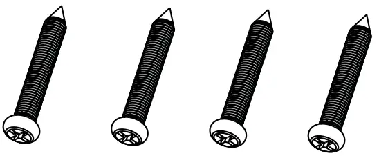 | 1 set |
Mounting Template | 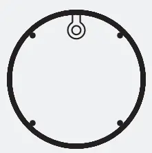 | 1 | Plastic Plugs – 4pcs | 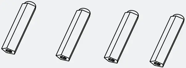 | 1 set |
Waterproof Cap |  | 1 set | Rubber Plug |  | 1 |
Hexagonal Wrench 0.11” (3mm) | 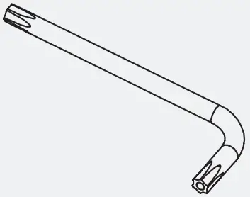 | 1 | 2nd CVBS Local Testing Output and DC12V Input | 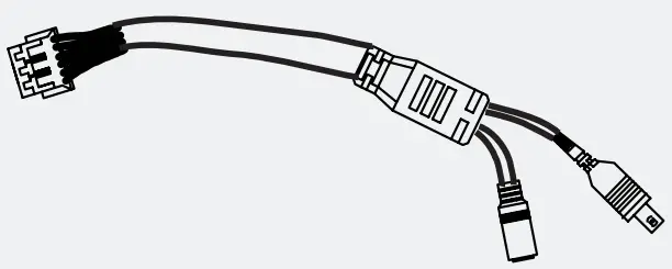 | 1 set |
NOTE: Download all your support materials and tools in one place
- Go to: http://www.digital-watchdog.com/resources
- Search your product by entering the part number in the ‘Search by Product’ search bar. Results for applicable part numbers will populate automatically based on the part number you enter.
- Click ‘Search’. All supported materials, including manuals and quick start guide (QSGs) will appear in the results.


Attention: This document is intended to serve as a quick reference for initial set-up. It is recommended that the user read the entire instruction manual for complete and proper installation and usage.
STEP 1 – PREPARING TO MOUNT THE CAMERA
- The mounting surface must bear five times the weight of your camera.
- Do not let the cables get caught in improper places or the electric line cover to be damaged. This may cause a breakdown or fire.
- For the installation process, remove the dome cover from the camera base using the included wrench.
- Using the mounting template sheet or the camera itself, mark and drill the necessary holes in the wall or ceiling.
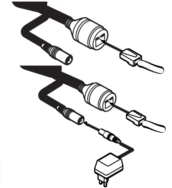
STEP 2 – POWERING THE CAMERA
Pass the wires through and make all the necessary connections. See STEP 4 for more information.
- NETWORK CONNECTIONS – Using a PoE Switch or PoE Injector, connect the camera using an Ethernet cable for both data and power.
- NETWORK CONNECTIONS – Not using PoE Switch or PoE Injector, connect the camera to the switch using an Ethernet cable for data transmission and use a power adapter to power the camera.
Power requirements | Power consumption |
| DC12V, PoE (IEEE 802.3af class 3). Adapter not Included. | <9W |
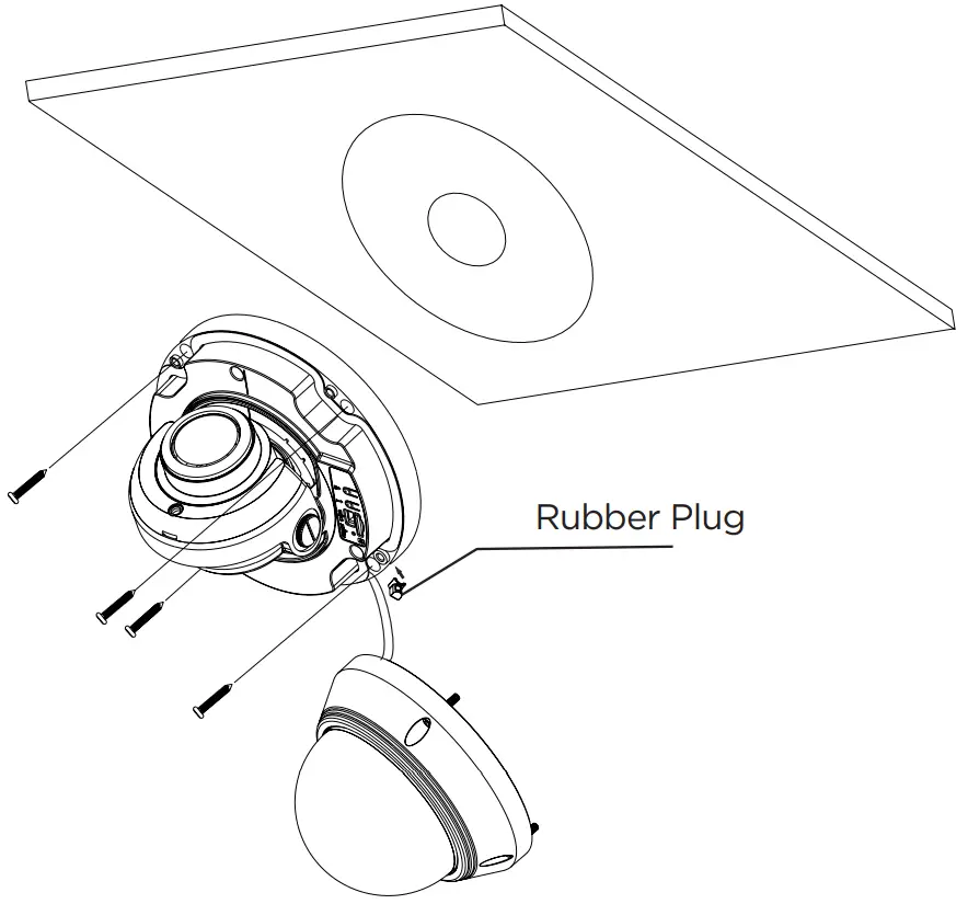
STEP 3 – INSTALLING THE CAMERA
- Mount the camera to the mounting surface using the included screws and anchors.
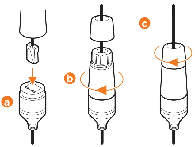
- To use the camera’s waterproof wiring:
a. Install the LAN cable into . b. will be assembled to with a 1/4 turn. c. Thread tightly to .
- Adjust the camera’s tilt and angle. a. Pan and rotation: 0 ~ 345° b. Tilt: 0 ~ 77°
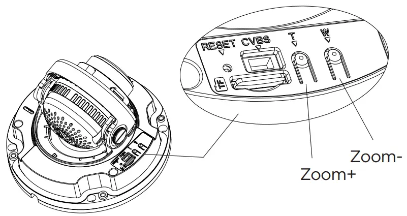
- Adjust the camera’s zoom using the T and W buttons at the base of the camera.

- Place the dome cover on the camera using the wrench to tighten the screws on the dome.

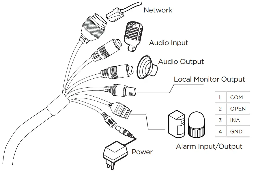
STEP 4 – CABLING
Use the diagram below to properly connect power, network, alarm input and outputs and audio to the camera.
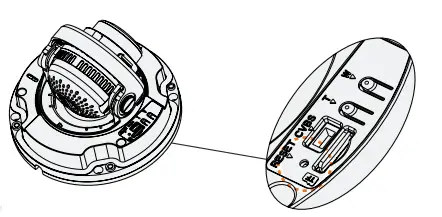
STEP 5 – MANAGING THE SD CARD
- To install the camera’s SD Card, locate the SD card slot at the base of the camera module.
- Insert a class 10 SD/SDHC/SDXC card into the SD card slot by pressing the SD card until clicks.
- To remove the SD card, press the card inward until it clicks to release it from the card slot.

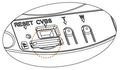
Resetting the camera: To reset the camera, use the tip of a paper clip or a pencil and press the reset button at the base of the camera. Pressing the button for five (5) seconds will initiate a camera-wide reset of all the settings, including network settings.
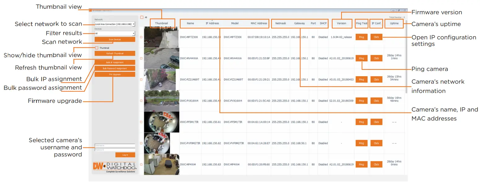
STEP 6 – DW® IP FINDER™
Use the DW® IP Finder™ software to scan the network and detect all® cameras, set the camera’s network settings or access the camera’s web client.
Network Setup
- To install the DW IP Finder, go to: http://www.digital-watchdog.com
- Enter “DW IP Finder” on the search box at the top of the page.
- Go to the “Software” tab on the DW IP Finder page to download the installation file.
- Follow the installation to install the DW IP Finder. Open the DW IP Finder and click ‘Scan Devices’. It will scan the selected network for all supported devices and list the results in the table. During the scan, the DW® logo will turn gray.
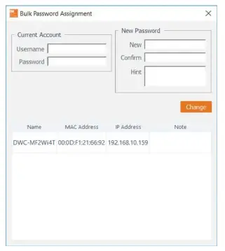
- When connecting to the camera for the first time, a password must be set. To set up a password for your camera:
a. Check the box next to the camera in the IP Finder’s search results. You can select multiple cameras. b. Click “Bulk Password Assign” on the left. c. Enter admin/admin for the current username and password. Enter a new username and password to the right. Passwords must have a minimum of 8 characters with at least 4 combinations of uppercase letters, lowercase letters, numbers and special characters. Passwords cannot contain the user ID. d. Click “change” to apply all changes. - Select a camera from the list by double-clicking on the camera’s image or clicking on the ‘Click’ button under the IP Conf. column. The pop-up window will show the camera’s current network settings, allowing admin users to adjust the settings as needed.
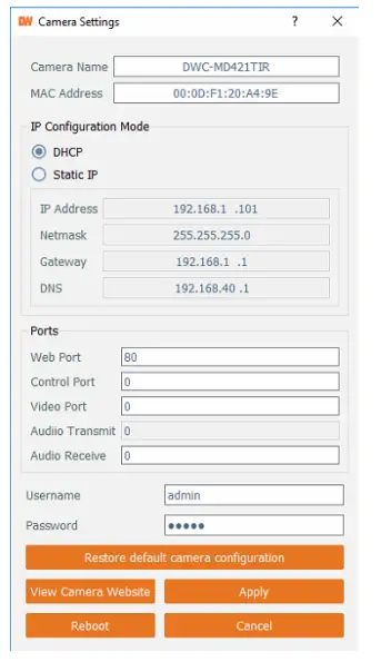
- To access the camera’s web page, click on the ‘View Camera Website’ from the IP Config window.
- To save changes made to the camera’s setting, enter the username and password of the camera’s admin account and click ‘Apply’.

Select DHCP to allow the camera to receive its IP address automatically from the DHCP server. Select “Static” to manually enter the camera’s IP address, (Sub)Netmask, Gateway and DNS information. The camera’s IP must be set to static if connecting to Spectrum® IPVMS. Contact your network administrator for more information.
![]() Default TCP/IP information: DHCP.
Default TCP/IP information: DHCP.
![]() Port forwarding must be set in your network’s router to access the camera from an external network.
Port forwarding must be set in your network’s router to access the camera from an external network.
STEP 7 – WEB VIEWER
NOTE: This camera’s web client is available via Internet Explorer® only.
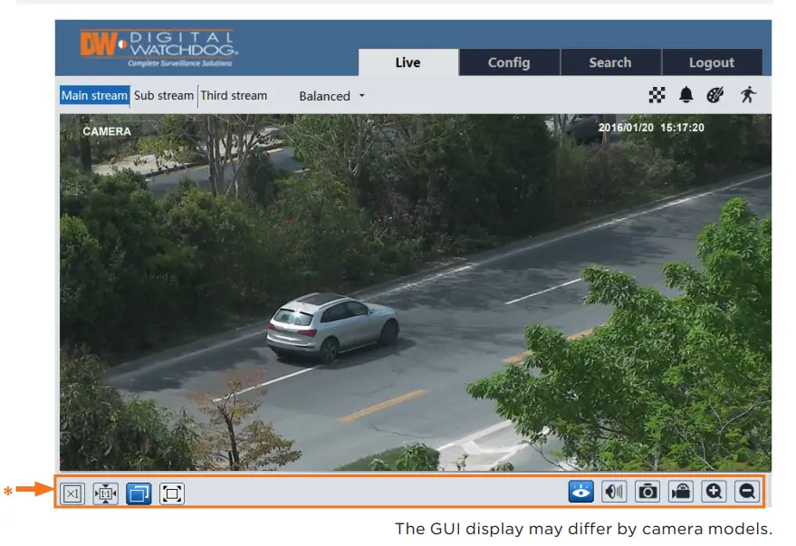
Once the camera’s network settings have been setup properly, you can access the camera’s web viewer. To open the camera using the DW IP Finder:
- Find the camera using the DW IP Finder.
- Double-click on the camera’s view in the results table.
- Press the ‘View Camera Website’. The camera’s web viewer will open up in your default web browser.
- Enter the camera’s username and password.
To open the camera using the web browser:
- Open a web browser (Internet Explorer® 8.0 or above).
- Enter the camera’s IP address and port in the address bar. Example: : http://<ipaddress>:<port>.
Port forwarding may be necessary to access the camera from a different network. Contact your network administrator for more information. 3. Enter the camera’s username and password (default admin/admin).
If you are accessing the camera for the first time, install the ActiveX player for web files to view video from the camera.
NOTE: Some menu options may not be available based on the camera model. See the full manual for more information.
Tel: +1 (866) 446-3595 / (813) 888-9555
Technical Support Hours:
9:00 AM – 8:00 PM EST, Monday through Friday
digital-watchdog.com