![]() Weather Station
Weather Station
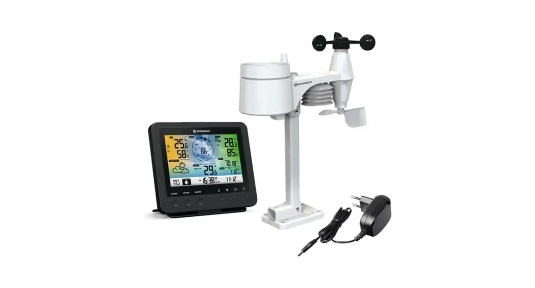
WI-FI Colour Weather Station + 5in1 Multisensor
Instruction manual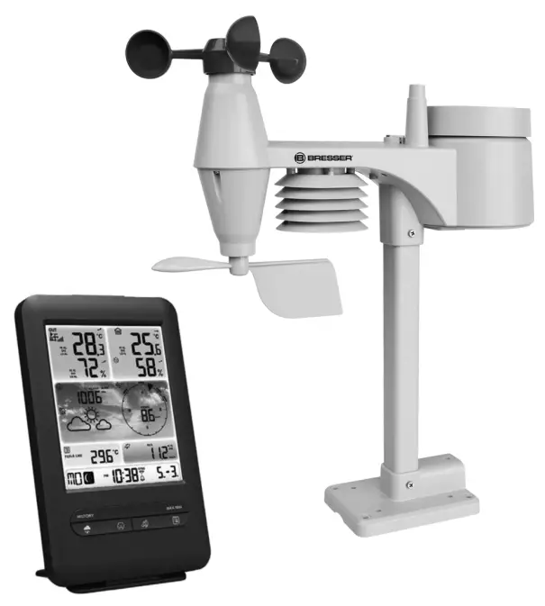 Visit our website via the following QR Code or web link to find further information on this product or the available translations of these instructions.
 www.bresser.de/P7002585
![]() GARANTIE · WARRANTY
GARANTIE · WARRANTY www.bresser.de/warranty_terms
![]()
APP DOWNLOAD: Weather Underground is a registered trademark of The Weather Channel, LLC. both in the United States and internationally. The Weather Underground Logo is a trademark of Weather Underground, LLC. Find out more about Weather Underground at www.wunderground.com
Apple and the Apple logo are trademarks of Apple Inc., registered in the U.S. and other countries. App Store is a service mark of Apple Inc.,
registered in the U.S. and other countries. Google Play and the Google Play logo are trademarks of Google Inc.
Imprint (German)
Bresser GmbH
Gutenbergstr. 2
46414 Rhede
Germany
http://www.bresser.de
For any warranty claims or service inquiries, please refer to the information on “Warranty” and “Service” in this documentation. We apologize for any inconvenience caused by the fact that we cannot process inquiries or submissions sent directly to the manufacturer’s address. Errors and technical changes excepted. © 2021 Bresser GmbH All rights reserved. The reproduction of this documentation – even in extracts – in any form (e.g. photocopy, print, etc.) as well as the use and distribution by means of electronic systems (e.g. image file, website, etc.) without prior written permission of the manufacturer is prohibited. The designations and brand names of the respective companies used in this documentation are generally protected by trade,
trademark and/or patent law in Germany, the European Union, and/or other countries.
Validity note
This documentation is valid for the products with the following article numbers: 7002585
Manual version:
0321 Manual designations: Manual_7002585_WIFI-Colour-Weather-Station_en-de_BRESSER_v032021a Always provide information when requesting service.
Features
- Measurement of Rainfall
- Measurement of wind speed
- Measurement of wind direction
- Internet time synchronization via PC
- Alarm with snooze function
- Outdoor temperature alarm (frost warning)
- Outdoor temperature (in °C or °F)
- Indoor temperature (in °C or °F)
- Humidity indoor/outdoor
- Barometric pressure
- Since function to display the total rainfall from a customized point in time.
- The highest and lowest value display
- maximum/Minimum value memory
- Colour display
- Backlight
About this Instruction Manual
![]() NOTICE
NOTICE
These operating instructions are to be considered a component of the device.
Read the safety instructions and the operating manual carefully before using this device. Keep this instruction manual in a safe place for future reference. When the device is sold or given to someone else, the instruction manual must be provided to the new owner/user of the product.
Parts overview Base station
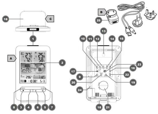
Illustration 1: All parts of the base station
- ALARM/SNOOZE button (snooze function or interrupt alarm)
- Colour display
- RAIN button (display of different precipitation values)
- BARO button (display of different air pres
- INDEX button (display change between felt temperature, dew point, heat index, and wind chill factor)
- WIND button (display change between average and current wind gust)
- MAX/MIN button (display change between maximum, minimum, or current value) HISTORY button (show measured values of the last 24 hours)
- CHANNEL button (channel selection)
- CLOCK SET button (setting the time manually)
- ALARM button (alarm setting)
- ALERT button (e.g. set temperature alarm)
- Wall mounting holder
- DOWN button (Value setting downwards)
- UP button (Value setting upwards)
- RESET button (reset all settings)
- HI/LO/AUTO slider (set or turn off backlight)
- Stand, removable
- REFRESH button (manual data update)
- SENSOR/WI-FI button (start manual sensor search or enable/disable WI-FI)
- Battery compartment (cover)
- BARO UNIT button (changes air pressure unit)
- °C/°F slider (display changes between °C and °F)
- Power jack
- USB power adapters with plug adapters and power cable (USB/hollow plug)
- USB power adapter with plug adapters and power cable (USB/hollow plug)
Parts overview Multisensor
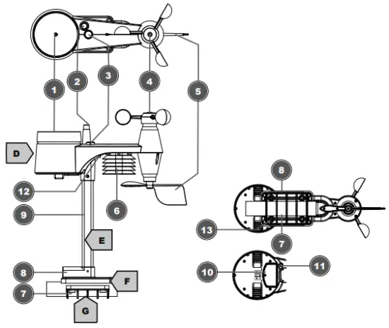
Illustration 2: All parts of the multisensor
- Rain gauge
- Antenna
- Circular level
- Wind cups (wind speed)
- wind vane (wind direction)
- Thermo-Hygrometer
- Pipe clamp
- Mounting shoe
- Mounting bar
- Battery compartment (cover)
- RESET button
- LED function indicator
- Mounting screws with nuts
Scope of delivery
The base station (A), power adapter (B), stand (C), multifunctional outdoor sensor (D), mounting rod (E), mounting shoe (F), pipe clamp (G), screws, 2 pc. CR2032 type battery (base unit), instruction manual
Also required (not included in delivery):
3 x 1.5V batteries type AA/LR6 (outdoor sensor)
Screen display
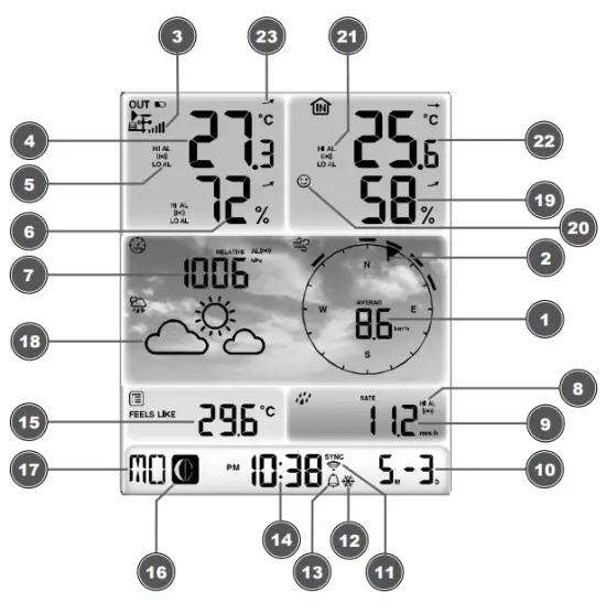
Illustration 3: Screen display
- Wind speed
- Wind direction
- Signal strength for outdoor sensor
- Outdoor temperature
- Outdoor temperature alarm enabled (HI/LO)
- Outdoor humidity
- Barometric pressure
- Precipitation alarm enabled (HI/LO)
- Precipitation amount
- Date
- WIFI synchronization
- Ice alert enabled
- Wake-up alarm enabled
- Current time
- Temperature felt
- Moon phase
- Weekday
- Graphical weather trend display
- Indoor humidity
- Comfort indicator (climate)
- Indoor temperature alarm enabled
- Indoor temperature
- Trend arrow (rising, constant, or falling)
Before commissioning
NOTICE
Avoid connection faults!
In order to avoid connection problems between the devices, the following points must be observed during commissioning.
- Place the base unit (receiver) and sensor (transmitter) as close together as possible.
- Connect the power supply to the base unit and wait until the indoor temperature is displayed.
- Establish a power supply for the sensor.
- Set up/operate the base unit and sensor within the effective transmission range.
- Make sure that the base unit and the radio sensor are set to the same channel.
When changing the batteries, always remove the batteries in both the base unit and the sensor and reinsert them in the correct order so that the radio connection can be re-established. If one of the two devices is operated via a mains power connection, the power connection for this device must also be disconnected briefly when changing the battery. If, for example, only the batteries in the sensor are replaced, the signal cannot be received or can no longer be received correctly.
Note that the actual range depends on the building materials used in the building and the position of the base unit and outdoor sensor. External influences (various radio transmitters and other sources of interference) can greatly reduce the possible range. In such cases, we recommend finding other locations for both the base unit and the outdoor sensor. Sometimes a shift of just a few centimeters is enough!
The first steps
Follow the bullet points in order, to ensure a successful setup.
- Setting up power supply (base station and wireless sensor)
- Mount the wireless sensor
- The base station is now in AP mode (LED flashes green) and ready for initial setup.
- Create an account with a weather service provider compatible with your station, e.g. wunderground.com or weathercloud.net and add the station to your account (“My Profile” / “Add Weather station”) or (“Devices” / “+ New”). Make a note of the station ID and password, as they will be needed in the next step. Write down the Station ID and Password, because they are needed in the next step.
- Setting up the base station (Establish WIFI / Router connection)
- Viewing weather data via the web, mobile or tablet
Setting up power supply
IMPORTANT: When inserting the batteries, always ensure that the battery poles are correctly aligned (+/-)!
Base unit
- Slide the appropriate plug adapter onto the spigot on the mounting plate of the USB power adapter until it clicks into place.
- Insert the barrel connector of the power cable into the connection socket on the base unit.
- Insert the USB plug of the power cord into the power adapter.
- Insert the mains plug of the main adapter into the socket.
- The device is powered on directly.
Installing the backup battery: - Remove the battery compartment cover.
- Insert the battery into the battery compartment.
- Replace the battery compartment cover.
Wireless sensor - Remove the screw on the battery compartment cover with a suitable Phillips screwdriver and remove the battery compartment cover.
- Insert the batteries into the battery compartment.
- Replace and screw on the battery compartment cover.
Attaching rubber linings
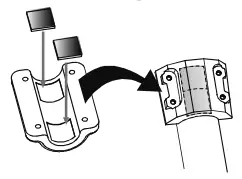
Attach the supplied self-adhesive rubber pads to the clamps as shown to ensure a firmer fitting of the mounting rod.
Assembling and installing the multifunctional remote sensor
Depending on the desired location, the remote sensor can be installed in two different ways.
NOTICE! During the assembly make sure that the upper part of the wind vane is a minimum of 1.5 meters off the ground. Use the circular level in the sensor head to ensure a level installation. The windmill must point to the North.
Assembly on a vertical or horizontal wooden element
- Slide one end of the assembly bar into the aperture below the sensor head.
- Slide one screw through the borehole and put it on the nut on the opposite side. Tighten the screw connection by hand.
- Depending on the desired orientation, slide the opposite end of the assembly bar into the aperture for vertical or horizontal mounting of the assembly base.
- Slide another screw through the borehole of the assembly base and put it on the nut on the opposite side. Tighten the screw connection by hand.
- Place the assembly base with its bottom site first on a wooden element. Use 4 wood screws to tighten it.
Assembly on a vertical or horizontal tube - Repeat steps 1 to 4 as before.
- Place the assembly base with its bottom site first on the tube. Push the tube bracket against the tube from the opposite side.
- Slide 4 screws through the boreholes of the assembly base and through the boreholes of the tube bracket on the other side.
- Put on the 4 nuts and tighten the screw connection by hand.
Signal transmission
The base station automatically connects to the multi outdoor sensor and (if available) to other wireless sensors. You can also press the WIFI / SENSOR button to search directly for the sensors. If the connection is successful, the outdoor symbol (OUT) and/or the channel will appear on the display.
Connection status display:
| Connection status | Display indication |
| Good signal | Receiver symbol |
| The sensor is searched for | Receiver symbol flashes |
| No signal for 48 hours | Er’ (Error) is displayed |
| Sensor battery low, good signal | The battery symbol is displayed |
Create a user account for Weather
Underground (optional)
- Enter the following web address for the ‘Weather Underground’ service in the address bar of your web browser: https://www.wunderground.com
- Click on ‘Join’ to get to the registration page.
- Enter your personal user data and click on ‘Sign up.
- Follow the further setup steps.
- Under the menu item ‘Sensor Network’ > ‘Connect a Weather Station’ your own weather station can be added.
- A ‘Station ID’ and a ‘Station Key/Password’ are automatically generated by the service, which is needed for the following configuration of the weather station.
NOTICE! Use a valid e-mail address for registration. Otherwise, the service can not be used.
Create a user account for weather cloud (optional)
- Enter the following web address in the address bar of the web browser: https://weathercloud.net
- Under ‘Join us today’ enter the personal user data and click on ‘Sign up.
- After successful registration and verification of the e-mail address, select the menu item “Devices” under the user account.
- Click the ‘+New’ link under ‘Devices’ and enter the device and location data in the ‘Create New
Device window to create a new device. Select the appropriate weather station under ‘Model’. For ‘Link type’ select the option ‘Pro Weather Link’. - A ‘weather cloud ID’ and a ‘key’ which are needed for the following configuration of the weather station are automatically generated by the service. These can be reached via the account at weathercloud.net under Devices > Settings > Link.
NOTICE! Use a valid e-mail address for registration. Otherwise, the service can not be used.
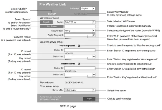
Configuration / Setting up a WI-FI connection
- If the base station has not yet been connected to a router, it will switch to AP (Access Point Mode) mode after the first power supply. The display will show ‘AP’ and the symbol for WI-FI synchronization.
- Use a smartphone, tablet, or computer to connect to Wi-Fi.
NOTICE! The respective device itself must also be equipped with a WI-FI function. - In the system settings of the device, switch to W-LAN or WI-FI settings and select the wireless network (SSID) named ‘PWS-XXXXXX’.
- After successful connection via the address bar of the web browser, enter the IP address ‘http://192.168.1.1‘ to establish a connection to the settings menu of the weather station.
NOTICE! Always prepend ‘http://’ to the IP address to avoid browser-dependent connection errors. Recommended browsers: the latest version of Chrome, Safari, Edge, Firefox, or Opera. - Make the following settings in the settings menu:
 *Leave the field blank if registration is not yet available and entries are to be made later.
**Manual setup requires additional router information (including e.g. IP address, SSID, etc) - After completing the settings, the device will recognize the default WI-FI connection after each restart.
- In Access Point Mode, the WI-FI / SENSOR button can be pressed for 6 seconds to restore the previous settings.WI-FI connection status:
 *Leave the field blank if registration is not yet available and entries are to be made later.
| WI-FI symbol is shown in the display Connection to the WI-FI router successful | WI-FI symbol flashes in the display The connection to the WI-FI router is not stable or ongoing connection | AP symbol flashes in the display Access Point Mode enabled |
Automatic time setting
After the power supply and the Wi-Fi connection are established, the time and date information is automatically transmitted by the Internet time server.
If the time/date information is received correctly, the date and time are set automatically and the reception symbol is displayed.
If the time/date information was not received or not received correctly, proceed as follows:
- In countries/regions whose time zone differs from the coordinated world time UTC, the time zone must be set manually (see chapter ‘Setting the time zone’) in order to display the correct time.
- Press the REFRESH button on the base unit for about 2 seconds to re-initiate the retrieval of Internet time information.
- Check the W-LAN settings on the base unit for the correctness and correct them if necessary so that an Internet connection can be established (see chapter ‘Establishing a W-LAN connection’).
Manual time setting
To set the time/date manually, first, disable the reception of the time signal by pressing the RCC button for approx. 8 seconds.
- Press and hold the CLOCK SET button for approx. 3 seconds to change to time setting mode.
- Digits to be set are flashing.
- Press the UP or DOWN button to change the value.
- Press the CLOCK SET button to confirm and continue to the next setting.
- Settings order: time offset > daylight saving time on/off > hours > minutes > 12/24 hours mode > year > month > day > day/month display change > time synchronization on/off > languag
NOTICE! When time is set manually, the time synchronization must be deactivated. - Finally, press the CLOCK SET button to save the settings and exit the setting mode.
NOTICE! In normal display mode, press the CLOCK SET button to switch between the year display and date display. In setting mode, press the CLOCK SET button for about 2 seconds to return to the normal display mode.
Time zone setting
To set a different time zone, proceed as follows:
- Press and hold the CLOCK SET button for approx. 3 seconds to change to time setting mode. The current value for the time offset flashes.
- Press the up or the DOWN button to set the desired hour value (0 to 10 hours) for the time offset.
- Finally, press the CLOCK SET button for approx. 3 seconds to save the settings and exit the setting mode.
Manual measurement display
- Press MAX/MIN button several times to display the stored values one after another.
- Display order: Current values > MAX (highest values) > MIN (lowest values)
- When highest or lowest values are displayed, press and hold the MAX/MIN button for approx. 3 seconds to switch the temperature unit display from °C to °F or reverse.
Technical data
Base unit
| Power supply: | DC 5V 1A power plug Type: HX075-0501000-AX |
| Maximum number of sensors | 1x wireless multisensor 1x wireless internal sensor (optional) |
| Temperature measuring range | -5°C to 50°C |
| Dimensions | 79 x 157 x 41 mm (W x H x D) |
| Weight | 130 g |
Multisensor
| Batteries | 3x AA, 1.5V |
| RF transmission frequency | 868Mhz |
| RF Transmission range | 150 m |
| Maximum radio-frequency power | < 25mW |
| Temperature measuring range | -40°C to 60°C (-40°F to 140°F) |
| Barometer measuring range | 540 to 1100hPa (relative range: 930 to 1050hPa) |
| Humidity measuring range | 1% to 99% |
| Humidity measuring range | 1% HR |
| Precipitation measuring range | 0 to 19999 mm (0 to 787.3 inches) |
| Wind speed measuring range | 0 to 112 mph, 50 m/s, 180km/h, 97 knots |
| Dimensions | 392.2 x 326 x 144.5 mm (W x H x D) |
| Weight | 1096g |
SPECIFICATIONS
| Wi-Fi standard | 802.11 b/g/n |
| Wi-fi operating frequency : | 2.4 GHz |
| Supported devices | Smart device with built-in Wi-Fi AP mode (Access Point) function, PC or notebook, Android or iOS smartphone/tablet |
| Supported internet browsers | Internet browsers that support HTML 5 |
EC declaration of conformity
Hereby Bresser GmbH declares that the radio equipment type with 7002585 complies with Directive 2014/53/EU. The full text of the EC declaration of conformity is available at the following Internet address www.bresser.de/download/7002585/CE/7002585_CE.pdf
UKCA Declaration of Conformity
 Bresser GmbH has issued a “Declaration of Conformity” in accordance with applicable guidelines and corresponding standards. The full text of the UKCA declaration of conformity is available at the following internet address: www.bresser.de/download/7002585/ UKCA/7002585_UKCA.pdf
Bresser UK Ltd. • Suite 3G, Eden House, Enterprise Way, Edenbridge, Kent TN8 6Hf, Great Britain
Disposal
 Dispose of the packaging materials properly, according to their types, such as paper or cardboard. Contact your local waste disposal service or environmental authority for information on the proper disposal.
 Do not dispose of electronic devices in the household garbage!
According to the European Directive 2012/19/EU on Waste Electrical and Electronic Equipment and its transposition into national law, used electrical equipment must be collected separately and recycled in an environmentally sound manner.
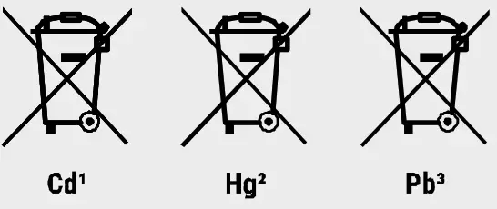
![]() Batteries and rechargeable batteries must not be disposed of with household waste. You are legally obliged to return used batteries and accumulators and can return the batteries after use either in our sales outlet or in the immediate vicinity (e.g. in the trade or in municipal collection points) free of charge.
Batteries and rechargeable batteries must not be disposed of with household waste. You are legally obliged to return used batteries and accumulators and can return the batteries after use either in our sales outlet or in the immediate vicinity (e.g. in the trade or in municipal collection points) free of charge.
Batteries and accumulators are marked with a crossed-out dustbin and the chemical symbol of the pollutant, “Cd” stands for cadmium, “Hg” stands for ercury and “Pb” stands for lead.
GB IE
Please contact the service center first for any
questions regarding the product or claims, preferably by e-mail.
E-Mail: [email protected]
Telephone*: +44 1342 837 098
BRESSER UK Ltd.
Suite 3G, Eden House
Enterprise Way
Edenbridge, Kent TN8 6HF
United Kingdom
*Number charged at local rates in the UK (the amount you will
be charged per phone call will depend on the tariff of your phone
provider); calls from abroad will involve higher costs.![]() Contact
Contact
Bresser GmbH
Gutenbergstraße 2
46414 Rhede · Germany
www.bresser.de![]() @BresserEurop
@BresserEurop
References
 disponibles.IT
-
konsoleH :: Login
-
ground.com is coming soon
 IBERIA.COM en United States - the best prices for Iberia flights
 Home
Home-
Weathercloud | Global network of weather stations
-
Bresser | Startseite | Expand Your Horizon mit BRESSER
-
index · powered by h5ai 0.26.1 (http://larsjung.de/h5ai/)
-
Weathercloud | Global network of weather stations
 Local Weather Forecast, News and Conditions | Weather Underground


