
![]() TD4 Current Transformer
TD4 Current Transformer
User Manual TD4
TD4
TRANSFORMADOR DE CORRIENTE
CURRENT TRANSFORMER
Note: Device images are for illustrative purposes only and may differ from the actual device.
TD4 Current Transformer
This manual is a TD4 installation guide. For further information, please download the full manual from the CIRCUTOR web site: www.circutor.com
IMPORTANT!![]() The device must be disconnected from its power supply sources (power supply and measurement) before undertaking any installation, repair or handling operations on the unit’s connections. Contact the after-sales service if you suspect that there is an operational fault in the device. The device has been designed for easy replacement in case of malfunction.
The device must be disconnected from its power supply sources (power supply and measurement) before undertaking any installation, repair or handling operations on the unit’s connections. Contact the after-sales service if you suspect that there is an operational fault in the device. The device has been designed for easy replacement in case of malfunction.![]() The manufacturer of the device is not responsible for any damage resulting from failure by the user or installer to heed the warnings and/or recommendations set out in this
The manufacturer of the device is not responsible for any damage resulting from failure by the user or installer to heed the warnings and/or recommendations set out in this
manual, nor for damage resulting from the use of non-original products or accessories or those made by other manufacturers.
DESCRIPTION
The TD4 is a current transformer, which allows current measurement in electrical installations from 40 to 200 A.
INSTALLATION
The TD4 must be installed on an electric panel or enclosure.
TD4 is designed for wall-mounting or DIN-rail assembly with an accessory for installation.
IMPORTANT!![]() Take into account that when the device is connected, the terminals may be hazardous to the touch, and opening the covers or removing elements may provide access to parts that are dangerous to the touch. Do not use the device until it is fully installed
Take into account that when the device is connected, the terminals may be hazardous to the touch, and opening the covers or removing elements may provide access to parts that are dangerous to the touch. Do not use the device until it is fully installed![]() Do not expose the TD4 to aggressive or explosive environment.
Do not expose the TD4 to aggressive or explosive environment.![]() For measurements on non-insulated conductors, use the appropriate, required personal protective equipment.
For measurements on non-insulated conductors, use the appropriate, required personal protective equipment.
CONNECTION
TD4 is a bar type current transformer, the wire which current must be measured must pass through the opening of the transformer. Bridge the S1 and S2 secondary currents using one of the double terminals to prevent damage during installation.
The conductive cable coming from the connection must be inserted into the transformer on the P1 side and emerge on the P2 side towards the load of the installation to be measured.
Once the primary voltage is connected, wire the transformer’s secondary voltage (S1 and S2) to the measuring device and disconnect the jumper installed previously.
If no device is connected to the secondary voltage, leave the jumper in place to avoid damaging the installation.
Technical features
Electrical features
| Type | Barra pasante / Bar |
| Primary current | 40 … 200 A |
| Secondary current (In) | …/5A |
| Thermal short-circuit current (Ith) | 60 In |
| Dynamic current (Idyn) | 2.5 Ith |
| Frequency | 50 – 60 Hz |
| Maximum operating voltage | 0.72 kV ~ |
| Insulation voltage | 3 kV |
| Class | 0.5, 1, 3 |
| Accuracy limit | 1.2 In |
| Continuous overload | 1.2 In |
| Precision power | 0.5 … 7.5 VA |
Environmental features
| Operating temperature | – 5 ºC … 40 ºC |
| Storage temperature | – 40 ºC … 85 ºC |
| Relative humidity(non-condensing) | 15 … 95 % |
| Maximum altitude | 2000 m |
| Thermical class | B (130º) |
| Protection degree | Bornes / Terminals: IP20 |
| Safety factor | FS 5 |
Mechanical features
| Terminals | 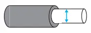 | 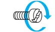 |  |
| S1, S2 | 4 mm 2 | ≤ 0.6 Nm | Pozidriv Z1 |
| Max. conductor diameter | 21 mm | ||
| Dimensions | 50 x 80 x 48 mm | ||
| Weight | 255 g. | ||
| Enclosure | UL94 Plástico V0 autoextinguible UL94 Self-extinguishing V0 plastic | ||
Standard
UNE-EN 61869-1, UNE-EN 61869-2
Dimensions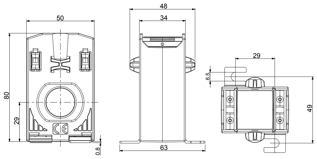
Connections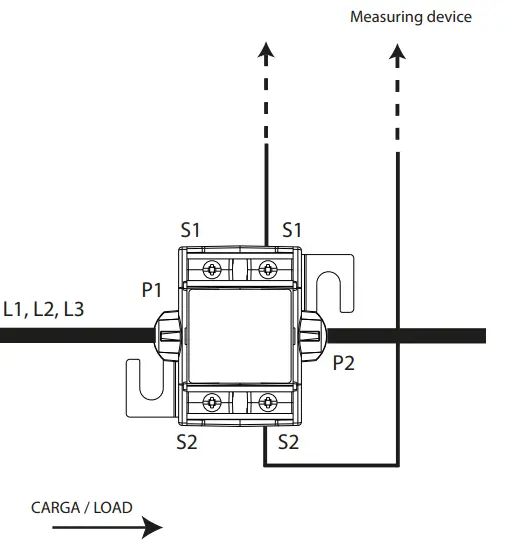
Terminal connections designations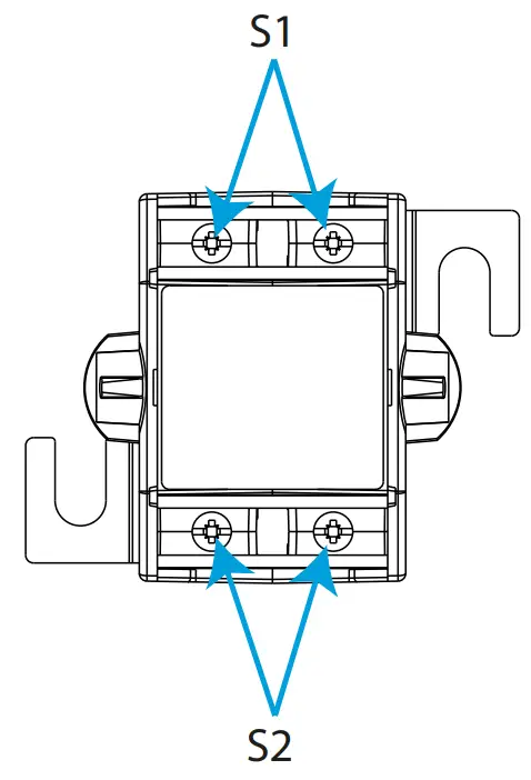
| S1 | Secondary of the transformer. |
| S2 | Secondary of the transformer. |
Rated current
| I (A) | CL 1 | CL 3 | I (A) | CL 0.5 | CL 1 | CL 3 |
| 40/5 | – | 1.25 VA | 100/5 | 1.50 VA | 2.50 VA | 5.00 VA |
| 50/5 | 1.00 VA | 1.50 VA | 125/5 | 2.50 VA | 3.75 VA | 5.00 VA |
| 60/5 | 1.25 VA | 2.50 VA | 150/5 | 3.75 VA | 5.00 VA | 5.00 VA |
| 75/5 | 1.50 VA | 3.75 VA | 200/5 | 5.00 VA | 7.50 VA | 7.50 VA |
Technical service
![]() CIRCUTOR SAT: 902 449 459 (SPAIN) / (+34) 937 452 919 (out of Spain)
CIRCUTOR SAT: 902 449 459 (SPAIN) / (+34) 937 452 919 (out of Spain)
Vial Sant Jordi, s/n
08232 – Viladecavalls (Barcelona)
Tel: (+34) 937 452 900 – Fax: (+34) 937 452 914
e-mail : [email protected]
M281A01-44-22A


