![]()
OLS20
Off-Line Power Supply/Charger
Installation Guide
Overview:
Altronix OLS20 power supply/charger converts 115VAC 50/60Hz input into a 12VDC @ 1A or 24VDC @ 0.5A of continuous supply current (refer to specifications). This general-purpose power supply has a wide range of applications for access control and security system accessories that require additional power.
Specifications:
Input:
- Input 115VAC 50/60Hz, 0.5A.
Output:
- 12VDC or 24VDC selectable operation.
- 0.5A continuous supply current @ 24VDC* 1A continuous supply current @ 12VDC*.
- Filtered and electronically regulated outputs.
- Short circuit and thermal overload protection.
Battery Backup:
- Built-in charger for sealed lead acid or gel type batteries.
* Specified at 25˚C ambient.
Battery Backup (cont’d):
- Maximum charge current 0.3A.
- Automatic switch over to stand-by battery when AC fails.
Additional Features:
- AC input and DC output LED indicators.
- Operating temperature: – 20ºC to 50ºC.
- Includes battery leads.
Board Dimensions (W x L x H approx.): 3” x 2.5” x 1” (76.2mm x 63.5mm x 25.4mm).
Voltage Output Selection Table:
| Output VDC | Switch Position | Max. Load DC |
| 12VDC | SW 1 – ON | 1.2A |
| 24VDC | SW1 – OFF | 0.5A |
Installation Instructions:
OLS20 should be installed in accordance with the National Electrical Code and all applicable Local Regulations.
- Mount the OLS20 in the desired location/enclosure (mounting hardware included).
- Set the OLS20 to the desired DC output voltage via SW1 (refer to Voltage Output Selection Table).
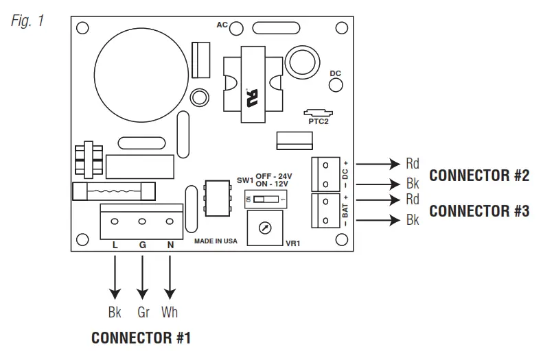
- Connect AC power to connector #1 (Fig. 1) (black & white flying leads) and ground (green flying lead) Use 18 AWG or larger for all power connections (Battery, AC input).
Keep power-limited wiring separate from non-power-limited wiring (115VAC 50/60Hz Input, Battery Wires). Minimum 0.25” spacing must be provided.
CAUTION: Do not touch exposed metal parts.
Shut branch circuit power before installing or servicing equipment.
There are no user-serviceable parts inside. Refer installation and servicing to qualified service personnel. - Measure output voltage before connecting devices. This helps avoiding potential damage.
- Connect devices to be powered to the terminals marked [– DC +] (Fig. 1).
- When the use of stand-by batteries is desired, they must be lead acid or gel type.
Connect battery to the terminals marked [– BAT +] (Fig. 1).
Use two (2) 12VDC batteries connected in series for 24VDC operation.
Note: When batteries are not used, a loss of AC will result in the loss of output voltage.
![]() For continuous protection against fire replace fuse with the same type and rating 5mm – 20mm, 250V, 2A.
For continuous protection against fire replace fuse with the same type and rating 5mm – 20mm, 250V, 2A.
LED Diagnostics:
| Red (DC) | Green (AC) | Power Supply Status |
| ON | ON | Normal operating condition. |
| ON | OFF | Loss of AC. The stand-by battery is supplying power. |
| OFF | ON | No DC output. Short circuit or thermal overload condition. |
| OFF | OFF | Loss of AC. Discharged or no stand-by battery. No DC output. |
Terminal Identification:
| Terminal Legend | Function/Description |
| L, G, N | Connect 115VAC to these terminals: Black to Hot, White to Neutral, Green to ground. |
| – DC + | 12VDC @ 1.0A continuous supply current. 24VDC @ 0.5A continuous supply current. |
| – BAT + | Stand-by battery connections. Maximum charge rate 0.3A. |
 Altronix is not responsible for any typographical errors.
140 58th Street, Brooklyn, New York 11220 USA
phone: 718-567-8181
fax: 718-567-9056
website: www.altronix.com
e-mail: [email protected]
Lifetime Warranty
IIOLS20 – Rev. 080905 H30U


