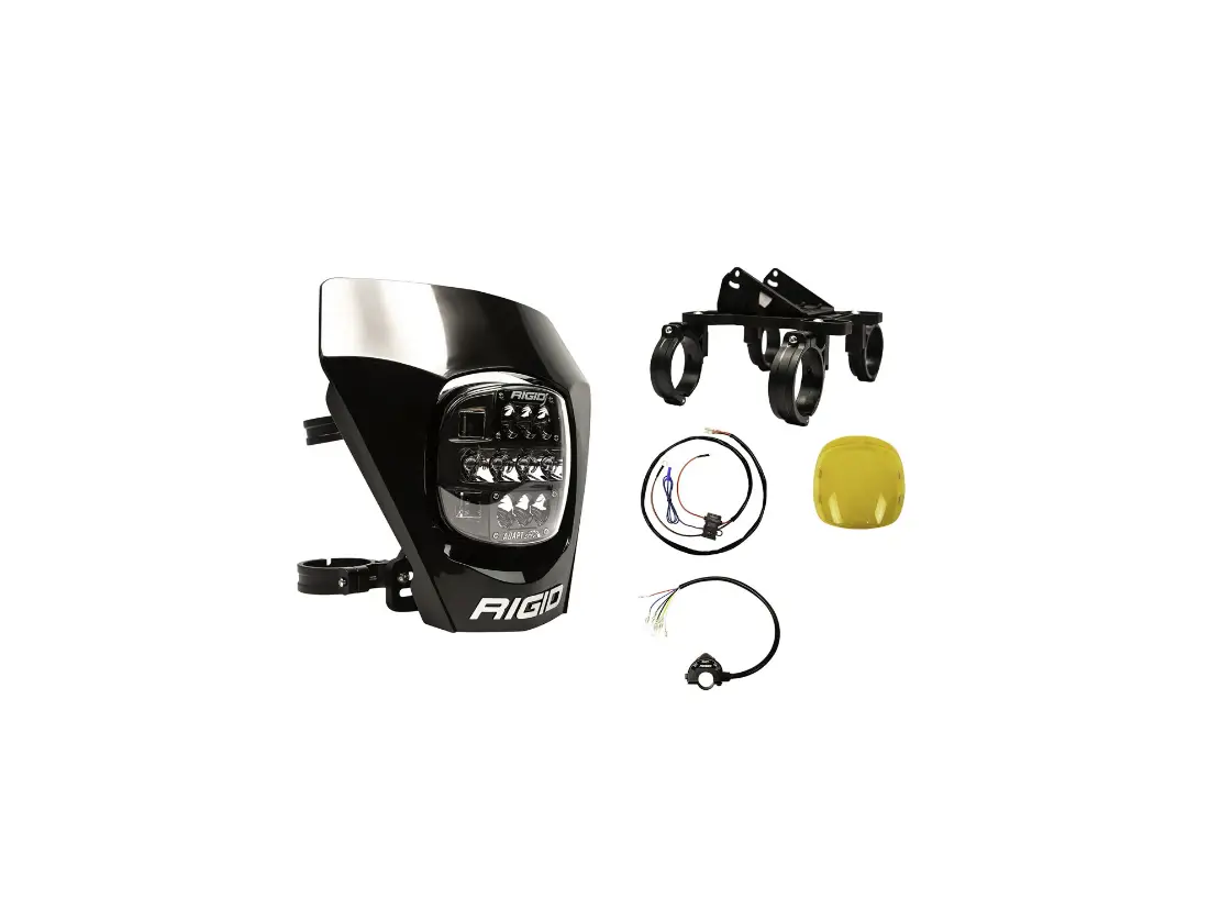
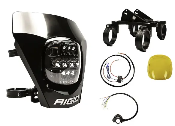
RIGID 300416 Adapt XE Extreme Enduro LED Moto Kit
IMPORTANT
THANK YOU FOR PURCHASING RIGID INDUSTRIES’ PRODUCTS FOR YOUR VEHICLE
Please read through all of these instructions and tips before proceeding with the installation. We do our best to provide a simple installation process for all applications, however a professional installation is always recommended.
Always disconnect any power sources connected to your vehicle before servicing fuses or electrical systems.
WIRING LEADS
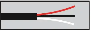
- RED WIRE = ON MODE VOLTAGE
- BLACK WIRE = GROUND
- WHITE WIRE = ADAPT MODE VOLTAGE
FUNCTIONALITY
Congrats on your purchase of the world’s first autonomous off-road light pod from RIGID! The Adapt-XE series has been engineered to operate with a 3-way switch. There are 3 modes: On, Off, & Adapt.
On Mode (red wire lead) will activate the entire light pod. The total available power from the vehicle will be distributed equally to all optic zones.
Adapt Mode (white wire lead) will activate the GPS mode for automatic functionality of the light pod based on the vehicle’s speed. Once powered on in Adapt Mode, the light pod requires 30-90 seconds to receive full satellite signal to the internal GPS module. During the time of signal acquisition, the light will be in On Mode.
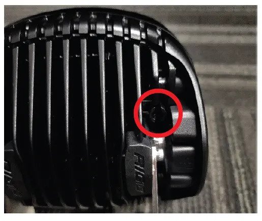
Magnetic Reed Power Clip (clip on rear of light housing) will allow the user to operate the light pod power output in two different modes. While the power clip is in the back of the pod, the power draw per light will be 40 Watts. When the clip is removed, the power of the Adapt XE light pod will increase to 80 Watts. The power clip is designed to snap into place on the back of the housing. It is recommended that a pair of needle nose pliers is used to squeeze the tabs together for easy removal. Should the clip need to be replaced, simply press it into the slot with your finger until you hear it audibly snap back into position.
ADAPT-XE ASSEMBLY DIAGRAM
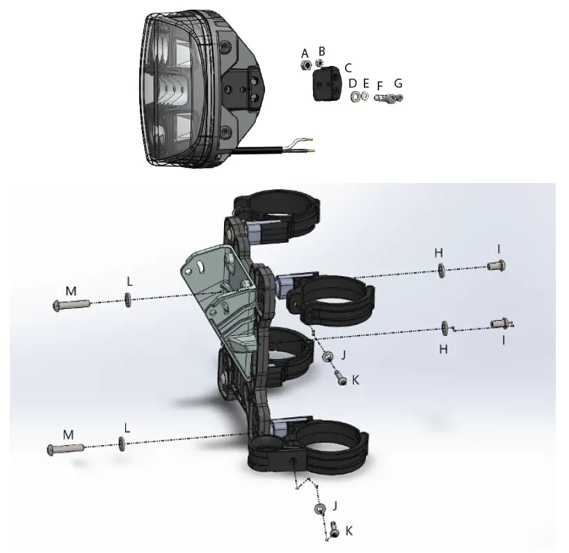
| A | M6 Ny Lock Nut | Place in heatsink |
| B | M4 Ny Lock Nut | Place into mount bushing |
| C | Mounting Bushing | Slide into heatsink |
| D | M6 Flat Washer | Place on J prior to install |
| E | M4 Flat Washer | Place on K prior to install |
| F | M6x22mm Socket Head | Tighten bracket to the light (Torque 32in-lbs) |
| G | M4x22mm Socket Head | Tighten bracket to the light (Torque 9in-lbs) |
| H | M6 Flat Washer (4) | Place on I prior to install |
| I | M6x12mm Button Socket Head (4) | Tighten bracket mount to bracket plate at desired height |
| J | M4 Flat Washer (4) | Place on K prior to install |
| K | M4x30mm Button Socket Head (4) | Tighten tube clamps to bike |
| L | M6 Flat Washer (4) | Place on M prior to install |
| M | M6x35mm Button Socket Head (4) | Tighten bracket plate to tube clamps |
ASSEMBLY INSTRUCTIONS
Bracket – Adapt XE
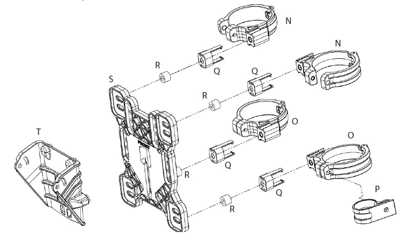
| N | Upper Tube Clamp (2) |
| O | Lower Tube Clamp (2) |
| P | Cable P-Clamp (2) |
| Q | Tube Clamp Spacer (4) |
| R | Unthreaded Spacer (4) |
| S | Bracket Plate |
| T | Bracket Mount |
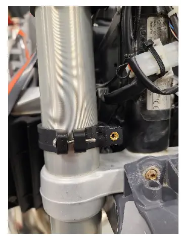
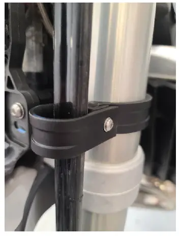
- Attach included tube clamp spacers (Q) to upper and lower tube clamps (N & O). Then place clamps onto front forks of the bike.
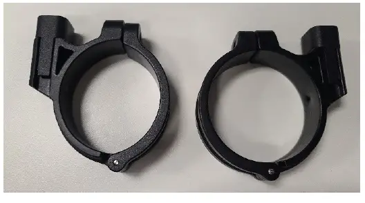
Note: The upper and lower tube clamps have a different shape. The upper clamp is smaller to account for the tapering of the fork tubes. See below: tube clamp on the left is the upper.

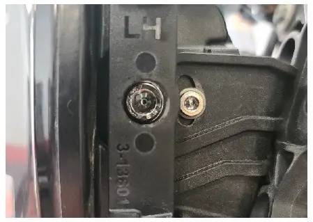
- Attach P-Clamp (P) to brake line for bottom tube clamp. Use second P-Clamp at upper tube clamp if applicable. Use M4 button socket head and M4 washer (J & K) to secure tube clamps to bike.

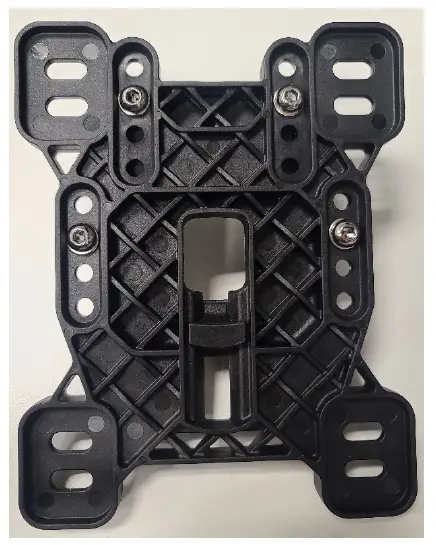
Note: Do not fully tighten M4 bolts to allow for adjustment later. - Slot the bracket mount (T) onto the bracket plate (S) and set to one of four optional heights. Use (4) M6 button socket head and flat washer (H & I) to secure bracket mount in desired position.

- Attach bracket plate (S) to tube clamps (N & O) using M6 button socket head bolts and M6 washers (L & M). Adjust each of the clamp heights to line up with one of two slotted holes in each corner of the mount plate.
Note: Once plate is bolted to the tube clamps, turn the handlebars as far as possible in either direction to ensure clearance of other electronics/parts installed between front forks. If tube clamps contact other parts, readjust clamp height/positioning until turning is not impeded. If additional spacing is needed between existing electronics/parts and the mount plate. Use the included unthreaded spacers (R) for additional space between the plate and the bike. Insert those on M6 bolts between the tube clamp spacers and the mounting plate.
- Once mount plate is installed in desired position and tube clamps to not make contact with other parts upon turning, tighten M4 button socket head bolts (K).
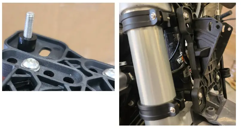
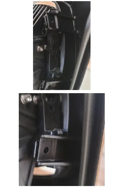
- Insert wiring on the back of the light through the hole in the center of the mounting plate/ bracket and use bushings, M6 bolts/washers/nylon lock nuts, and M4 bolts/washers/nylon lock nuts (A – G) to secure light to bracket.

- Snap number plate onto (4) clips on the light.

WIRING INSTRUCTIONS
3-Position Switch – Adapt XE
- Install provided 3-position switch on handlebar.
- Connect wiring as follows using bullet connectors:
- Yellow wire to red wire flying lead on light.
- Green wire to white wire flying lead on light.
- Red wire to red wire on wire harness.
- Blue wire to blue accessory wire on wire harness.
- Black ground wire on flying lead on light to black/red ground wire on provided wire harness.
- To make use of kill switch, wire as follows:
- Black wire to power (kill power)
- White wire to ground (kill ground)
- Connect positive and negative eyelets on harness to vehicle battery. (RED wire is positive, BLACK/ RED wire is negative.
NOTE: If bike does not have a battery installed, owner will need to splice power and ground into regulator wiring. It is recommended that power is drawn from a battery source to ensure constant power supply. - If applicable, connect accessory light or taillight to blue wire from harness to have it powered by the switch.
IMPORTANT
Always disconnect the vehicle battery terminals before servicing the electrical system - Locate suitable high and dry location to mount the relay close to vehicle battery in the engine compartment.
- When routing wire harness through vehicle firewall or any sheet metal panel ensure there are no sharp edges that could damage the harness. Protect the harness from damage by using a grommet or loom if needed.
- Route light, switch, and battery harness throughout the vehicle to their desired locations.
IMPORTANT
Once heat shrink butt connectors are crimped be sure to use a heat gun to seal the connector.
(Note: Never connect both RED and WHITE wires together) - Test functionality and adjust/aim the light pod.
WARRANTY INFORMATION
warranty information, visit ww.rigidindustries.com/about/warrantyw 779 N Colorado St, Gilbert, AZ 85233 • 855-760-5337 www.rigidindustries.com Adpat, Adapt XE and Rigid Industries are registered and/or common law marks owned by JST Performance, LLC, a Delaware limited liability company d/b/a Rigid Industries. 11-13904-A


